JP2005296832A - Solid phase automatic synthesizer - Google Patents
Solid phase automatic synthesizer Download PDFInfo
- Publication number
- JP2005296832A JP2005296832A JP2004117682A JP2004117682A JP2005296832A JP 2005296832 A JP2005296832 A JP 2005296832A JP 2004117682 A JP2004117682 A JP 2004117682A JP 2004117682 A JP2004117682 A JP 2004117682A JP 2005296832 A JP2005296832 A JP 2005296832A
- Authority
- JP
- Japan
- Prior art keywords
- reaction
- block
- reagent
- solvent
- solid phase
- Prior art date
- Legal status (The legal status is an assumption and is not a legal conclusion. Google has not performed a legal analysis and makes no representation as to the accuracy of the status listed.)
- Withdrawn
Links
Images


Landscapes
- Physical Or Chemical Processes And Apparatus (AREA)
Abstract
【課題】 固相合成を迅速に行い、固相を迅速に洗浄し、固相を迅速に乾燥することを同時に達成し、固相自動化装置において合成や洗浄に費やす時間を短縮すること。
【解決手段】 合成反応を行うための複数の反応試薬及び溶媒の保管容器、該反応試薬及び溶媒を微小管状反応管に供給するための配管、該反応試薬及び溶媒を微小管状反応器に供給させるための送液手段、微小管状反応器に所望の反応試薬及び溶媒だけを供給させるための切り替えバルブ、並びに反応基質固定化用担体が充填された微小管状反応器を含む固相自動合成装置であって、前記微小管状反応器内に必要量の反応試薬を送液後、送液を停止した状態で所望の合成反応を行わせ、反応終了後、担体に固定化された反応物以外の反応試薬を溶媒にて洗浄除去できる機能を有することを特徴とする固相自動合成装置。
【選択図】 なし
PROBLEM TO BE SOLVED: To simultaneously perform solid phase synthesis, quickly wash the solid phase, and dry the solid phase at the same time, and reduce the time spent for synthesis and washing in the solid phase automation apparatus.
A plurality of reaction reagent and solvent storage containers for carrying out a synthesis reaction, piping for supplying the reaction reagent and solvent to a microtubular reaction tube, and supplying the reaction reagent and solvent to the microtubular reactor A solid-phase automatic synthesizer including a liquid feeding means, a switching valve for supplying only a desired reaction reagent and a solvent to the microtubular reactor, and a microtubular reactor filled with a support for immobilizing a reaction substrate. Then, after the necessary amount of reaction reagent is fed into the microtubular reactor, the desired synthesis reaction is performed in a state where the liquid feed is stopped, and after the reaction is completed, the reaction reagent other than the reactant immobilized on the carrier A solid phase automatic synthesizer characterized by having a function capable of washing and removing with a solvent.
[Selection figure] None
Description
本発明は、目的化合物を自動的に合成する複数個の試薬や溶媒容器と複数個の反応容器から構成される自動合成装置及びそれを用いた固相自動合成方法に関する。特に、本発明は、固相合成において目的生成物を取得する際に、過剰の試薬や溶媒が発生する無駄を抑制し、合成や洗浄の際に撹拌混合を行う動力装置を備えずに、試薬の拡散混合時間や合成反応時間や固相の洗浄時間を著しく短縮した、固相自動合成装置及びそれを用いた固相自動合成方法に関する。 The present invention relates to an automatic synthesizer comprising a plurality of reagent and solvent containers for automatically synthesizing a target compound and a plurality of reaction containers, and a solid phase automatic synthesis method using the same. In particular, the present invention suppresses the waste of excessive reagents and solvents when obtaining a target product in solid-phase synthesis, and does not include a power device that performs stirring and mixing during synthesis and washing. The present invention relates to a solid phase automatic synthesizer and a solid phase automatic synthesis method using the same, in which the diffusion mixing time, synthesis reaction time, and solid phase washing time are significantly shortened.
製薬、バイオサイエンス又は化学などの研究分野において用いられている従来の自動合成装置は、合成反応をおこなう複数個の配列された反応容器を備えており、各反応器内に試薬や溶媒などをそれぞれ分注または送液するとともに、各反応器を冷却または加熱し、反応器内部を撹拌または反応器外部を振動することによって、各反応器内部の合成反応を促進させ、各反応器内部に生成化合物を生成するように構成されている。 Conventional automatic synthesizers used in research fields such as pharmaceuticals, biosciences, and chemistry are equipped with a plurality of arrayed reaction vessels that perform synthesis reactions, and each of the reactors contains reagents and solvents. In addition to dispensing or liquid feeding, each reactor is cooled or heated, the inside of the reactor is agitated or the outside of the reactor is vibrated to promote the synthesis reaction inside each reactor, and the product compound inside each reactor Is configured to generate
従来の固相合成装置において、生成化合物を取得するまでの一連の操作を、図3を参照して説明する。複数個の配列された合成反応をおこなう各反応容器の底部には加圧通液型フィルターと、各反応容器ごとに配備された回収容器がある。図3に示すように、先ずレジン粒子を反応容器に充填する。次に所定量の試薬を反応容器に添加する。反応容器の温度を、温度調節計にて所定の温度に調節し、反応器外部を回転振動させるかあるいは反応器内部に撹拌羽根または撹拌子を設置して、撹拌操作を所定時間実施する。次に反応器内を加圧して試薬を除去し、続いて洗浄溶媒を添加してレジンを洗浄する。洗浄は残存試薬が検出されなくなるまで複数回繰り返す。次に、切り出し液を添加し、所定時間放置したのち、レジンから生成化合物を下部から抜き出す。この際反応器内を加圧して、回収容器に生成化合物を取得する。切り出し液としては、生成化合物が何かによるが、切り出し液には、強酸性溶液か強塩基性溶液が用いられる。代表的な強塩基性溶液として、ナトリウムメトキシド/メタノール溶液などが、また代表的な強酸溶液としてフッ酸やトリフルオロメタンスルホン酸など知られている。 In a conventional solid-phase synthesizer, a series of operations until a product compound is obtained will be described with reference to FIG. At the bottom of each reaction vessel that performs a plurality of synthesis reactions arranged, there are a pressurized liquid-flowing filter and a collection vessel arranged for each reaction vessel. As shown in FIG. 3, first, resin particles are filled into a reaction vessel. Next, a predetermined amount of reagent is added to the reaction vessel. The temperature of the reaction vessel is adjusted to a predetermined temperature with a temperature controller, and the outside of the reactor is rotationally oscillated, or a stirring blade or a stirring bar is installed inside the reactor, and the stirring operation is performed for a predetermined time. Next, the inside of the reactor is pressurized to remove the reagent, and then the washing solvent is added to wash the resin. Washing is repeated several times until no remaining reagent is detected. Next, a cutting solution is added, and after leaving for a predetermined time, the product compound is extracted from the lower part of the resin. At this time, the inside of the reactor is pressurized, and the produced compound is obtained in the collection container. As the cutting solution, depending on what the product compound is, a strong acidic solution or a strongly basic solution is used as the cutting solution. As a typical strong basic solution, sodium methoxide / methanol solution and the like are known, and as a typical strong acid solution, hydrofluoric acid and trifluoromethanesulfonic acid are known.
また、このような、試薬の導入−反応−洗浄−分離及び精製−生成化合物の取得操作を自動化した自動合成装置としては固相合成と液相合成のものがあり、例えば、特許文献1及び2に記載のものが挙げられる。 In addition, such an automatic synthesizer that automates the reagent introduction-reaction-wash-separation and purification-product compound acquisition operation includes solid-phase synthesis and liquid-phase synthesis. For example, Patent Documents 1 and 2 The thing of description is mentioned.
しかしながら、特許文献1又は2に記されているような従来の固相自動合成装置は、図3に代表されるように、充填したレジン対し反応容器が大きく、またレジンを十分に浸漬させるために過剰量の試薬や溶媒を必要とし、そのため、よい混合を実現するために撹拌混合の動力手段を備えざるえない固相自動合成装置であった。さらに、複数個の反応容器と複数個の試薬や溶媒容器を備えた自動合成装置の場合、過剰の試薬や溶媒の量は著しいものとなり、無駄な廃液量が多く、環境負荷が高いという欠点があった。 However, the conventional solid-phase automatic synthesizer as described in Patent Document 1 or 2 has a large reaction vessel for the filled resin, as shown in FIG. It was a solid phase automatic synthesizer that required an excessive amount of reagent and solvent and therefore had to be equipped with a stirring and mixing power means in order to realize good mixing. Furthermore, in the case of an automatic synthesizer equipped with a plurality of reaction containers and a plurality of reagents and solvent containers, the amount of excess reagents and solvents becomes significant, resulting in a large amount of waste liquid and a high environmental load. there were.
本発明は上記した従来技術の問題点を解消することを解決すべき課題とした。即ち、本発明は、省資源・省エネルギーに関する観点から、過剰な試薬を使用せず、撹拌混合の動力手段の必要がない固相自動合成装置を提供することを解決すべき課題とした。 The present invention has been made to solve the above-described problems of the prior art. That is, the present invention has an object to be solved from the viewpoint of resource saving and energy saving to provide a solid phase automatic synthesizer that does not use excessive reagents and does not require a stirring and mixing power means.
また、固相合成を行う場合、反応は一定温度で行うことが多く、遅い反応を扱う場合、反応を昼夜ないし数日おこなうこともある。また、固相の洗浄においても、固相のレジンの粒子径とフィルター目開きの大きさの選び方によって、洗浄溶媒の迅速かつ円滑な送液の可能性、すなわち洗浄時間の短縮の可能性が決まる。また固相レジンの乾燥操作においても乾燥の雰囲気が乾燥時間の短縮の可能性を決める。本発明においては、固相合成を迅速に行い、固相を迅速に洗浄し、固相を迅速に乾燥することを同時に達成し、固相自動化装置において合成や洗浄に費やす時間を短縮することを解決すべき課題とした、即ち、本発明は、自動合成装置の全操作時間を短縮することを解決すべき課題とした。 In addition, when performing solid-phase synthesis, the reaction is often performed at a constant temperature, and when dealing with a slow reaction, the reaction may be performed day or night or several days. Also in solid phase washing, the possibility of rapid and smooth delivery of the washing solvent, that is, the possibility of shortening the washing time, is determined by the choice of the particle size of the solid phase resin and the size of the filter openings. . In the drying operation of the solid phase resin, the drying atmosphere determines the possibility of shortening the drying time. In the present invention, the solid phase synthesis can be performed quickly, the solid phase can be quickly washed and the solid phase can be quickly dried, and the time spent for synthesis and washing in the solid phase automation apparatus can be reduced. The problem to be solved, that is, the present invention was to solve the problem of shortening the total operation time of the automatic synthesis apparatus.
本発明者らは上記課題を解決するために鋭意検討した結果、省資源・省エネルギーに関する観点から、過剰な試薬を使用せず、撹拌混合の動力手段の必要がない固相自動合成装置を提供し、ついで、本固相自動合成装置において、内部の各部分の仕様や操作性を工夫することで、固相合成を素早く行い、固相を素早く洗浄し、固相を素早く乾燥し、合成や洗浄に費やす時間を短縮することに成功した。すなわち、本発明によれば以下の発明が提供される。 As a result of intensive investigations to solve the above problems, the present inventors have provided a solid phase automatic synthesizer that does not use excessive reagents and does not require a stirring and mixing power means from the viewpoint of resource saving and energy saving. Then, in this solid-phase automatic synthesizer, by devising the specifications and operability of each internal part, solid-phase synthesis is quickly performed, the solid phase is washed quickly, the solid phase is quickly dried, synthesis and washing We succeeded in shortening the time spent on. That is, according to the present invention, the following inventions are provided.
(1) 合成反応を行うための複数の反応試薬及び溶媒の保管容器、該反応試薬及び溶媒を微小管状反応管に供給するための配管、該反応試薬及び溶媒を微小管状反応器に供給させるための送液手段、微小管状反応器に所望の反応試薬及び溶媒だけを供給させるための切り替えバルブ、並びに反応基質固定化用担体が充填された微小管状反応器を含む固相自動合成装置であって、前記微小管状反応器内に必要量の反応試薬を送液後、送液を停止した状態で所望の合成反応を行わせ、反応終了後、担体に固定化された反応物以外の反応試薬を溶媒にて洗浄除去できる機能を有することを特徴とする固相自動合成装置。 (1) A plurality of reaction reagent and solvent storage containers for conducting a synthesis reaction, piping for supplying the reaction reagent and solvent to the microtubular reaction tube, and supplying the reaction reagent and solvent to the microtubular reactor A solid phase automatic synthesizer comprising: a liquid feeding means; a switching valve for supplying only a desired reaction reagent and solvent to the microtubular reactor; and a microtubular reactor filled with a support for immobilizing a reaction substrate. After the necessary amount of reaction reagent has been fed into the microtubular reactor, the desired synthesis reaction is carried out with the liquid feed stopped, and after the reaction is completed, a reaction reagent other than the reactant immobilized on the carrier A solid phase automatic synthesizer characterized by having a function capable of washing and removing with a solvent.
(2) 微小管状反応器の内径が0.1〜10cmであり、容量が0.5〜10mlである、(1)に記載の固相自動合成装置。
(3) 反応基質固定化用担体が樹脂である、(1)又は(2)に記載の固相自動合成装置。
(4) 反応試薬の必要量が反応管に充填された樹脂の膨潤相当量である、(3)に記載の固相自動合成装置。
(2) The solid phase automatic synthesizer according to (1), wherein the microtubular reactor has an inner diameter of 0.1 to 10 cm and a volume of 0.5 to 10 ml.
(3) The solid phase automatic synthesizer according to (1) or (2), wherein the reaction substrate immobilization carrier is a resin.
(4) The solid phase automatic synthesizer according to (3), wherein the required amount of the reaction reagent is an amount equivalent to the swelling of the resin filled in the reaction tube.
(5) 樹脂の膨潤が終了したことを液面センサーで検知して、送液を自動的に停止する機構を有する、(3)又は(4)に記載の固相自動合成装置。
(6) 樹脂の粒子径が、膨潤状態で2〜500ミクロンである、(3)から(5)の何れかに記載の固相自動合成装置。
(7) 多糖類合成用である、(1)から(6)の何れかに記載の固相自動合成装置。
(5) The solid phase automatic synthesizer according to (3) or (4), which has a mechanism for detecting the completion of resin swelling with a liquid level sensor and automatically stopping liquid feeding.
(6) The solid phase automatic synthesizer according to any one of (3) to (5), wherein the particle diameter of the resin is 2 to 500 microns in a swollen state.
(7) The solid phase automatic synthesizer according to any one of (1) to (6), which is used for polysaccharide synthesis.
(8) N個の配列された試薬及び溶媒容器群と、M個の配列された微小管状反応器群を含み、該試薬及び溶媒容器群と該微小管状反応器群との間に配置される切り替えバルブ群に関して、試薬及び溶媒容器群に接続されるM方切り替えバルブ群と微小管状反応器群に接続されるN方切り替えバルブ群(ここで、Mは2〜20の整数であり、Nは2〜20の整数である)を備えている、(1)から(7)の何れかに記載の固相自動合成装置。
(9) M個の微小管状反応器が直列に接続されている、(8)に記載の固相自動合成装置。
(10) 微小管状反応器の温度を調節するための温度調節部をさらに有し、該温度調節部が、初期温度と、終期温度と、初期温度と終期温度との間の昇温速度とを設定制御できる機能を有する、(1)から(9)の何れかに記載の固相自動合成装置。
(8) It includes N arrayed reagent and solvent container groups and M arrayed microtubular reactor groups, and is arranged between the reagent and solvent container groups and the microtubular reactor groups. Regarding the switching valve group, an M-way switching valve group connected to the reagent and solvent container group and an N-way switching valve group connected to the microtubular reactor group (where M is an integer from 2 to 20, The solid-phase automatic synthesizer according to any one of (1) to (7).
(9) The solid phase automatic synthesizer according to (8), wherein M microtubular reactors are connected in series.
(10) It further has a temperature control part for adjusting the temperature of the microtubular reactor, and the temperature control part has an initial temperature, an end temperature, and a rate of temperature increase between the initial temperature and the end temperature. The solid phase automatic synthesizer according to any one of (1) to (9), which has a function capable of setting control.
(11) 以下のAブロック〜Hブロックから構成される、(1)から(10)の何れかに記載の固相自動合成装置。
(A) ガス容器B1の不活性ガスを用いて送液操作を行う流量計MF1と乾燥操作を行う流量計MF2を備え、3方切り替えバルブV13により、乾燥操作か送液操作かが選択されるAブロック;
(B) 溶媒容器B2と溶媒容器B3からの極性溶媒及び無極性溶媒を用いて洗浄操作を行うためのポンプP1とポンプP2を備える、Bブロック;
(C) X個(Xは2〜17の整数を示す)の反応用の試薬ボトルB4からBY(ここで、YはX+3で表される整数を示す)の試薬を吸引して送液する操作を行うシリンジポンプS4からSYを備え、吸引か送液かを選択するためにX個の3方切り替えバルブV14からVZ(Z=X+13で表される整数を示す)を備える、Cブロック;
(D) Aブロックの不活性ガス、Bブロックの洗浄溶媒、CブロックのX個の試薬群を複数の反応容器に配分するための切り替えY個のバルブ群V1からVYを備える、Dブロック;
(E) Aブロックの不活性ガス、Bブロックの洗浄溶媒、CブロックのX個の試薬群をそれぞれ所定のM個(Mは2〜20の整数を示す)の反応容器に供給するためのM個の切り替えバルブと、反応器をバイパスして上流のバルブ群を乾燥したい場合に使用するM個の3方切り替えバルブを備える、ブロックE;
(F)固相であるレジン粒子を充填したM個の反応容器をブロックに固定保持した部分と温度センサーと液面センサーとを備える、ブロックF;
(G)M個の反応容器を通液した溶媒及び各種の試薬液を回収するトラップと切り出した生成液を回収するM個の回収ボトルを備える、ブロックG;及び
(H)AブロックからGブロックの流量制御、バルブ制御、温度制御及び液面制御を行うための手段を備える、Hブロック。
(11) The solid phase automatic synthesizer according to any one of (1) to (10), comprising the following A block to H block.
(A) A flow meter MF1 for performing a liquid feeding operation using an inert gas in the gas container B1 and a flow meter MF2 for performing a drying operation are provided, and a three-way switching valve V13 selects a drying operation or a liquid feeding operation. A block;
(B) B block comprising a pump P1 and a pump P2 for performing a washing operation using the polar solvent and the nonpolar solvent from the solvent container B2 and the solvent container B3;
(C) Operation for sucking and feeding BY (herein, Y represents an integer represented by X + 3) reagents from X reagent bottles B4 for reaction (X represents an integer of 2 to 17) A C block including syringe pumps S4 to SY for performing X, and X three-way switching valves V14 to VZ (indicating an integer represented by Z = X + 13) to select suction or liquid feeding;
(D) D block comprising switching Y valve groups V1 to VY for distributing the inert gas of block A, the cleaning solvent of block B, and the X reagent groups of block C to a plurality of reaction vessels;
(E) M for supplying an inert gas in the A block, a cleaning solvent in the B block, and X reagent groups in the C block to predetermined M (M represents an integer of 2 to 20) reaction vessels, respectively. Block E, comprising M switching valves and M three-way switching valves used when it is desired to dry the upstream valve group bypassing the reactor;
(F) a block F including a portion in which M reaction vessels filled with resin particles as a solid phase are fixedly held on the block, a temperature sensor, and a liquid level sensor;
(G) A block G including a trap for collecting the solvent and various reagent liquids passed through the M reaction vessels and M collection bottles for collecting the cut out product liquid; and (H) A block to G block. H block comprising means for performing flow rate control, valve control, temperature control and liquid level control.
(12) M個の反応容器を同時に溶媒洗浄でき、またM個の反応容器を同時に乾燥することができるように、AブロックとBブロックとEブロックにさらに追加の3方切り替えバルブが備えられている、(11)に記載の固相自動合成装置。 (12) An additional three-way switching valve is provided in the A block, the B block, and the E block so that the M reaction vessels can be simultaneously solvent-washed and the M reaction vessels can be dried simultaneously. The solid phase automatic synthesizer according to (11).
(13) (1)から(12)の何れかに記載の固相自動合成装置を用いて、固相自動合成を行う方法。
(14) 反応試薬及び溶媒の送液を、不活性ガスを用いて圧送することにより行う、(13)に記載の方法。
(15) 極性溶媒と無極性溶媒を併用して洗浄を行う、(13)又は(14)に記載の方法。
(13) A method for performing solid phase automatic synthesis using the solid phase automatic synthesizer according to any one of (1) to (12).
(14) The method according to (13), wherein the reaction reagent and the solvent are fed by pumping using an inert gas.
(15) The method according to (13) or (14), wherein washing is performed using a polar solvent and a nonpolar solvent in combination.
本発明の固相自動合成装置によれば、レジン膨潤量の反応試薬を用いることができるので、過剰な試薬の排出がなく、また撹拌など動力手段が不要である。また、効果的な極性及び無極性の洗浄溶媒を選ぶことによって、洗浄溶媒量を最小化でき、採択する反応の速度に依存するところはあるが、昇温反応により反応時間を短縮でき、適当な大きさレジンと相応のフィルターを選ぶことにより、洗浄時間が短縮され、窒素流通と真空乾燥を併用することにより乾燥時間が短縮化できる。即ち、本発明の固相自動合成装置によれば、省資源・省エネルギーを達成することが可能である。 According to the solid phase automatic synthesizer of the present invention, a reaction reagent having a resin swelling amount can be used, so that excessive reagent is not discharged and no power means such as stirring is required. In addition, by selecting an effective polar and non-polar washing solvent, the amount of washing solvent can be minimized, and depending on the reaction rate to be adopted, there are some cases where the temperature rise reaction can shorten the reaction time, and an appropriate amount. By choosing a size resin and a corresponding filter, the washing time can be shortened, and by using a combination of nitrogen flow and vacuum drying, the drying time can be shortened. That is, according to the solid phase automatic synthesizer of the present invention, it is possible to achieve resource saving and energy saving.
以下、本発明の実施の形態について詳細に説明する。
本発明の固相自動合成装置では、ストップドフロー反応をマイクロスケールで行うことにより、過剰の試薬を使用することなく効率よく反応を行わせることが可能である。また、自動固相合成の反応工程は煩雑であるが、自動化システムを構成しているので操作が簡単であり自動化が容易である。また、マイクロスケールで行った場合でも、必要とされる量の多糖類、ペプチドを合成するためには十分な規模である。
Hereinafter, embodiments of the present invention will be described in detail.
In the solid-phase automatic synthesizer of the present invention, the stopped flow reaction can be performed on a microscale, so that the reaction can be efficiently performed without using an excessive reagent. In addition, the reaction process of the automatic solid phase synthesis is complicated, but since the automation system is configured, the operation is simple and the automation is easy. Moreover, even when performed on a microscale, the scale is sufficient to synthesize the required amount of polysaccharides and peptides.
例えば、多糖類の合成例として、以下のようなものが挙げられる。
(1)微小管状反応器内に、アミノ基を有する樹脂を充填しておく
(2)反応器に、チオフェニル基を有する単糖カルボン酸と結合試薬とを導入する。
(3)ストップドフロー反応により、ペプチド結合で単糖を樹脂に結合させる。
(4)反応液を溶媒で洗浄除去する。
(5)反応器内に、フッ化単糖誘導体と結合試薬を導入する。
(6)ストップドフロー反応により、樹に担持された糖とフッ化単糖誘導体とを反応させて、両者をエーテル結合で結合させる。
(7)反応液を溶媒で洗浄除去する。
(8)上記(5)〜(8)の反応を繰り返し、糖鎖を成長させていく。
For example, the following is mentioned as an example of a polysaccharide synthesis.
(1) A microtubular reactor is filled with a resin having an amino group. (2) A monosaccharide carboxylic acid having a thiophenyl group and a binding reagent are introduced into the reactor.
(3) A monosaccharide is bound to the resin by a peptide bond by a stopped flow reaction.
(4) The reaction solution is washed away with a solvent.
(5) A fluorinated monosaccharide derivative and a binding reagent are introduced into the reactor.
(6) By a stopped-flow reaction, the sugar supported on the tree is reacted with the fluorinated monosaccharide derivative, and both are bonded by an ether bond.
(7) The reaction solution is washed away with a solvent.
(8) Repeat the reactions (5) to (8) above to grow sugar chains.
また、かかる装置はペプチド合成にも応用される。この場合も、アミノ基を有する樹脂、必要に応じ側鎖官能基が保護されているアミノ酸のカルボキシル基と樹脂との間にペプチド結合を形成させる反応を行う。更に、樹脂に担持されたアミノ酸のアミノ基と、次のアミノ酸のカルボキシル基を反応させてペプチド結合を形成させる。かかる反応を繰り返し、糖鎖を成長させていくことができる。 Such an apparatus is also applied to peptide synthesis. Also in this case, a reaction for forming a peptide bond between a resin having an amino group and, if necessary, a carboxyl group of an amino acid whose side chain functional group is protected and the resin is performed. Further, the amino group of the amino acid supported on the resin is reacted with the carboxyl group of the next amino acid to form a peptide bond. Such reactions can be repeated to grow sugar chains.
本発明で用いる反応基質固定化用担体としては、一般的には、通常、溶媒使用時にいくらか膨潤する性質を有する樹脂製のものを使用することが好ましい。但し、樹脂でも架橋度が高いもの、あるいは、シリカなどの無機担体の表面にアミノ基を化学結合させたものや、該無機担体に樹脂をコーテイングしたものなどでもよく、これらについては、溶媒に接しても殆ど膨潤しない性質のものがある。かかる反応基質固定化用担体の場合における必要反応試薬量は、担体の細孔部も含む表面を溶媒の膜で覆われる程度の量を意味する。 In general, the carrier for immobilizing a reaction substrate used in the present invention is preferably a resin-made carrier having a property of swelling somewhat when a solvent is used. However, it may be a resin having a high degree of cross-linking, or a resin in which an amino group is chemically bonded to the surface of an inorganic carrier such as silica, or a resin coated on the inorganic carrier. However, there is a property that hardly swells. The amount of the necessary reaction reagent in the case of such a reaction substrate immobilization carrier means an amount that covers the surface including the pores of the carrier with a solvent film.
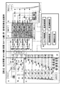
続いて、本発明の装置の構成を図面を参照しながら説明する。図1に実施例に関わる固相自動合成装置の全体構成を示すブロック図を示す。本実施例において、試薬及び溶媒容器群に接続されるM方切り替えバルブ群と反応容器群に接続されるN方切り替えバルブ群において、Mが4個、Nが12個であるが、反応容器の個数Mと試薬容器の個数Nが、特にMが4個そしてNが12個に限定されるものではない。 Next, the configuration of the apparatus of the present invention will be described with reference to the drawings. FIG. 1 is a block diagram showing the overall configuration of the solid phase automatic synthesizer according to the embodiment. In this example, in the M-way switching valve group connected to the reagent and solvent container group and the N-way switching valve group connected to the reaction container group, M is 4 and N is 12. The number M and the number N of reagent containers are not particularly limited to 4 for M and 12 for N.
必要に応じて、多方切り替えバルブの組み合わせを増やし、反応管系列の増設と拡張が可能であり、多品種の生成物を迅速に作成する操作(ハイスループットスクリーニング)に有利である自動合成装置である。 It is an automatic synthesizer that is advantageous for operations (high-throughput screening) that can quickly create a wide variety of products by increasing the number of combinations of multi-way switching valves as required, allowing expansion and expansion of reaction tube series. .
(Aブロック)
ガス容器B1の不活性ガスを用いて送液操作を行う流量計MF1と乾燥操作を行う流量計MF2を備える。送液操作を行う流量計の流量は1SCCM(standard cc/min)から10SCCMと低流量が好ましい。乾燥操作を行う流量計の流量は前記の流量計より大きい流量がよく、500SCCMから2000SCCMが好ましい。3方切り替えバルブV13により、乾燥操作か送液操作かを選択する。
(Block A)
A flow meter MF1 that performs a liquid feeding operation using an inert gas in the gas container B1 and a flow meter MF2 that performs a drying operation are provided. The flow rate of the flowmeter for performing the liquid feeding operation is preferably a low flow rate of 1 SCCM (standard cc / min) to 10 SCCM. The flow rate of the flow meter for performing the drying operation should be larger than the above flow meter, and is preferably 500 SCCM to 2000 SCCM. With the three-way switching valve V13, a drying operation or a liquid feeding operation is selected.
(Bブロック)
溶媒容器B2と溶媒容器B3から極性溶媒及び無極性溶媒を用いて洗浄操作を行うポンプP1とポンプP2を備える。ポンプの流量は1mL毎分から10mL毎分が好ましい。
極性溶媒は分極率の高い溶媒であればよく、レジン中の残存試薬を効率よく洗浄する働きがある。極性溶媒として、N、N’−ジメチルホルムアミド、プロピオニトリル、アセトニトリル、メタノール、エタノール、プロパノール、N−メチルピロリドン、THFなどが使用できる。無極性溶媒は分極率の低い溶媒であればよく、極性溶媒を置換洗浄した後の乾燥操作において、蒸発しやすい性質のものを選べば、乾燥時間が短縮できる。無極性溶媒として、ジクロルエタン、ジクロルメタンなどのハロゲン化炭化水素、ヘキサン、ヘプタンなどの脂肪族炭化水素、及びベンゼンやトルエンなどの芳香族炭化水素が好ましい。
また、レジンに水分を残存させないために、極性溶媒及び無極性溶媒のとも、脱水溶媒と呼ばれる水分が極端に除去された溶媒を使うことが好ましい。
(B block)
A pump P1 and a pump P2 that perform a cleaning operation using a polar solvent and a nonpolar solvent from the solvent container B2 and the solvent container B3 are provided. The flow rate of the pump is preferably 1 mL / min to 10 mL / min.
The polar solvent may be a solvent having a high polarizability, and has a function of efficiently washing the remaining reagent in the resin. As the polar solvent, N, N′-dimethylformamide, propionitrile, acetonitrile, methanol, ethanol, propanol, N-methylpyrrolidone, THF and the like can be used. The nonpolar solvent may be a solvent having a low polarizability, and the drying time can be shortened by selecting a solvent that easily evaporates in the drying operation after substitution washing of the polar solvent. As the nonpolar solvent, halogenated hydrocarbons such as dichloroethane and dichloromethane, aliphatic hydrocarbons such as hexane and heptane, and aromatic hydrocarbons such as benzene and toluene are preferable.
Further, in order not to leave moisture in the resin, it is preferable to use a solvent from which water is extremely removed, called a dehydrated solvent, for both polar and nonpolar solvents.
(Cブロック)
複数の反応用の試薬ボトルB4からB12の試薬を吸引し送液する操作を行うシリンジポンプS4からS12を備える。吸引か送液かを選択するために3方切り替えバルブV14からV22を備える。シリンジポンプに使用するシリンジの大きさは合成の規模に依存するが通常1mLから10mLで十分である。
(C block)
Syringe pumps S4 to S12 that perform an operation of sucking and feeding the reagents in B12 from a plurality of reagent bottles B4 for reaction are provided. Three-way switching valves V14 to V22 are provided to select suction or liquid feeding. The size of the syringe used for the syringe pump depends on the scale of synthesis, but 1 to 10 mL is usually sufficient.
(Dブロック)
Aブロックの不活性ガス、Bブロックの洗浄溶媒、Cブロックの複数の試薬群を複数の反応容器に配分するための切り替えバルブ群V1からV12を備える。バルブは市販のものが使用でき、バルブの材質は耐食性かつ耐有機溶剤性のものがよく、特にテフロン(登録商標)製またはテフロン(登録商標)でコートしたSUS製が好ましい。バルブの耐圧性は0.1MPaから1MPaあれば十分である。またコンタミをさけるため、好ましくは死容積の小さいバルブがよい。
(D block)
There are provided switching valve groups V1 to V12 for distributing the inert gas of the A block, the cleaning solvent of the B block, and the plurality of reagent groups of the C block to the plurality of reaction vessels. A commercially available valve can be used, and the material of the valve is preferably a corrosion-resistant and organic solvent-resistant material. In particular, Teflon (registered trademark) or SUS coated with Teflon (registered trademark) is preferable. A pressure resistance of the valve of 0.1 MPa to 1 MPa is sufficient. In order to avoid contamination, a valve with a small dead volume is preferable.
(Eブロック)
Aブロックの不活性ガス、Bブロックの洗浄溶媒、Cブロックの複数の試薬群をそれぞれ所定の反応容器に供給するための切り替えバルブ群VA、VB、VC、VDを備える。反応器をバイパスして上流のバルブ群の乾燥したい場合使用する3方切り替えバルブV23からV26を備える。バルブの材質と耐圧性は前記同様である。
(E block)
There are provided switching valve groups VA, VB, VC, VD for supplying an inert gas of block A, a cleaning solvent of block B, and a plurality of reagent groups of block C to predetermined reaction vessels, respectively. Three-way switching valves V23 to V26 are used for bypassing the reactor and drying the upstream valve group. The material and pressure resistance of the valve are the same as described above.
(Fブロック)
固相であるレジン粒子を充填した反応容器R1からR4をアルミ製ブロックに固定保持した部分と温度センサーと液面センサーを備える。
固相であるレジンの具体例としては、各種の樹脂、例えば、ポリスチレン樹脂、ポリアクリルアミド樹脂、ポリエーテル系樹脂、及びそれらの複合樹脂や、または多孔質ガラス、多孔質ビーズ、キャピラリーシリカやマイクロチップなどの微細流路、セファロースなどが挙げられる。これらはいずれも、固相合成に際してリンカーやスペーサーなどを連結するための足場となる、アミノ基、ブロモメチル基、水酸基、チオール基、カルボキシル基などの官能基を有しているものであって、さらに適当な側鎖や修飾などを有するものであってよい。
(F block)
A reaction vessel R1 to R4 filled with resin particles as a solid phase is fixed to an aluminum block, and a temperature sensor and a liquid level sensor are provided.
Specific examples of the solid phase resin include various resins such as polystyrene resin, polyacrylamide resin, polyether resin, and composite resins thereof, or porous glass, porous beads, capillary silica, and microchips. And fine flow paths such as sepharose. These all have a functional group such as an amino group, a bromomethyl group, a hydroxyl group, a thiol group, or a carboxyl group that serves as a scaffold for linking a linker or spacer during solid phase synthesis, It may have an appropriate side chain or modification.
(Gブロック)
反応管R1からR4に通液した、溶媒及び各種の試薬液を回収するトラップと切り出した生成液を回収する回収ボトルT1からT4を備える。また不活性ガスを流しながら、真空排気による乾燥操作をおこなう真空ラインを備える。
(G block)
A trap for collecting the solvent and various reagent liquids passed through the reaction tubes R1 to R4 and collection bottles T1 to T4 for collecting the cut out product liquid are provided. In addition, a vacuum line is provided for performing a drying operation by evacuation while flowing an inert gas.
(Hブロック)
あらかじめプログラム設定されたAブロックの流量制御、Bブロックの流量制御と圧力の監視、Cブロックの流量制御と切り替えバルブ操作、Dブロックの切り替えバルブ操作、Eブロックの切り替えバルブ操作、Fブロックの温度制御と温度の監視と液面制御、Gブロックのバルブ開閉操作と真空動力のオンオフの操作を、シーケンサーを経由しておこなう、タッチパネル型制御計またはパーソナルコンピューターを備える。
(H block)
Pre-programmed A block flow control, B block flow control and pressure monitoring, C block flow control and switching valve operation, D block switching valve operation, E block switching valve operation, F block temperature control A touch panel type controller or personal computer that performs temperature monitoring, liquid level control, G block valve opening / closing operation, and vacuum power on / off operation via a sequencer.
続いて、本発明の固相自動合成装置の反応工程と洗浄工程と乾燥工程の特徴について記述する。
(本発明の固相自動合成装置の反応工程における特徴)
試薬や溶媒の拡散混合時間を節約するためには、反応容器は小型であることがよく、反応管1系列の内径が100〜120000ミクロン、好ましくは1000〜100000ミクロンで、その長さが0.3mmから300000mmでかつその容量が10mL以下であり、好ましくは1mL以下であり、より好ましくは0.5mLである。同体積であれば、好ましくは円盤状よりは円筒状の管である反応管を採用する。
Subsequently, characteristics of the reaction process, the washing process, and the drying process of the solid phase automatic synthesizer of the present invention will be described.
(Characteristics in the reaction process of the solid phase automatic synthesizer of the present invention)
In order to save the diffusion mixing time of the reagent and the solvent, the reaction vessel should be small, the inner diameter of one series of reaction tubes is 100 to 120,000 microns, preferably 1000 to 100000 microns, and the length is 0.1. The volume is 3 to 300,000 mm and the volume is 10 mL or less, preferably 1 mL or less, more preferably 0.5 mL. If it is the same volume, the reaction tube which is preferably a cylindrical tube rather than a disk shape is employed.
また、反応試薬の使用量を必要最小量の「反応管に保持されたレジンの膨潤相当量」とし、過剰の試薬の量を用いることなく、環境負荷が少ない方法である。さらにこの方式は別の利点をもつ。すなわち、レジンは多孔質体であり、反応管に保持されたレジン内部の微小流路内で反応を実施するため、本質的に拡散混合時間tが短い。 In addition, the amount of the reaction reagent used is the minimum necessary amount “equivalent to swelling of the resin held in the reaction tube”, and the method has a low environmental burden without using an excessive amount of reagent. Furthermore, this scheme has other advantages. That is, the resin is a porous body, and the reaction is carried out in the micro flow path inside the resin held in the reaction tube, so that the diffusion mixing time t is essentially short.
t=r2÷D (式1)
t:拡散混合時間 r:多孔質体の細孔半径 D:拡散係数
t = r 2 ÷ D (Formula 1)
t: Diffusion mixing time r: Pore radius of porous body D: Diffusion coefficient
例えば、細孔半径が10ミクロンの多孔質体内でのショ糖の拡散は、D=0.5×10⁻⁹m2/secであり、(式1)によれば、拡散混合時間は1秒以内である。試薬の撹拌のために振動や回転などの動力をまったく用いる必要はないといえる。 For example, the diffusion of sucrose in a porous body having a pore radius of 10 microns is D = 0.5 × 10 −9 m 2 / sec, and according to (Equation 1), the diffusion mixing time is 1 second. Is within. It can be said that it is not necessary to use power such as vibration and rotation for stirring the reagent.
本発明では、必要最小量であるレジン膨潤量の反応試薬を反応管内に保持されたレジンまで輸送するのに、窒素などの不活性ガスを用いて圧送し、レジンに液が到達し膨潤が終了したことを液面センサーで検出し、送液を停止することができる。すなわち、液面センサーを反応管の出口に設置してレジンに試薬が浸みだしてきた時点で液面を検出し、送液を停止し、不必要に試薬が供給されることを確実に防止することができる。 In the present invention, the minimum amount of resin swelled reaction reagent is transported to the resin held in the reaction tube by pumping with an inert gas such as nitrogen, and the liquid reaches the resin and the swelling ends. This can be detected by the liquid level sensor, and the liquid feeding can be stopped. In other words, a liquid level sensor is installed at the outlet of the reaction tube to detect the liquid level when the reagent begins to soak in the resin, stop liquid feeding, and reliably prevent unnecessary reagent supply be able to.
反応部のプログラム温度制御に関して、取り扱う反応の活性化エネルギーEaと生成物の熱分解性を考慮して、遅い反応であれば、適切な初期温度と終期温度と保持時間と昇温速度を設定し、昇温反応を実施して、反応時間を短縮することが可能である。
k(T+△T)/k(T)=exp(−Ea/R(1/(T+△T)−1/T)(式2)
k:1次速度定数 T:温度 △T:温度差 Ea:活性化エネルギー
Regarding the programmed temperature control of the reaction part, considering the activation energy Ea of the reaction to be handled and the thermal decomposability of the product, if the reaction is slow, set appropriate initial temperature, final temperature, holding time, and heating rate. It is possible to shorten the reaction time by performing a temperature rising reaction.
k (T + ΔT) / k (T) = exp (−Ea / R (1 / (T + ΔT) −1 / T) (Formula 2)
k: First-order rate constant T: Temperature ΔT: Temperature difference Ea: Activation energy
例えば、活性化エネルギーEa=50Kcal/molの1次反応であれば、反応温度を30℃あげることにより反応速度が約2倍となり、よって反応時間を約1/2に短縮できる。 For example, in the case of a primary reaction with activation energy Ea = 50 Kcal / mol, the reaction rate is about doubled by raising the reaction temperature by 30 ° C., and thus the reaction time can be reduced to about ½.
(本発明の固相自動合成装置の洗浄工程における特徴)
レジン内に残存する試薬化合物の洗浄効果の向上させるために、N,N’−ジメチルホルムアミドなどの極性溶媒とジクロルエタンなどの無極性溶媒を併用する。通常レジン内に残存しやすい化合物は水などの極性を有する化合物である。これらを除去するには、極性溶媒がよい。本法においては、レジン約100mgに対し、レジン内部に浸透した試薬を最初に約2Lの窒素で送り追いだし、次にラインを洗浄するためにジクロルエタン等の無極性溶媒を約5mLで洗い、次にレジン中の極性化合物を除去するためにN,N’−ジメチルホルムアミド等の極性溶媒で約10mLで洗い、最後にジクロルエタン等の無極性溶媒を約5mLで洗う。最後に無極性溶媒で洗うのは極性溶媒が一般に沸点が高く、乾燥工程での蒸発除去に時間がかかるため、乾燥時間の節約のため必要である。合計の洗浄時間は約20分である。
(Characteristics in the washing process of the solid phase automatic synthesizer of the present invention)
In order to improve the cleaning effect of the reagent compound remaining in the resin, a polar solvent such as N, N′-dimethylformamide and a nonpolar solvent such as dichloroethane are used in combination. Usually, the compound that tends to remain in the resin is a compound having polarity such as water. To remove these, a polar solvent is preferred. In this method, for about 100 mg of the resin, the reagent that has penetrated into the resin is first sent out with about 2 L of nitrogen, and then a nonpolar solvent such as dichloroethane is washed with about 5 mL to wash the line. In order to remove the polar compound in the resin, it is washed with about 10 mL of a polar solvent such as N, N′-dimethylformamide, and finally with about 5 mL of a nonpolar solvent such as dichloroethane. Finally, washing with a non-polar solvent is necessary for saving the drying time because the polar solvent generally has a high boiling point and takes time to evaporate and remove in the drying process. The total cleaning time is about 20 minutes.
また、洗浄工程においてはレジン粒子の大きさとレジンを保持するために設けられているフィルター目開きの大きさにより、閉塞や圧上昇の問題があり、迅速かつ円滑な洗浄のためには、適当な大きさを採用する必要がある。 Also, in the cleaning process, there are problems of clogging and pressure increase due to the size of the resin particles and the size of the filter openings provided to hold the resin. It is necessary to adopt the size.
本法においては、固相として使用するレジンの粒子径が溶媒を吸収した状態で2〜500ミクロン、特に30〜400ミクロンであることが好ましい。また、レジンを反応容器内に保持する際に、使用するフィルター目開きが30ミクロン以上、好ましくが100ミクロン以上でレジンを流出しない大きさであるものを採用することが好ましい。市販のフィルターは、例えばLC用のものは5ミクロンから20ミクロンであり、送液にかなり圧がかかる。本法のものを使用すれば圧は0.5MPa程度である。 In this method, it is preferable that the particle diameter of the resin used as the solid phase is 2 to 500 microns, particularly 30 to 400 microns in a state where the solvent is absorbed. In addition, when the resin is held in the reaction vessel, it is preferable to employ a resin having a filter opening size of 30 microns or more, preferably 100 microns or more and a size that does not flow out of the resin. Commercially available filters, for example, for LC are 5 to 20 microns, and the liquid feeding is considerably pressured. If the method is used, the pressure is about 0.5 MPa.
(本発明の固相自動合成装置の乾燥工程における特徴)
レジン中の溶媒を除去するために、Aブロックより約2Lの窒素を流通するが、真空ポンプを用いて反応管内を減圧にし、乾燥を迅速におこなうことができる。乾燥時間は約30分である。
(Characteristics in the drying process of the solid phase automatic synthesizer of the present invention)
In order to remove the solvent in the resin, about 2 L of nitrogen is circulated from the A block, but the inside of the reaction tube can be depressurized using a vacuum pump, and drying can be performed quickly. The drying time is about 30 minutes.
さらなる洗浄時間と乾燥時間の短縮の方法として、図2では、AブロックとBブロックとEブロックに追加の3方切り替えバルブV35〜V44を備えた自動合成装置を提案する。この方式では、反応容器R1〜R4を同時に溶媒洗浄操作可能であり、また同時に乾燥操作可能であるので、著しく操作時間の短縮が可能である。
以下の実施例により本発明をさらに具体的に説明するが、本発明は実施例によって限定されるものではない。
As a method for further shortening the washing time and drying time, FIG. 2 proposes an automatic synthesizer provided with additional three-way switching valves V35 to V44 in the A block, B block and E block. In this method, the reaction vessels R1 to R4 can be subjected to solvent washing operation simultaneously and can be dried simultaneously, so that the operation time can be remarkably shortened.
The following examples further illustrate the present invention, but the present invention is not limited to the examples.
上記した図1又は図2に記載の本発明の固相自動合成装置を用いて糖を合成する実施例を以下に示す。 Examples of synthesizing sugar using the solid phase automatic synthesizer of the present invention described in FIG. 1 or FIG. 2 will be shown below.
1.糖鎖合成における固相自動合成装置の自動操作法
参考文献J.Am.Chem.Soc.116、12073−12074(1994)に記載される反応の方法により、ベンジル基を保護基とする保護単糖、フェニル−1−チオ−2,3−ジベンジル−4−O−サクシニル−L−フコピラノシド(試薬Aと略す)、3,4,6−トリ−O−ベンジル−D−ガラクトピラノシルフルオライド(試薬Bと略す)、フェニル−1−チオ−2,3,6−トリ−O−ベンジル−D−グルコピラノシド(試薬Cと略す)を用いて、グルコース−ガラクトース−フコースの3糖誘導体を自動合成する。
1. Automatic operation method of solid phase automatic synthesizer in sugar chain synthesis Am. Chem. Soc. 116, 12073-12074 (1994), a protected monosaccharide having a benzyl group as a protecting group, phenyl-1-thio-2,3-dibenzyl-4-O-succinyl-L-fucopyranoside ( (Abbreviated as reagent A), 3,4,6-tri-O-benzyl-D-galactopyranosyl fluoride (abbreviated as reagent B), phenyl-1-thio-2,3,6-tri-O-benzyl A trisaccharide derivative of glucose-galactose-fucose is automatically synthesized using -D-glucopyranoside (abbreviated as reagent C).
2.レジンのセットアップ
Novabiochem社のNovasynTGアミノレジン(アミノ基濃度0.29mmol/g)15mgを反応管R1に充填する。
2. Resin Setup Novabiochem NovasynTG aminoresin (amino group concentration 0.29 mmol / g) 15 mg is charged into the reaction tube R1.
3.試薬のセットアップ
ボトルB2に脱水ジクロルエタンを200ml、ボトルB3に脱水N,N‘−ジメチルホルムアミド(DMFと略す)を200ml入れる。
シリンジS4に、試薬Aを5mg、N,N‘−ジイソプロピルカルボジイミド2μl及び1−ヒドロキシベンゾトリアゾール2mgを脱水DMF0.2mlに溶解して充填する。
シリンジS5に、試薬Bを3mg、ジメチルジスルフィド3μl及びメチルトリフラート3μlを脱水ジクロルエタン0.05mlと脱水アセトニトリル0,05mlに溶解させ、モレキュラーシーブ4Aを2mg添加し、ろ過したたものを充填する。
シリンジS6に、試薬Cを3mg及びトリフル酸銀5mgを脱水ジクロルエタン0.06mlと脱水アセトニトリル0.06mlに溶解させ、モレキュラーシーブ4Aを4mg添加し、ろ過したものを充填する。
シリンジS7に、1−オクタノール8μl、ジメチルスルフィド3μl及びメチルトリフラート3μlを脱水ジクロルエタン0.06mlと脱水アセトニトリルに溶解させ、モレキュラーシーブ4Aを2mg添加し、ろ過したものを充填する。
シリンジS8に、ピリジン0.5mlと無水酢酸0.5mlを混合したものを充填する。
シリンジS9に、0.25Mナトリウムメトキシド・メタノール溶液を1ml充填する。
3. Reagent Setup Place 200 ml of dehydrated dichloroethane in bottle B2 and 200 ml of dehydrated N, N′-dimethylformamide (abbreviated as DMF) in bottle B3.
In syringe S4, 5 mg of reagent A, 2 μl of N, N′-diisopropylcarbodiimide and 2 mg of 1-hydroxybenzotriazole are dissolved in 0.2 ml of dehydrated DMF and filled.
In Syringe S5, 3 mg of Reagent B, 3 μl of dimethyl disulfide and 3 μl of methyl triflate are dissolved in 0.05 ml of dehydrated dichloroethane and 0.055 ml of dehydrated acetonitrile, and 2 mg of molecular sieve 4A is added and filtered.
In Syringe S6, 3 mg of Reagent C and 5 mg of silver triflate are dissolved in 0.06 ml of dehydrated dichloroethane and 0.06 ml of dehydrated acetonitrile, and 4 mg of molecular sieve 4A is added, followed by filtration.
In syringe S7, 8 μl of 1-octanol, 3 μl of dimethyl sulfide and 3 μl of methyl triflate are dissolved in 0.06 ml of dehydrated dichloroethane and dehydrated acetonitrile, and 2 mg of molecular sieve 4A is added and filtered.
Syringe S8 is filled with a mixture of 0.5 ml of pyridine and 0.5 ml of acetic anhydride.
Syringe S9 is filled with 1 ml of a 0.25M sodium methoxide / methanol solution.
4.レジンの乾燥
質量流量計MF2から窒素を反応管R1に流せるようにバルブV13、バルブV1、バルブVA、バルブV23、バルブV27を切り替え、反応管R1を真空ラインで脱気できるように、バルブV31を切り替え、反応管R1に窒素を30分間流し、アミノレジンを洗浄及び乾燥する。
4). Drying of resin Valve V13, valve V1, valve VA, valve V23, and valve V27 are switched so that nitrogen can flow from the mass flow meter MF2 to the reaction tube R1, and the valve V31 is set so that the reaction tube R1 can be degassed by a vacuum line. After switching, nitrogen is passed through the reaction tube R1 for 30 minutes to wash and dry the aminoresin.
5.1糖目のレジンへの結合
反応管R1の温度を20℃にする。反応管R1にシリンジS4から試薬を流せるように、バルブV14,バルブV4、バルブVA、バルブV23、バルブV27、バルブV31を切り替え、シリンジS4より、送液流量100μ/minで0.12ml量を送液し、所定量に達したら、シリンジポンプを停止する。次に質量流量計MF1から窒素を反応管R1に流せるように、バルブV13、バルブV1、バルブVAを切り替え、窒素を1SCCM以下で流し、反応試薬を反応管R1へ導く。レジンの膨潤が終了し、反応試薬が反応管R1の出口に達し、出口に設置された液面センサーで反応試薬の存在を検知したら、バルブV13、バルブV23、バルブV27を閉とし、反応管内に反応試薬を保ったまま、12時間静置し、反応を行う。
5. Binding to the first sugar resin The temperature of the reaction tube R1 is set to 20 ° C. The valve V14, the valve V4, the valve VA, the valve V23, the valve V27, and the valve V31 are switched so that the reagent can flow from the syringe S4 to the reaction tube R1, and a 0.12 ml amount is sent from the syringe S4 at a liquid feed flow rate of 100 μ / min. When the liquid reaches a predetermined amount, the syringe pump is stopped. Next, the valve V13, the valve V1, and the valve VA are switched so that nitrogen can flow from the mass flow meter MF1 to the reaction tube R1, nitrogen is flowed at 1 SCCM or less, and the reaction reagent is guided to the reaction tube R1. When the swelling of the resin is completed, the reaction reagent reaches the outlet of the reaction tube R1, and the presence of the reaction reagent is detected by a liquid level sensor installed at the outlet, the valves V13, V23, and V27 are closed, and the reaction tube is placed in the reaction tube. While keeping the reaction reagent, the reaction is allowed to stand for 12 hours.
6.洗浄と乾燥
質量流量計MF2から窒素を反応管R1からトラップボトルに流せるように、バルブV13、バルブV1、バルブVA、バルブV23、バルブV27、バルブV31を切り替え、窒素を100ml/minの流量で流し、反応液をトラップボトルに回収する。次に、ボトルB2からジクロルエタンを反応管R1経由でトラップボトルに流せるように、ポンプP2を起動し、バルブV2、バルブVAを切り替えて、ジクロルエタン流量1ml/minで反応管内のレジンを5分間洗浄し、ポンプP2を停止する。次に、ボトルB3からDMFを流せるように、ポンプP3を起動し、バルブV3、バルブVAを切り替えて、DMF流量1ml/minで反応管内のレジンを10分間洗浄し、ポンプP3を停止する。次に、ボトルB2からジクロルエタンを反応管R1経由でトラップボトルに流せるように、ポンプP2を起動し、バルブV2、バルブVAを切り替えて、ジクロルエタン流量1ml/minで反応管内のレジンを10分間洗浄し、ポンプP2を停止する。
6). Cleaning and drying Valve V13, valve V1, valve VA, valve V23, valve V27, and valve V31 are switched so that nitrogen can flow from the mass flow meter MF2 to the trap bottle from the reaction tube R1, and nitrogen is flowed at a flow rate of 100 ml / min. Collect the reaction solution in a trap bottle. Next, the pump P2 is started so that dichloroethane can flow from the bottle B2 to the trap bottle via the reaction tube R1, the valves V2 and VA are switched, and the resin in the reaction tube is washed for 5 minutes at a dichloroethane flow rate of 1 ml / min. Then, the pump P2 is stopped. Next, the pump P3 is activated so that DMF can flow from the bottle B3, the valves V3 and VA are switched, the resin in the reaction tube is washed for 10 minutes at a DMF flow rate of 1 ml / min, and the pump P3 is stopped. Next, the pump P2 is started so that dichloroethane can flow from the bottle B2 to the trap bottle via the reaction tube R1, the valves V2 and VA are switched, and the resin in the reaction tube is washed at a dichloroethane flow rate of 1 ml / min for 10 minutes. Then, the pump P2 is stopped.
7.残アミノ基のキャッピング
反応管R1の温度を20℃にする。反応管R1にシリンジS8から試薬を流せるように、バルブV18,バルブV8、バルブVA、バルブV23、バルブV27、バルブV31を切り替え、シリンジS8より、送液流量100μ/minで送液し、試薬を反応管R1へ導き、試薬が反応管R1の出口に達し、出口に設置された液面センサーで試薬の存在を検知したら、バルブV13、バルブV23、バルブV27を閉とし、反応管内に反応試薬を保ったまま、12時間静置し、レジン中のアミノ基を無水酢酸でキャッピングする反応を行う。
7). Capping of residual amino group The temperature of the reaction tube R1 is set to 20 ° C. The valve V18, valve V8, valve VA, valve V23, valve V27, and valve V31 are switched so that the reagent can flow from the syringe S8 to the reaction tube R1, and the reagent is sent from the syringe S8 at a liquid feeding flow rate of 100 μ / min. When the reagent reaches the outlet of the reaction tube R1, the reagent reaches the outlet of the reaction tube R1, and the presence of the reagent is detected by the liquid level sensor installed at the outlet, the valve V13, the valve V23, and the valve V27 are closed, and the reaction reagent is placed in the reaction tube. The mixture is left to stand for 12 hours, and the amino group in the resin is capped with acetic anhydride.
8.洗浄と乾燥
質量流量計MF2から窒素を反応管R1からトラップボトルに流せるように、バルブV13、バルブV1、バルブVA、バルブV23、バルブV27、バルブV31を切り替え、窒素を100ml/minの流量で流し、反応液をトラップボトルに回収する。次に、ボトルB2からジクロルエタンを反応管R1経由でトラップボトルに流せるように、ポンプP2を起動し、バルブV2、バルブVAを切り替えて、ジクロルエタン流量1ml/minで反応管内のレジンを5分間洗浄し、ポンプP2を停止する。次に、ボトルB3からDMFを流せるように、ポンプP3を起動し、バルブV3、バルブVAを切り替えて、DMF流量1ml/minで反応管内のレジンを10分間洗浄し、ポンプP3を停止する。次に、ボトルB2からジクロルエタンを反応管R1経由でトラップボトルに流せるように、ポンプP2を起動し、バルブV2、バルブVAを切り替えて、ジクロルエタン流量1ml/minで反応管内のレジンを10分間洗浄し、ポンプP2を停止する。
8). Cleaning and drying Valve V13, valve V1, valve VA, valve V23, valve V27, and valve V31 are switched so that nitrogen can flow from the mass flow meter MF2 to the trap bottle from the reaction tube R1, and nitrogen is flowed at a flow rate of 100 ml / min. Collect the reaction solution in a trap bottle. Next, the pump P2 is started so that dichloroethane can flow from the bottle B2 to the trap bottle via the reaction tube R1, the valves V2 and VA are switched, and the resin in the reaction tube is washed for 5 minutes at a dichloroethane flow rate of 1 ml / min. Then, the pump P2 is stopped. Next, the pump P3 is activated so that DMF can flow from the bottle B3, the valves V3 and VA are switched, the resin in the reaction tube is washed for 10 minutes at a DMF flow rate of 1 ml / min, and the pump P3 is stopped. Next, the pump P2 is started so that dichloroethane can flow from the bottle B2 to the trap bottle via the reaction tube R1, the valves V2 and VA are switched, and the resin in the reaction tube is washed at a dichloroethane flow rate of 1 ml / min for 10 minutes. Then, the pump P2 is stopped.
9.2糖目の結合
反応管R1の温度を0℃にする。反応管R1にシリンジS5から試薬を流せるように、バルブV15,バルブV5、バルブVA、バルブV23、バルブV27、バルブV31を切り替え、シリンジS5より、送液流量100μ/minで0.10ml量を送液し、所定量に達したら、シリンジポンプを停止する。次に質量流量計MF1から窒素を反応管R1に流せるように、バルブV13、バルブV1、バルブVAを切り替え、窒素を1SCCM以下で流し、反応試薬を反応管R1へ導く。レジンの膨潤が終了し、反応試薬が反応管R1の出口に達し、出口に設置された液面センサーで反応試薬の存在を検知したら、バルブV13、バルブV23、バルブV27を閉とし、反応管内に反応試薬を保ったまま、12時間静置し、反応を行う。
9.2 Bonding of the 2nd sugar The temperature of the reaction tube R1 is set to 0 ° C. The valve V15, the valve V5, the valve VA, the valve V23, the valve V27, and the valve V31 are switched so that the reagent can flow from the syringe S5 to the reaction tube R1, and a 0.10 ml amount is sent from the syringe S5 at a liquid feed flow rate of 100 μ / min. When the liquid reaches a predetermined amount, the syringe pump is stopped. Next, the valve V13, the valve V1, and the valve VA are switched so that nitrogen can flow from the mass flow meter MF1 to the reaction tube R1, nitrogen is flowed at 1 SCCM or less, and the reaction reagent is guided to the reaction tube R1. When the swelling of the resin is completed, the reaction reagent reaches the outlet of the reaction tube R1, and the presence of the reaction reagent is detected by a liquid level sensor installed at the outlet, the valves V13, V23, and V27 are closed, and the reaction tube is placed in the reaction tube. While keeping the reaction reagent, the reaction is allowed to stand for 12 hours.
10.洗浄と乾燥
質量流量計MF2から窒素を反応管R1からトラップボトルに流せるように、バルブV13、バルブV1、バルブVA、バルブV23、バルブV27、バルブV31を切り替え、窒素を100ml/minの流量で流し、反応液をトラップボトルに回収する。次に、ボトルB2からジクロルエタンを反応管R1経由でトラップボトルに流せるように、ポンプP2を起動し、バルブV2、バルブVAを切り替えて、ジクロルエタン流量1ml/minで反応管内のレジンを5分間洗浄し、ポンプP2を停止する。次に、ボトルB3からDMFを流せるように、ポンプP3を起動し、バルブV3、バルブVAを切り替えて、DMF流量1ml/minで反応管内のレジンを10分間洗浄し、ポンプP3を停止する。次に、ボトルB2からジクロルエタンを反応管R1経由でトラップボトルに流せるように、ポンプP2を起動し、バルブV2、バルブVAを切り替えて、ジクロルエタン流量1ml/minで反応管内のレジンを10分間洗浄し、ポンプP2を停止する。
10. Cleaning and drying Valve V13, valve V1, valve VA, valve V23, valve V27, and valve V31 are switched so that nitrogen can flow from the mass flow meter MF2 to the trap bottle from the reaction tube R1, and nitrogen is flowed at a flow rate of 100 ml / min. Collect the reaction solution in a trap bottle. Next, the pump P2 is started so that dichloroethane can flow from the bottle B2 to the trap bottle via the reaction tube R1, the valves V2 and VA are switched, and the resin in the reaction tube is washed for 5 minutes at a dichloroethane flow rate of 1 ml / min. Then, the pump P2 is stopped. Next, the pump P3 is activated so that DMF can flow from the bottle B3, the valves V3 and VA are switched, the resin in the reaction tube is washed for 10 minutes at a DMF flow rate of 1 ml / min, and the pump P3 is stopped. Next, the pump P2 is started so that dichloroethane can flow from the bottle B2 to the trap bottle via the reaction tube R1, the valves V2 and VA are switched, and the resin in the reaction tube is washed at a dichloroethane flow rate of 1 ml / min for 10 minutes. Then, the pump P2 is stopped.
11.3糖目の結合
反応管R1の温度を−15℃にする。反応管R1にシリンジS6から試薬を流せるように、バルブV16,バルブV6、バルブVA、バルブV23、バルブV27、バルブV31を切り替え、シリンジS6より、送液流量100μ/minで0.12ml量を送液し、所定量に達したら、シリンジポンプを停止する。次に質量流量計MF1から窒素を反応管R1に流せるように、バルブV13、バルブV1、バルブVAを切り替え、窒素を1SCCM以下で流し、反応試薬を反応管R1へ導く。レジンの膨潤が終了し、反応試薬が反応管R1の出口に達し、出口に設置された液面センサーで反応試薬の存在を検知したら、バルブV13、バルブV23、バルブV27を閉とし、反応管内に反応試薬を保ったまま、反応温度を−15℃から20℃に昇温速度1℃/hで温度を上げながら、その間12時間静置し、反応を行う。
11.3 Bonding of sugar The temperature of the reaction tube R1 is set to -15 ° C. The valve V16, valve V6, valve VA, valve V23, valve V27, and valve V31 are switched so that the reagent can flow from the syringe S6 to the reaction tube R1, and a 0.12 ml amount is sent from the syringe S6 at a liquid feed flow rate of 100 μ / min. When the liquid reaches a predetermined amount, the syringe pump is stopped. Next, the valve V13, the valve V1, and the valve VA are switched so that nitrogen can flow from the mass flow meter MF1 to the reaction tube R1, nitrogen is flowed at 1 SCCM or less, and the reaction reagent is guided to the reaction tube R1. When the swelling of the resin is completed, the reaction reagent reaches the outlet of the reaction tube R1, and the presence of the reaction reagent is detected by a liquid level sensor installed at the outlet, the valves V13, V23, and V27 are closed, and the reaction tube is placed in the reaction tube. While maintaining the reaction reagent, the reaction temperature is increased from -15 ° C to 20 ° C at a heating rate of 1 ° C / h, and the reaction is carried out by allowing to stand for 12 hours.
12.洗浄と乾燥
質量流量計MF2から窒素を反応管R1からトラップボトルに流せるように、バルブV13、バルブV1、バルブVA、バルブV23、バルブV27、バルブV31を切り替え、窒素を100ml/minの流量で流し、反応液をトラップボトルに回収する。次に、ボトルB2からジクロルエタンを反応管R1経由でトラップボトルに流せるように、ポンプP2を起動し、バルブV2、バルブVAを切り替えて、ジクロルエタン流量1ml/minで反応管内のレジンを5分間洗浄し、ポンプP2を停止する。次に、ボトルB3からDMFを流せるように、ポンプP3を起動し、バルブV3、バルブVAを切り替えて、DMF流量1ml/minで反応管内のレジンを10分間洗浄し、ポンプP3を停止する。次に、ボトルB2からジクロルエタンを反応管R1経由でトラップボトルに流せるように、ポンプP2を起動し、バルブV2、バルブVAを切り替えて、ジクロルエタン流量1ml/minで反応管内のレジンを5分間洗浄し、ポンプP2を停止する。
12 Cleaning and drying Valve V13, valve V1, valve VA, valve V23, valve V27, and valve V31 are switched so that nitrogen can flow from the mass flow meter MF2 to the trap bottle from the reaction tube R1, and nitrogen is flowed at a flow rate of 100 ml / min. Collect the reaction solution in a trap bottle. Next, the pump P2 is started so that dichloroethane can flow from the bottle B2 to the trap bottle via the reaction tube R1, the valves V2 and VA are switched, and the resin in the reaction tube is washed for 5 minutes at a dichloroethane flow rate of 1 ml / min. Then, the pump P2 is stopped. Next, the pump P3 is activated so that DMF can flow from the bottle B3, the valves V3 and VA are switched, the resin in the reaction tube is washed for 10 minutes at a DMF flow rate of 1 ml / min, and the pump P3 is stopped. Next, the pump P2 is started so that dichloroethane can flow from the bottle B2 to the trap bottle via the reaction tube R1, the valves V2 and VA are switched, and the resin in the reaction tube is washed for 5 minutes at a dichloroethane flow rate of 1 ml / min. Then, the pump P2 is stopped.
13.1−オクタノールによるエステル誘導体化
反応管R1の温度を20℃にする。反応管R1にシリンジS7から試薬を流せるように、バルブV17,バルブV7、バルブVA、バルブV23、バルブV27、バルブV31を切り替え、シリンジS7より、送液流量100μ/minで送液し、試薬を反応管R1へ導き、試薬が反応管R1の出口に達し、出口に設置された液面センサーで試薬の存在を検知したら、バルブV13、バルブV23、バルブV27を閉とし、反応管内に反応試薬を保ったまま、12時間静置し、レジン中の3糖誘導体の1−オクタノール化反応を行う。
13. Ester derivatization with 1-octanol The temperature of the reaction tube R1 is brought to 20 ° C. The valve V17, valve V7, valve VA, valve V23, valve V27, and valve V31 are switched so that the reagent can flow from the syringe S7 to the reaction tube R1, and the reagent is sent from the syringe S7 at a flow rate of 100 μ / min. When the reagent reaches the outlet of the reaction tube R1, the reagent reaches the outlet of the reaction tube R1, and the presence of the reagent is detected by the liquid level sensor installed at the outlet, the valve V13, the valve V23, and the valve V27 are closed, and the reaction reagent is placed in the reaction tube. While keeping it for 12 hours, the 1-octanolation reaction of the trisaccharide derivative in the resin is performed.
14.洗浄と乾燥
質量流量計MF2から窒素を反応管R1からトラップボトルに流せるように、バルブV13、バルブV1、バルブVA、バルブV23、バルブV27、バルブV31を切り替え、窒素を100ml/minの流量で流し、反応液をトラップボトルに回収する。次に、ボトルB2からジクロルエタンを反応管R1経由でトラップボトルに流せるように、ポンプP2を起動し、バルブV2、バルブVAを切り替えて、ジクロルエタン流量1ml/minで反応管内のレジンを5分間洗浄し、ポンプP2を停止する。次に、ボトルB3からDMFを流せるように、ポンプP3を起動し、バルブV3、バルブVAを切り替えて、DMF流量1ml/minで反応管内のレジンを10分間洗浄し、ポンプP3を停止する。次に、ボトルB2からジクロルエタンを反応管R1経由でトラップボトルに流せるように、ポンプP2を起動し、バルブV2、バルブVAを切り替えて、ジクロルエタン流量1ml/minで反応管内のレジンを10分間洗浄し、ポンプP2を停止する。
14 Cleaning and drying Valve V13, valve V1, valve VA, valve V23, valve V27, and valve V31 are switched so that nitrogen can flow from the mass flow meter MF2 to the trap bottle from the reaction tube R1, and nitrogen is flowed at a flow rate of 100 ml / min. Collect the reaction solution in a trap bottle. Next, the pump P2 is started so that dichloroethane can flow from the bottle B2 to the trap bottle via the reaction tube R1, the valves V2 and VA are switched, and the resin in the reaction tube is washed for 5 minutes at a dichloroethane flow rate of 1 ml / min. Then, the pump P2 is stopped. Next, the pump P3 is activated so that DMF can flow from the bottle B3, the valves V3 and VA are switched, the resin in the reaction tube is washed for 10 minutes at a DMF flow rate of 1 ml / min, and the pump P3 is stopped. Next, the pump P2 is started so that dichloroethane can flow from the bottle B2 to the trap bottle via the reaction tube R1, the valves V2 and VA are switched, and the resin in the reaction tube is washed at a dichloroethane flow rate of 1 ml / min for 10 minutes. Then, the pump P2 is stopped.
15.切り出し
反応管R1の温度を20℃にする。反応管R1にシリンジS9から試薬を流せるように、バルブV19,バルブV9、バルブVA、バルブV23、バルブV27、バルブV31を切り替え、シリンジS9より、送液流量100μl/minで送液し、試薬を反応管R1へ導き、試薬が反応管R1の出口に達し、出口に設置された液面センサーで試薬の存在を検知したら、バルブV13、バルブV23、バルブV27を閉とし、反応管内に反応試薬を保ったまま、2時間静置し、レジン中の3糖誘導体の切り出し反応を行う。
15. Cutting The temperature of the reaction tube R1 is set to 20 ° C. The valve V19, valve V9, valve VA, valve V23, valve V27, and valve V31 are switched so that the reagent can flow from the syringe S9 to the reaction tube R1, and the reagent is sent from the syringe S9 at a liquid feeding flow rate of 100 μl / min. When the reagent reaches the outlet of the reaction tube R1, the reagent reaches the outlet of the reaction tube R1, and the presence of the reagent is detected by the liquid level sensor installed at the outlet, the valve V13, the valve V23, and the valve V27 are closed, and the reaction reagent is placed in the reaction tube. While keeping it for 2 hours, the trisaccharide derivative in the resin is excised.
16.生成物の回収
反応管R1の温度を20℃にする。反応管R1に質量流量計MF2から窒素を流し、上記切り出し液をボトルT4に回収できるように、バルブV13,バルブV1、バルブVA、バルブV23、バルブV27、バルブV31を切り替え、質量流量計MF2より、流量100ml/minで窒素を流し、切り出し液をT4へ導き、回収する。
16. Product Recovery The temperature of the reaction tube R1 is brought to 20 ° C. Nitrogen is allowed to flow from the mass flow meter MF2 to the reaction tube R1, and the valve V13, valve V1, valve VA, valve V23, valve V27, and valve V31 are switched so that the cutting liquid can be collected in the bottle T4, from the mass flow meter MF2. Then, nitrogen is allowed to flow at a flow rate of 100 ml / min, and the cutting liquid is guided to T4 and collected.
17.操作終了後の反応管の洗浄と乾燥
質量流量計MF2から窒素を反応管R1からトラップボトルに流せるように、バルブV13、バルブV1、バルブVA、バルブV23、バルブV27、バルブV31を切り替え、窒素を100ml/minの流量で流し、反応液をトラップボトルに回収する。次に、ボトルB2からジクロルエタンを反応管R1経由でトラップボトルに流せるように、ポンプP2を起動し、バルブV2、バルブVAを切り替えて、ジクロルエタン流量1ml/minで反応管内のレジンを5分間洗浄し、ポンプP2を停止する。次に、ボトルB3からDMFを流せるように、ポンプP3を起動し、バルブV3、バルブVAを切り替えて、DMF流量1ml/minで反応管内のレジンを10分間洗浄し、ポンプP3を停止する。次に、ボトルB2からジクロルエタンを反応管R1経由でトラップボトルに流せるように、ポンプP2を起動し、バルブV2、バルブVAを切り替えて、ジクロルエタン流量1ml/minで反応管内のレジンを10分間洗浄し、ポンプP2を停止する。
17. Cleaning and drying of the reaction tube after the operation is completed. Switch the valve V13, the valve V1, the valve VA, the valve V23, the valve V27, and the valve V31 so that nitrogen can flow from the mass flow meter MF2 to the trap bottle. Flow at a flow rate of 100 ml / min and collect the reaction solution in a trap bottle. Next, the pump P2 is started so that dichloroethane can flow from the bottle B2 to the trap bottle via the reaction tube R1, the valves V2 and VA are switched, and the resin in the reaction tube is washed for 5 minutes at a dichloroethane flow rate of 1 ml / min. Then, the pump P2 is stopped. Next, the pump P3 is activated so that DMF can flow from the bottle B3, the valves V3 and VA are switched, the resin in the reaction tube is washed for 10 minutes at a DMF flow rate of 1 ml / min, and the pump P3 is stopped. Next, the pump P2 is started so that dichloroethane can flow from the bottle B2 to the trap bottle via the reaction tube R1, the valves V2 and VA are switched, and the resin in the reaction tube is washed at a dichloroethane flow rate of 1 ml / min for 10 minutes. Then, the pump P2 is stopped.
以上は、糖鎖の合成例であり、用いる試薬の流量および窒素の流量及び反応温度および反応時間等が、特に制約されるものではない。 The above is an example of sugar chain synthesis, and the flow rate of the reagent used, the flow rate of nitrogen, the reaction temperature, the reaction time, and the like are not particularly limited.
Claims (15)
(A) ガス容器B1の不活性ガスを用いて送液操作を行う流量計MF1と乾燥操作を行う流量計MF2を備え、3方切り替えバルブV13により、乾燥操作か送液操作かが選択されるAブロック;
(B) 溶媒容器B2と溶媒容器B3からの極性溶媒及び無極性溶媒を用いて洗浄操作を行うためのポンプP1とポンプP2を備える、Bブロック;
(C) X個(Xは2〜17の整数を示す)の反応用の試薬ボトルB4からBY(ここで、YはX+3で表される整数を示す)の試薬を吸引して送液する操作を行うシリンジポンプS4からSYを備え、吸引か送液かを選択するためにX個の3方切り替えバルブV14からVZ(Z=X+13で表される整数を示す)を備える、Cブロック;
(D) Aブロックの不活性ガス、Bブロックの洗浄溶媒、CブロックのX個の試薬群を複数の反応容器に配分するための切り替えY個のバルブ群V1からVYを備える、Dブロック;
(E) Aブロックの不活性ガス、Bブロックの洗浄溶媒、CブロックのX個の試薬群をそれぞれ所定のM個(Mは2〜20の整数を示す)の反応容器に供給するためのM個の切り替えバルブと、反応器をバイパスして上流のバルブ群を乾燥したい場合に使用するM個の3方切り替えバルブを備える、ブロックE;
(F)固相であるレジン粒子を充填したM個の反応容器をブロックに固定保持した部分と温度センサーと液面センサーとを備える、ブロックF;
(G)M個の反応容器を通液した溶媒及び各種の試薬液を回収するトラップと切り出した生成液を回収するM個の回収ボトルを備える、ブロックG;及び
(H)AブロックからGブロックの流量制御、バルブ制御、温度制御及び液面制御を行うための手段を備える、Hブロック。 The solid phase automatic synthesizer according to any one of claims 1 to 10, comprising the following A block to H block.
(A) A flow meter MF1 for performing a liquid feeding operation using an inert gas in the gas container B1 and a flow meter MF2 for performing a drying operation are provided, and a three-way switching valve V13 selects a drying operation or a liquid feeding operation. A block;
(B) B block comprising a pump P1 and a pump P2 for performing a washing operation using the polar solvent and the nonpolar solvent from the solvent container B2 and the solvent container B3;
(C) Operation for sucking and feeding BY (herein, Y represents an integer represented by X + 3) reagents from X reagent bottles B4 for reaction (X represents an integer of 2 to 17) A C block including syringe pumps S4 to SY for performing X, and X three-way switching valves V14 to VZ (indicating an integer represented by Z = X + 13) to select suction or liquid feeding;
(D) D block comprising switching Y valve groups V1 to VY for distributing the inert gas of block A, the cleaning solvent of block B, and the X reagent groups of block C to a plurality of reaction vessels;
(E) M for supplying an inert gas in the A block, a cleaning solvent in the B block, and X reagent groups in the C block to predetermined M (M represents an integer of 2 to 20) reaction vessels, respectively. Block E, comprising M switching valves and M three-way switching valves used when it is desired to dry the upstream valve group bypassing the reactor;
(F) a block F including a portion in which M reaction vessels filled with resin particles as a solid phase are fixedly held on the block, a temperature sensor, and a liquid level sensor;
(G) A block G including a trap for collecting the solvent and various reagent liquids passed through the M reaction vessels and M collection bottles for collecting the cut out product liquid; and (H) A block to G block. H block comprising means for performing flow rate control, valve control, temperature control and liquid level control.
Priority Applications (1)
| Application Number | Priority Date | Filing Date | Title |
|---|---|---|---|
| JP2004117682A JP2005296832A (en) | 2004-04-13 | 2004-04-13 | Solid phase automatic synthesizer |
Applications Claiming Priority (1)
| Application Number | Priority Date | Filing Date | Title |
|---|---|---|---|
| JP2004117682A JP2005296832A (en) | 2004-04-13 | 2004-04-13 | Solid phase automatic synthesizer |
Publications (1)
| Publication Number | Publication Date |
|---|---|
| JP2005296832A true JP2005296832A (en) | 2005-10-27 |
Family
ID=35329025
Family Applications (1)
| Application Number | Title | Priority Date | Filing Date |
|---|---|---|---|
| JP2004117682A Withdrawn JP2005296832A (en) | 2004-04-13 | 2004-04-13 | Solid phase automatic synthesizer |
Country Status (1)
| Country | Link |
|---|---|
| JP (1) | JP2005296832A (en) |
Cited By (3)
| Publication number | Priority date | Publication date | Assignee | Title |
|---|---|---|---|---|
| JP2020157239A (en) * | 2019-03-27 | 2020-10-01 | ヤマト科学株式会社 | Liquid level controller of reactor |
| JP2021065821A (en) * | 2019-10-21 | 2021-04-30 | ヤマト科学株式会社 | Controller, program, and solid-phase synthesis apparatus |
| CN114130346A (en) * | 2021-02-02 | 2022-03-04 | 申联生物医药(上海)股份有限公司 | Full-automatic solid-phase organic synthesis modular equipment |
-
2004
- 2004-04-13 JP JP2004117682A patent/JP2005296832A/en not_active Withdrawn
Cited By (3)
| Publication number | Priority date | Publication date | Assignee | Title |
|---|---|---|---|---|
| JP2020157239A (en) * | 2019-03-27 | 2020-10-01 | ヤマト科学株式会社 | Liquid level controller of reactor |
| JP2021065821A (en) * | 2019-10-21 | 2021-04-30 | ヤマト科学株式会社 | Controller, program, and solid-phase synthesis apparatus |
| CN114130346A (en) * | 2021-02-02 | 2022-03-04 | 申联生物医药(上海)股份有限公司 | Full-automatic solid-phase organic synthesis modular equipment |
Similar Documents
| Publication | Publication Date | Title |
|---|---|---|
| Zhang et al. | Advanced continuous flow platform for on‐demand pharmaceutical manufacturing | |
| EP0909176B1 (en) | Reactor and method for solid phase peptide synthesis | |
| CA1315968C (en) | Substrate and process for making a substrate | |
| JP7565276B2 (en) | Affinity membrane and manufacturing method | |
| Chen et al. | A modular click approach to glycosylated polymeric beads: design, synthesis and preliminary lectin recognition studies | |
| US5186824A (en) | System for solid phase reactions | |
| JPS63500169A (en) | Automatic peptide synthesis method and device | |
| JPS6256464B2 (en) | ||
| CN101218023B (en) | Method of preparing a separation matrix | |
| KR20220154222A (en) | Peptide synthesis and its systems | |
| Buba et al. | Fluorenylmethoxycarbonyl‐N‐methylamino Acids Synthesized in a Flow Tube‐in‐Tube Reactor with a Liquid–Liquid Semipermeable Membrane | |
| JP2005296832A (en) | Solid phase automatic synthesizer | |
| US20060014176A1 (en) | Reactor for chemical synthesis | |
| US5272075A (en) | System for solid phase reactions | |
| CN108114705B (en) | A silica-based basic amino acid bonded stationary phase and its preparation and application | |
| CN105367608B (en) | Four kinds of metal organic frames and its preparation method and application based on Co (II) | |
| CN101487822A (en) | L-phenylalanine analysis detection method based on molecular engram integral column | |
| CN115135398B (en) | Disposable devices for separating or purifying large mixtures of substances | |
| Bannwarth et al. | A system for the simultaneous chemical synthesis of different DNA fragments on solid support | |
| CN110585758A (en) | Construction method of selectable array type analysis platform based on solid-phase microextraction of various template molecularly imprinted polymers | |
| CN103990298B (en) | A kind of preparation method of surface and hydrophilic outer macropore organic-inorganic hybridization monolithic column | |
| US7063784B2 (en) | Processing of chemicals in flow-through device with porous media | |
| WO2005075974A1 (en) | Method of optical isomer separation with use of supercritical fluid chromatography | |
| JPH10510466A (en) | Liquid separation by zeolite membrane | |
| US6534019B1 (en) | Automated chemical synthesizer |
Legal Events
| Date | Code | Title | Description |
|---|---|---|---|
| A621 | Written request for application examination |
Free format text: JAPANESE INTERMEDIATE CODE: A621 Effective date: 20070130 |
|
| A977 | Report on retrieval |
Free format text: JAPANESE INTERMEDIATE CODE: A971007 Effective date: 20081218 |
|
| A761 | Written withdrawal of application |
Free format text: JAPANESE INTERMEDIATE CODE: A761 Effective date: 20091023 |