JP2005296831A - Alkali ion water conditioner - Google Patents
Alkali ion water conditioner Download PDFInfo
- Publication number
- JP2005296831A JP2005296831A JP2004117611A JP2004117611A JP2005296831A JP 2005296831 A JP2005296831 A JP 2005296831A JP 2004117611 A JP2004117611 A JP 2004117611A JP 2004117611 A JP2004117611 A JP 2004117611A JP 2005296831 A JP2005296831 A JP 2005296831A
- Authority
- JP
- Japan
- Prior art keywords
- light
- water
- light source
- alkaline ionized
- diameter
- Prior art date
- Legal status (The legal status is an assumption and is not a legal conclusion. Google has not performed a legal analysis and makes no representation as to the accuracy of the status listed.)
- Granted
Links
Images
Landscapes
- Water Treatment By Electricity Or Magnetism (AREA)
Abstract
Description
本発明は、水道水等の原水を電気分解して、飲用、医療用として利用するアルカリイオン水及び化粧水、殺菌洗浄水等として利用する酸性イオン水を製造するためのアルカリイオン整水器に関するものである。 The present invention relates to an alkali ion water conditioner for electrolyzing raw water such as tap water to produce alkaline ionized water used for drinking and medical purposes, and acidic ionized water used for lotion, sterilization washing water, etc. Is.
近年、連続電解方式のイオン生成器としてアルカリイオン整水器が普及している。このアルカリイオン整水器は電解槽内で水道水等を電気分解して、陽極側に酸性水を生成し、陰極側にアルカリ水を生成するものである(例えば、特許文献1参照。)。 In recent years, alkali ion water conditioners have become widespread as continuous electrolysis type ion generators. This alkali ion water conditioner electrolyzes tap water or the like in an electrolytic cell to generate acidic water on the anode side and alkaline water on the cathode side (see, for example, Patent Document 1).
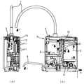
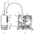
まず、従来の連続電解方式のアルカリイオン整水器について説明する。図4(a)は従来のアルカリイオン整水器の外観正面図、図4(b)は(a)のアルカリイオン整水器の外観側面図、図4(c)は(a)のアルカリイオン整水器の外観平面図、図5(a)は従来のアルカリイオン整水器本体の一部破砕構造正面図、図5(b)は(a)のアルカリイオン整水器本体の一部破砕構造の一部破砕構造側面図、図6従来のアルカリイオン整水器の反射板を示す図である。 First, a conventional continuous electrolysis type alkaline ion water conditioner will be described. 4 (a) is an external front view of a conventional alkaline ionized water device, FIG. 4 (b) is an external side view of the alkaline ionized water device of (a), and FIG. 4 (c) is an alkaline ion of (a). Fig. 5 (a) is a front view of a partially crushed structure of a conventional alkaline ionized water body, and Fig. 5 (b) is a partially crushed portion of the alkaline ionized water body of (a). FIG. 7 is a side view of a partially crushing structure of the structure, and FIG. 6 is a view showing a reflector of a conventional alkaline ionized water device.
図4(a)(b)(c)、図5(a)(b)において、1は水道水を吐水する水栓等から接続された原水管、2は水栓と原水管1で接続されたアルカリイオン整水器本体、3は原水中の残留塩素,トリハロメタン,カビ臭等を吸着する活性炭及び一般細菌や不純物を精度よく取り除く中空糸膜等を内部に備えたカートリッジ部、4は通水量の積算を検知するために設けられた流量検知手段、5はグリセロリン酸カルシウムや乳酸カルシウム等のカルシウムイオンを原水中に付与し原水導伝率を高めるカルシウム供給部、6は流量検知手段4を経由してきた水を電気分解してアルカ水、酸性水を生成する電解槽、7は電解槽6で電気分解され、アルカリイオン水及び酸性水を本体より流出する吐水管、8は電解槽6で電気分解され吐水管7からアルカリイオン水が吐出しているときには酸性水、酸性水が吐出しているときはアルカリイオン水が流出する排水管である。吐出管7および排水管8から流出される水は本体表面に設けられた操作パネル9による水質選択操作でアルカリイオン水、酸性イオン水、浄水を自在に選択するものである。原水は図中のAからアルカリイオン整水器本体2へ流入してJ方向へアルファベットの順に従って流れる。
4 (a) (b) (c) and FIGS. 5 (a) and 5 (b), 1 is a raw water pipe connected from a faucet or the like for discharging tap water, and 2 is connected by a faucet and a
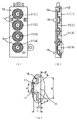
次に、従来のアルカリイオン整水器本体2からアルカリイオン水を吐水するときの光のイルミネーションについて説明する。図5(a)(b)、図6(a)(b)(c)において、10はアルカリイオン整水器本体2の表面を構成する表面パネル、11はアルカリ整水器本体2の内部に設けられた光源、12は光源11を表面パネル10に映し出す反射板である。光源11は、基板13に取り付けられ、反射板12に設けた爪14が基板13を固定している。この基板13は、反射板12に光源部が反射板12に設けたそれぞれがコーン形状の中心に配置されるように固定される。反射板12の形状は、光源11側は径が小さく、表面パネル10側に向かうに従って径が広がっている。アルカリイオン整水器に通水を行うと、水栓から接続された原水管1を通りカートリッジ3を通過して流量検知手段4へ達する。そして、流量検知手段4からの出力信号を読み取ると本体内部に備えているコントローラ(図示せず)が光源11を(1)、(2)、(3)、(4)と順番に点灯させる。そして、この複数個並べた光源11が反射板12を介して表面パネル10を透過し、複数個の光源から発する光を発光時間に時間差を設けることによって水の流れに同期させたように点灯・消灯させながら光のイルミネーション効果を出している。
以上説明したように従来のアルカリイオン整水器においては、数個並んだ光源から発する光を発光時間に時間差を設けることによって水の流れに同期した光の流れを作り出すイルミネーション効果を得ている。しかしながら、各光源から出射される光は、各反射板でコーン状に集光されて出射されるため、数個並んだ各反射板12のコーン開口部付近では明るく、隣同士の光の間では暗部が強くなりすぎ、その境がはっきりしており、水の流れに合わせた円滑な光の動きを演出するという点で課題が残るものであった。この境界でのコントラストを抑える方法としては、反射板12と表面パネル10との距離を離す方法が考えられるが、アルカリイオン整水器本体を小型にする必要があり、内部空間が十分に確保できないため距離をとることが難しい。
As described above, in the conventional alkaline ionized water device, an illumination effect is produced that creates a light flow synchronized with the flow of water by providing a time difference in the light emission time of light emitted from several light sources arranged side by side. However, since the light emitted from each light source is condensed and emitted in a cone shape by each reflecting plate, it is bright near the cone opening of each reflecting
そこで本発明は、イルミネーション効果で視覚的に滑らかな水の流れをイメージさせることができ、小型で快適に利用できるアルカリイオン整水器を提供することを目的とする。 Accordingly, an object of the present invention is to provide an alkaline ionized water device that can make a visually smooth flow of water by an illumination effect and can be used comfortably.
この課題を解決するために本発明は、水の流れに同期して発光する複数の光源と、本体表面に設けられ前記光源の光が内部から投影される光透過性または半光透過性の表示板と、光源と表示板との間に設置され、光源の光を通過させるための複数の開口が形成されるとともに表示板からの散乱光を反射する反射板が設けられたアルカリイオン整水器であって、開口の周囲にはそれぞれ反射板表面から窪んだ段差部が形成されたことを特徴とする。 In order to solve this problem, the present invention provides a plurality of light sources that emit light in synchronization with the flow of water, and a light-transmitting or semi-light-transmitting display that is provided on the surface of the main body and projects light from the light sources from the inside. An alkali ion water conditioner provided between a plate, a light source and a display plate, and having a plurality of openings for allowing light from the light source to pass therethrough and a reflecting plate for reflecting scattered light from the display plate In addition, a stepped portion that is recessed from the surface of the reflecting plate is formed around each of the openings.
本発明によれば、複数個並んだ光源の発光時間に時間差を設けることによって水の吐出に同期させた光の流れを作り出すイルミネーション効果を得ると同時に、反射板の開口付近での光のコントラストを抑えることにより、隣接する光のグラデーション効果を持たせて、滑らかな水の流れをイメージさせることができる。 According to the present invention, by providing a time difference between the light emission times of a plurality of light sources arranged side by side, an illumination effect that creates a flow of light synchronized with the discharge of water is obtained, and at the same time, the contrast of light near the opening of the reflector is reduced. By suppressing it, it is possible to give an image of smooth water flow with the gradation effect of adjacent light.
本発明の第1の形態は、水の流れに同期して発光する複数の光源と、本体表面に設けられ前記光源の光が内部から投影される光透過性または半光透過性の表示板と、光源と表示板との間に設置され、光源の光を通過させるための複数の開口が形成されるとともに表示板からの散乱光を反射する反射板が設けられたアルカリイオン整水器であって、開口の周囲にはそれぞれ反射板表面から窪んだ段差部が形成されたアルカリイオン整水器であり、複数個並んだ光源の発光時間に時間差を設けることによって水の流れに同期させた光の流れを作り出すイルミネーション効果を生じさせると同時に、反射板の開口付近での光のコントラストを抑えることにより、隣接する光のグラデーション効果を持たせて、滑らかな水の流れをイメージさせることができる。 A first aspect of the present invention is a plurality of light sources that emit light in synchronization with the flow of water, a light-transmitting or semi-light-transmitting display plate that is provided on the surface of the main body and projects light from the light sources from the inside. The alkali ion water conditioner is provided between the light source and the display plate, and is provided with a plurality of openings for allowing light from the light source to pass therethrough and a reflection plate for reflecting scattered light from the display plate. The alkali ion water conditioner is formed with stepped portions that are recessed from the surface of the reflector around the opening, and light synchronized with the flow of water by providing a time difference between the light emission times of a plurality of light sources arranged side by side. It creates an illumination effect that creates a flow of water, and at the same time suppresses the contrast of the light near the aperture of the reflector, thereby giving a gradation effect of adjacent light and making a smooth water flow image It can be.
本発明の第2の形態は、第1の形態に従属する形態であって、段差部の表示板側の直径B、開口の直径A、光源の入射角θ及び段差の深さCの間に、B>2C/tanθ+Aの関係があるアルカリイオン整水器であり、反射板の開口付近での光のコントラストを確実に抑えることができ、隣接する光のグラデーション効果で滑らかな水の流れをイメージさせることができる。 The second form of the present invention is a form subordinate to the first form, and is between the diameter B on the display plate side of the stepped portion, the diameter A of the opening, the incident angle θ of the light source, and the depth C of the stepped portion. , B> 2C / tanθ + A alkaline ion water conditioner, can reliably suppress the contrast of light near the opening of the reflector, and image the smooth water flow with the gradation effect of adjacent light Can be made.
本発明の第3の形態は、第2の形態に従属する形態であって、段差部の深さCが、表示板と光源の間の距離Lに対しC≦Lの関係にあるアルカリイオン整水器であり、反射板の開口付近での光のコントラストをさらに確実に抑えることができ、隣接する光のグラデー
ション効果で滑らかな水の流れをイメージさせることができる。
A third form of the present invention is a form subordinate to the second form, wherein the depth C of the stepped portion is an alkaline ion arrangement in which C ≦ L with respect to the distance L between the display panel and the light source. It is a water container, and the contrast of light in the vicinity of the opening of the reflecting plate can be more reliably suppressed, and a smooth water flow can be imaged by the gradation effect of adjacent light.
本発明の第4の形態は、第1の形態に従属する形態であって、段差部と開口の間に、光源側の直径が小さく表示板側の直径が大きいコーン状傾斜部が設けられたアルカリイオン整水器であり、複数個並んだ光源の発光時間に時間差を設けることによって水の流れに同期させた光の流れを作り出すイルミネーション効果を生じさせると同時に、反射板の中央に光を集光し中央と反射板の周縁部とのコントラストを強くすることで、反射板の開口付近での光のコントラストを抑え、隣接する光のグラデーション効果を持たせて、滑らかな水の流れをイメージさせることができる。 The fourth form of the present invention is a form dependent on the first form, and a cone-shaped inclined part having a small diameter on the light source side and a large diameter on the display panel side is provided between the step part and the opening. This is an alkali ion water conditioner. By providing a time difference between the light emission times of a plurality of light sources arranged side by side, an illumination effect that creates a light flow synchronized with the flow of water is produced, and at the same time, the light is collected at the center of the reflector. Increasing the contrast between the center of light and the peripheral edge of the reflector suppresses the contrast of light near the reflector opening and gives the effect of gradation of adjacent light to create a smooth flow of water be able to.
本発明の第5の形態は、第4の形態に従属する形態であって、段差部の直径がコーン状傾斜部の表示側の直径より大きいアルカリイオン整水器であり、複数個並んだ光源の発光時間に時間差を設けることによって水の吐出に同期させた光の流れを作り出すイルミネーション効果を得ると同時に、反射板の開口付近での光のコントラストを抑え、隣接する光のグラデーション効果を持たせて、滑らかな水の流れをイメージさせることができる。 A fifth aspect of the present invention is an alkaline ion water conditioner according to the fourth aspect, wherein the stepped portion has a diameter larger than the diameter on the display side of the cone-shaped inclined portion, and a plurality of light sources arranged side by side. By providing a time difference in the light emission time, the illumination effect that creates a light flow synchronized with the discharge of water is obtained, and at the same time, the contrast of light near the aperture of the reflector is suppressed and the gradation effect of adjacent light is given. And you can imagine a smooth flow of water.
本発明の第6の形態は、第5の形態に従属する形態であって、段差部の直径Bが、コーン先端の直径Dに対しコーンの表示板への入射角θと段差の深さCがB>2C/tanθ+Dの関係にあるアルカリイオン整水器であり、反射板の開口付近での光のコントラストを確実に抑えることができ、隣接する光のグラデーション効果で滑らかな水の流れをイメージさせることができる。 The sixth form of the present invention is a form dependent on the fifth form, and the diameter B of the stepped portion is the incident angle θ to the display panel of the cone and the depth C of the step with respect to the diameter D of the cone tip. Is an alkaline ionized water conditioner that has a relationship of B> 2C / tanθ + D, which can reliably suppress the contrast of light near the opening of the reflector, and image the smooth water flow by the gradation effect of adjacent light Can be made.
本発明の第7の形態は、第6の形態に従属する形態であって、段差部の深さCが、表示板と光源の間の距離Lに対しC<Lの関係にあるアルカリイオン整水器であり、反射板の開口付近での光のコントラストをさらに確実に抑えることができ、隣接する光のグラデーション効果で滑らかな水の流れをイメージさせることができる。 A seventh aspect of the present invention is an aspect dependent on the sixth aspect, wherein the depth C of the stepped portion is an alkali ion control in which C <L with respect to the distance L between the display panel and the light source. It is a water container, and the contrast of light in the vicinity of the opening of the reflecting plate can be more reliably suppressed, and a smooth water flow can be imaged by the gradation effect of adjacent light.
(実施の形態1)
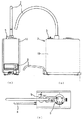
以下、本発明の実施の形態1のアルカリイオン整水器について図面を用いて説明する。図1(a)は本発明の実施の形態1におけるアルカリイオン整水器の構造側面図、図1(b)は(a)のアルカリイオン整水器本体の一部破砕構造正面図である。図1(a)(b)において、従来例の説明で用いた符号と同一符号のものは本実施の形態1においても基本的に同一であるため、詳細な説明は従来例のところに譲って省略する。
(Embodiment 1)
Hereinafter, an alkaline ionized water apparatus according to
図1(a)(b)に示すように、1は水道水を吐水する水栓等から接続された原水管、2は水栓等と原水管1で接続されたアルカリイオン整水器本体、3は内部に原水中の残留塩素、トリハロメタン、カビ臭等を吸着する活性炭及び一般細菌や不純物を精度よく取り除く中空糸膜等を備えたカートリッジ部、4は通水量の積算を検知するために設けられた流量検知手段、5はグリセロリン酸カルシウムや乳酸カルシウム等のカルシウムイオンを原水中に付与し原水導伝率を高めるカルシウム供給部、6は流量検知手段4を経由してきた水を電気分解してアルカ水、酸性水を生成する電解槽、7は電解槽6で電気分解され、アルカリイオン水及び酸性水を本体より流出する吐水管、8は電解槽6で電気分解され吐水管7からアルカリイオン水が吐出しているときには酸性水、酸性水が吐出しているときはアルカリイオン水が流出する排水管である。吐出管7および排水管8から流出される水は本体表面に設けられた操作パネル9による水質選択操作でアルカリイオン水、酸性イオン水、浄水を自在に選択することができる。10は後述する光源11から出射された光をアルカリイオン整水器本体2内部から投影する表面パネルであり、光透過性または半光透過性の樹脂から構成される。
As shown in FIGS. 1 (a) and 1 (b), 1 is a raw water pipe connected from a faucet or the like for discharging tap water, 2 is an alkali ion water conditioner main body connected to the faucet or the like by the
アルカリイオン整水器に通水を行うと、水栓から接続された原水管1を通りカートリッ
ジ3を通過して、CからDに流れる間にカートリッジ部3の中空糸膜等で不純物を除去され、Eの流量検知手段4へ達する。そして、流量検知手段4からの出力信号を読み取ると本体内部に備えているコントローラ(図示せず)が光源11を(1)、(2)、(3)、(4)と順番に点灯させる。そして、この複数個並べた光源11が反射板12を介して表面パネル10を透過し、複数個の光源から発する光を発光時間に時間差を設けることによって水の流れに同期させて点灯・消灯させながら光のイルミネーション効果を得るものである。そしてGからH,Iを流れる間に電解槽6内で電気分解され、吐水管7からJの方向にアルカリイオン水または酸性水を吐出し、排水管8からは吐出する必要がないイオン水が排水される。なお、本発明において水の流れに同期させるとは、流量検知手段4からの出力信号を読み取ってコントローラにより光源11を流れの速度に合わせて順番に点灯させることをいう。また、所定以上の流量を流量検知手段4が検知した場合に、コントローラにより光源11を流れの速度に合わせて順番に点灯させてもよい。即ち、きわめて少ない流量の場合は、非点灯ととして省電力を図ってもよい。
When water is passed through the alkaline ionized water device, impurities are removed by the hollow fiber membrane or the like of the
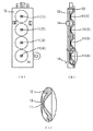
次に、本発明の実施の形態1のアルカリイオン整水器本体2の内部に備えられている光源11と反射板12について説明する。図2(a)は本発明の実施の形態1におけるアルカリイオン整水器に内蔵されている反射板の正面図、図2(b)は(a)の反射板の断面図、図2(c)は(b)の反射板の部分拡大図である。図2(a)(b)(c)において、11は光源、12は反射板、13は基板、14は爪である。そして15は反射板12の表面パネル10側の表面に設けられた開口部、16は開口部15に形成された段差部、17は開口部15の中央に形成された円筒形の開口である。開口部15は複数個並んで設けられ、底面が段差部16の穴であり、この中央にそれぞれ開口17が形成される。
Next, the
光源11は基板13に取り付けられており、反射板12に設けた爪14が基板13を固定している。このとき、光源11が各開口部15の中心(開口17の中心)に一致するように、基板13が反射板12の所定位置に固定される。段差部16の形状は、光源11を覆う円筒形の開口17の直径をA、段差部16の直径をB、段差部16の深さをC、光源11から表面パネル10への光の入射角をθとすると、図2(c)に示すように、B>2C/tanθ+Aとなる。
The
この形状にすることにより、図2(a)のSで表す部分は明るい部分からの光が散光し、暗くすることができる。このとき段差部16の深さCは、光源11から反射板12の先端部(表面パネル10側)までの距離をLとするとC≦Lであればどの深さでもよい。
By adopting this shape, the light represented by S in FIG. 2A can be darkened by scattering light from the bright part. At this time, the depth C of the stepped
このように実施の形態1のアルカリイオン整水器は、複数個並んだ光源11の発光時間に時間差を設けることによって、水の吐出に同期させた光の流れを作り出すイルミネーション効果を生じさせると同時に、光源11からの光を表面パネル10側に反射させる反射板12の開口部15に段差部16を設けて図2(c)に示す光のコーン状の部分とそれ以外の部分との光量の差を少なくし、原水の流れにグラデーション効果を実現することができ、表面パネル10を見ることで滑らかな水の流れをイメージさせることができる。
As described above, the alkali ion water conditioner of
(実施の形態2)
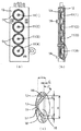
本発明の実施の形態2のアルカリイオン整水器について図面を用いて説明する。図3(a)は本発明の実施の形態2におけるアルカリイオン整水器に内蔵されている反射板の正面図、図3(b)は(a)の反射板の断面図、図3(c)は(b)の反射板の部分拡大図である。図3(a)(b)(c)において、11は光源、12は反射板、13は基板、14は爪、15は開口部、16は段差部、17は開口、18は開口部15の中央に形成されたコーン形状のコーン状傾斜部である。
(Embodiment 2)
The alkaline ionized water apparatus of
実施の形態2のアルカリイオン整水器の基本的な構成は実施の形態1と同様であり、光
源11は基板13に取り付けられ、この基板13は反射板12に設けた爪14によって固定される。このとき、光源11がそれぞれコーン形状のコーン状傾斜部18の中心に位置するように固定される。コーン状傾斜部18の形状は、光源11側では径が小さく、表面パネル10側に向かうに従い径が広がっている。そして表面パネル10側の開口部15には、その開口径よりさらに広い直径をもつ段差部16が設けられる。
The basic configuration of the alkaline ionized water device of the second embodiment is the same as that of the first embodiment, and the
この段差部16は、段差部16の直径をB、コーン形状のコーン状傾斜部18の最大径をD、コーン状傾斜部18の広がり角度をθと表すとB>2C/tanθ+Dで表される。この形状にすることにより、図2(a)のSで示す部分は明るい部分からの光が散り、暗くすることができる。このとき段差部16の深さCは、光源11から反射板12の先端部(表面パネル側)までの距離をLとするとC<Lであればどのような深さでもよい。
The
このように実施の形態2のアルカリイオン整水器は、複数個並んだ光源11の発光時間に時間差を設けることによって、水の吐出に同期させた光の流れを作り出すイルミネーション効果を得ると同時に、光源11からの光を表面パネル10側に反射させる反射板12の開口部15にコーン状傾斜部18と段差部16を設け、反射板12の中央に光を集光し中央と反射板12の周縁部とのコントラストを強くすることで、反射板12の開口付近での光のコントラストを抑え、原水の流れにグラデーション効果を実現することができ、表面パネル10を見ることで滑らかな水の流れをイメージさせることができる。
As described above, the alkaline ionized water device of the second embodiment obtains an illumination effect that creates a flow of light synchronized with the discharge of water by providing a time difference in the light emission times of the
本発明のアルカリイオン整水器は、飲用,医療用として利用するアルカリイオン水、あるいは化粧水,殺菌洗浄水等として利用する酸性イオン水を製造し、且つ視覚的に滑らかな水の流れをイメージさせることでこれらのイオン水を快適に利用するアルカリイオン整水器等に利用することができる。 The alkaline ionized water device of the present invention produces alkaline ionized water used for drinking and medical use, or acidic ionized water used for lotion, sterilizing washing water, etc., and has an image of visually smooth water flow. By making it, it can utilize for the alkali ion water conditioner etc. which utilize these ion water comfortably.
1 原水管
2 アルカリイオン整水器本体
3 カートリッジ部
4 流量検知手段
5 カルシウム供給部
6 電解槽
7 吐水管
8 排水管
9 操作パネル
10 表面パネル
11 光源
12 反射板
13 基板
14 爪
15 開口部
16 段差部
17 開口
18 コーン状傾斜部
DESCRIPTION OF
Claims (8)
Priority Applications (1)
| Application Number | Priority Date | Filing Date | Title |
|---|---|---|---|
| JP2004117611A JP4586401B2 (en) | 2004-04-13 | 2004-04-13 | Alkaline ion water conditioner |
Applications Claiming Priority (1)
| Application Number | Priority Date | Filing Date | Title |
|---|---|---|---|
| JP2004117611A JP4586401B2 (en) | 2004-04-13 | 2004-04-13 | Alkaline ion water conditioner |
Publications (2)
| Publication Number | Publication Date |
|---|---|
| JP2005296831A true JP2005296831A (en) | 2005-10-27 |
| JP4586401B2 JP4586401B2 (en) | 2010-11-24 |
Family
ID=35329024
Family Applications (1)
| Application Number | Title | Priority Date | Filing Date |
|---|---|---|---|
| JP2004117611A Expired - Fee Related JP4586401B2 (en) | 2004-04-13 | 2004-04-13 | Alkaline ion water conditioner |
Country Status (1)
| Country | Link |
|---|---|
| JP (1) | JP4586401B2 (en) |
Citations (7)
| Publication number | Priority date | Publication date | Assignee | Title |
|---|---|---|---|---|
| JPH0440277U (en) * | 1990-08-01 | 1992-04-06 | ||
| JPH04337790A (en) * | 1991-05-15 | 1992-11-25 | Matsushita Electric Ind Co Ltd | Controller for electric equipment |
| JP2001070942A (en) * | 1999-09-07 | 2001-03-21 | Nippon Intek Kk | Electrolytic water generator |
| JP2001087766A (en) * | 1999-09-21 | 2001-04-03 | Nippon Intek Kk | Multifunctional electrolytic water production device |
| JP2002210464A (en) * | 2001-01-18 | 2002-07-30 | Matsushita Electric Works Ltd | Electrolyzed water generation apparatus |
| JP2002210463A (en) * | 2001-01-18 | 2002-07-30 | Matsushita Electric Works Ltd | Electrolyzed water generation apparatus |
| JP2004057856A (en) * | 2002-07-25 | 2004-02-26 | Sharp Corp | Ion elution unit and washing machine with the same mounted thereon |
-
2004
- 2004-04-13 JP JP2004117611A patent/JP4586401B2/en not_active Expired - Fee Related
Patent Citations (7)
| Publication number | Priority date | Publication date | Assignee | Title |
|---|---|---|---|---|
| JPH0440277U (en) * | 1990-08-01 | 1992-04-06 | ||
| JPH04337790A (en) * | 1991-05-15 | 1992-11-25 | Matsushita Electric Ind Co Ltd | Controller for electric equipment |
| JP2001070942A (en) * | 1999-09-07 | 2001-03-21 | Nippon Intek Kk | Electrolytic water generator |
| JP2001087766A (en) * | 1999-09-21 | 2001-04-03 | Nippon Intek Kk | Multifunctional electrolytic water production device |
| JP2002210464A (en) * | 2001-01-18 | 2002-07-30 | Matsushita Electric Works Ltd | Electrolyzed water generation apparatus |
| JP2002210463A (en) * | 2001-01-18 | 2002-07-30 | Matsushita Electric Works Ltd | Electrolyzed water generation apparatus |
| JP2004057856A (en) * | 2002-07-25 | 2004-02-26 | Sharp Corp | Ion elution unit and washing machine with the same mounted thereon |
Also Published As
| Publication number | Publication date |
|---|---|
| JP4586401B2 (en) | 2010-11-24 |
Similar Documents
| Publication | Publication Date | Title |
|---|---|---|
| JP2009154030A (en) | Electrolytic water generating and spraying device | |
| FR2883008B1 (en) | PROCESS FOR THE JOINT PRODUCTION OF CHLORINE AND CRYSTALS OF CARBONATE MONOHYDRATE | |
| JP2008168237A (en) | Ionized alkaline water producing machine | |
| KR200393066Y1 (en) | Sterilizer of Ionizer | |
| JP4086311B2 (en) | Reduced hydrogen water generator | |
| JP4586401B2 (en) | Alkaline ion water conditioner | |
| JP2010131545A (en) | Water treatment apparatus | |
| JP2007308764A (en) | Dissolve oxygen water-producing apparatus | |
| JP5359395B2 (en) | Air cleaner | |
| JP2004230261A (en) | Reduced hydrogen water producing apparatus | |
| CN205138998U (en) | Liquid colour data acquisition signal enhancement ware | |
| JP4936423B2 (en) | Electrolyzed water generating device and sink equipped with the same | |
| JP2018042594A (en) | Washstand | |
| JP3882509B2 (en) | Electrolyzed water generator | |
| JP3991995B2 (en) | Electrolyzed water generator | |
| JP3991994B2 (en) | Electrolyzed water generator | |
| KR200327034Y1 (en) | Detecting Device For Hot Water Of Ion Purifier | |
| JP3835173B2 (en) | Electrolyzed water generator | |
| JP7488132B2 (en) | Electrolyzed water generator | |
| JP2018080481A (en) | Water section appliance | |
| JP7488131B2 (en) | Electrolyzed water generator | |
| KR101630876B1 (en) | A water ionizer | |
| JP2011094413A (en) | Washing device | |
| KR101212835B1 (en) | bidet | |
| JP2011183011A (en) | Air purifier and electrolytic mist generator |
Legal Events
| Date | Code | Title | Description |
|---|---|---|---|
| A711 | Notification of change in applicant |
Free format text: JAPANESE INTERMEDIATE CODE: A711 Effective date: 20070316 |
|
| A521 | Written amendment |
Free format text: JAPANESE INTERMEDIATE CODE: A821 Effective date: 20070322 |
|
| RD02 | Notification of acceptance of power of attorney |
Free format text: JAPANESE INTERMEDIATE CODE: A7422 Effective date: 20070322 |
|
| A621 | Written request for application examination |
Free format text: JAPANESE INTERMEDIATE CODE: A621 Effective date: 20070323 |
|
| A977 | Report on retrieval |
Free format text: JAPANESE INTERMEDIATE CODE: A971007 Effective date: 20091217 |
|
| A131 | Notification of reasons for refusal |
Free format text: JAPANESE INTERMEDIATE CODE: A131 Effective date: 20100112 |
|
| A521 | Written amendment |
Free format text: JAPANESE INTERMEDIATE CODE: A523 Effective date: 20100315 |
|
| RD04 | Notification of resignation of power of attorney |
Free format text: JAPANESE INTERMEDIATE CODE: A7424 Effective date: 20100629 |
|
| TRDD | Decision of grant or rejection written | ||
| A01 | Written decision to grant a patent or to grant a registration (utility model) |
Free format text: JAPANESE INTERMEDIATE CODE: A01 Effective date: 20100810 |
|
| A01 | Written decision to grant a patent or to grant a registration (utility model) |
Free format text: JAPANESE INTERMEDIATE CODE: A01 |
|
| A61 | First payment of annual fees (during grant procedure) |
Free format text: JAPANESE INTERMEDIATE CODE: A61 Effective date: 20100823 |
|
| FPAY | Renewal fee payment (prs date is renewal date of database) |
Free format text: PAYMENT UNTIL: 20130917 Year of fee payment: 3 |
|
| LAPS | Cancellation because of no payment of annual fees |