JP2005296742A - Twin-shaft shearing cutter apparatus for used tire - Google Patents
Twin-shaft shearing cutter apparatus for used tire Download PDFInfo
- Publication number
- JP2005296742A JP2005296742A JP2004114090A JP2004114090A JP2005296742A JP 2005296742 A JP2005296742 A JP 2005296742A JP 2004114090 A JP2004114090 A JP 2004114090A JP 2004114090 A JP2004114090 A JP 2004114090A JP 2005296742 A JP2005296742 A JP 2005296742A
- Authority
- JP
- Japan
- Prior art keywords
- tire
- cutter
- hopper
- cutting
- cutters
- Prior art date
- Legal status (The legal status is an assumption and is not a legal conclusion. Google has not performed a legal analysis and makes no representation as to the accuracy of the status listed.)
- Pending
Links
- 238000010008 shearing Methods 0.000 title abstract description 14
- 239000010920 waste tyre Substances 0.000 description 8
- 125000006850 spacer group Chemical group 0.000 description 3
- 239000003638 chemical reducing agent Substances 0.000 description 2
- 239000003245 coal Substances 0.000 description 2
- 239000000446 fuel Substances 0.000 description 2
- 239000002699 waste material Substances 0.000 description 2
- 238000002485 combustion reaction Methods 0.000 description 1
- 238000006073 displacement reaction Methods 0.000 description 1
- 230000007613 environmental effect Effects 0.000 description 1
- 239000000295 fuel oil Substances 0.000 description 1
- 230000002787 reinforcement Effects 0.000 description 1
- 239000011343 solid material Substances 0.000 description 1
Images


Landscapes
- Filling Or Emptying Of Bunkers, Hoppers, And Tanks (AREA)
- Crushing And Pulverization Processes (AREA)
Abstract
Description
本発明は古タイヤを細かく砕くことが出来る2軸せん断カッター装置に関するものである。 The present invention relates to a biaxial shear cutter device capable of finely crushing old tires.
車社会である今日、大量の用済タイヤ(廃タイヤ)が発生し、この廃タイヤの処理が大きな環境問題と成っている。そこで、この廃タイヤの処理対策の1つとして燃料としての利用が行われ、重油や石炭の代わりに用いられる。コスト的にも若干安くなり、燃焼効率も決して悪くはないが、大きなタイヤをそのままの形状にて使用することは出来ず、また、廃タイヤそのままの形態では運搬や保管が困難であることから、細かく切断されている。 Today, as a car society, a large amount of used tires (waste tires) are generated, and the disposal of the waste tires has become a major environmental problem. Therefore, as one of the measures for treating the waste tire, it is used as a fuel and used instead of heavy oil or coal. Although it is slightly cheaper in terms of cost and combustion efficiency is not bad, it is not possible to use a large tire as it is, and it is difficult to transport and store in the form of waste tire as it is, Finely cut.
細かくすることで石炭の運搬や保管と同じように取り扱うことが可能となって、廃タイヤの燃料としての利用が便利となる。そこで、該廃タイヤは細かく切断されることになるが、この廃タイヤ切断装置としては実開昭57−101022号に係る「ゴムタイヤその他の固形物用裁断機」が知られている。この裁断機は刃物基体の下面に放射状に配列して取着した多数のブレードを設けてタイヤを押圧・切断する構造と成っている訳で、ブレードの押圧は油圧シリンダーの作動で行われる。 By making it finer, it can be handled in the same way as transporting and storing coal, and it is convenient to use waste tires as fuel. Therefore, the waste tire is cut finely. As this waste tire cutting device, a "rubber tire and other solid material cutting machine" according to Japanese Utility Model Laid-Open No. 57-101022 is known. This cutting machine has a structure in which a large number of blades arranged and attached in a radial pattern are provided on the lower surface of the blade base to press and cut the tire, and the pressing of the blade is performed by the operation of a hydraulic cylinder.
すなわち、上フレームに油圧シリンダーを備え、刃物基体は油圧シリンダーのピストンロッド端に取着し、ピストンロッドが伸びるならば刃物基体並びにブレードが降下して収容ベースに置かれている廃タイヤを切断する。しかし、この裁断機は油圧シリンダーが作動してブレードが昇降動することで古タイヤが押圧・切断される為に、連続した切断作業は出来ない為に、作業能率は決して高くない。 That is, the upper frame is provided with a hydraulic cylinder, the blade base is attached to the end of the piston rod of the hydraulic cylinder, and if the piston rod extends, the blade base and the blade are lowered to cut the waste tire placed on the storage base. . However, this cutting machine has a high working efficiency because the old cylinder is pressed and cut by the hydraulic cylinder operating and the blades moving up and down, so that continuous cutting cannot be performed.
そこで、回転する2軸に切断カッターを取着し、回転する両軸の間に古タイヤを挿入するならば、切断カッターに噛み込んで切断される。しかも、断続的な動作ではなく連続して切断が行われる。例えば、特開2003−144955号に係る「せん断式破砕機」は、駆動軸の軸方向にスペーサを挟んで複数の刃物取付け台を設け、この刃物取付け台の周方向に複数の切断刃を取付ける刃物取付け面を形成し、前記スペーサの縁部をこの刃物取付け面から所定の段差分で突出させて前記切断刃の基部を支持し、この支持した切断刃の少なくとも1個の前記段差分が接する位置の前記スペーサに、この切断刃を軸方向に移動させて取外しさせるようにする着脱部分を設けて、切断刃の交換作業を迅速に行えるようにしている。 Therefore, if a cutting cutter is attached to two rotating shafts and an old tire is inserted between both rotating shafts, the cutting cutter is engaged with the cutting cutter and cut. Moreover, cutting is performed continuously, not intermittently. For example, a “shearing crusher” according to Japanese Patent Application Laid-Open No. 2003-144955 is provided with a plurality of blade mounting bases with spacers in the axial direction of a drive shaft, and a plurality of cutting blades are attached in the circumferential direction of the blade mounting base. A blade attachment surface is formed, the edge of the spacer is protruded from the blade attachment surface by a predetermined step to support the base of the cutting blade, and at least one step of the supported cutting blade contacts The spacer at the position is provided with an attaching / detaching portion for moving the cutting blade in the axial direction and removing it so that the cutting blade can be replaced quickly.
特開2001−205124号に係る「二軸せん断式破砕機用切断刃」は、互いに対向して回転する切断刃の先端部を、対向する切断刃の間で被処理物Wをせん断できる隙間を有す幅で形成し、基部を対向して回転する切断刃との間に間隙幅が形成できる幅に形成して、切断刃で破砕した被処理物Wを切断刃の間に詰まられることなく破砕機から排出できるようにしている。 The “cutting blade for a biaxial shearing crusher” according to Japanese Patent Application Laid-Open No. 2001-205124 has a gap that can shear the workpiece W between the opposing cutting blades at the tip of the cutting blades that rotate opposite to each other. The width of the workpiece W is formed so that a gap width can be formed between the cutting blade and the rotating blade facing the base, and the workpiece W crushed by the cutting blade is not clogged between the cutting blades. It can be discharged from the crusher.
これらの他に二軸せん断カッター装置は色々あり、特開2004−66226号に係る「二軸せん断式破砕機の回転刃」、特開平11−114440号に係る「せん断破砕機の回転刃取付構造」、特許第2911403号に係る「二軸せん断式破砕機の回転刃」などが知られている。しかし、上記二軸せん断式破砕機を用いて古タイヤを細かく切断する場合、回転する回転刃にかみこむことが出来ず、切断作業の能率が低下してしまう。
このように従来の2軸せん断カッター装置には上記のごとき問題がある。本発明が解決しようとする課題はこの問題点であり、古タイヤを細かくせん断することが出来、しかも能率良く切断し得る2軸せん断カッター装置を提供する。 Thus, the conventional biaxial shear cutter apparatus has the above-described problems. The problem to be solved by the present invention is this problem, and provides a biaxial shear cutter apparatus that can shear old tires finely and that can cut efficiently.
本発明に係る2軸せん断カッター装置は、リング状のカッターベースに複数のカッターが取着される。カッターベースにはノコ歯状の取付け面が形成され、該取付け面にブロック状のカッターが固定される。ここで、カッターの幅寸法はカッターベースの幅寸法より僅かに大きく成っていて、両軸のカッターが互いに噛合わされた場合に、カッターベースの側面との間には僅かな隙間が残って接することはなく、この隙間はタイヤ切断屑の逃がしとなる。 In the biaxial shear cutter device according to the present invention, a plurality of cutters are attached to a ring-shaped cutter base. A sawtooth mounting surface is formed on the cutter base, and a block-shaped cutter is fixed to the mounting surface. Here, the width dimension of the cutter is slightly larger than the width dimension of the cutter base, and when the cutters of both shafts are engaged with each other, a slight gap remains between the side surfaces of the cutter base. There is no clearance between the tire cutting scraps.
そして、本発明の2軸せん断カッター装置はホッパーを有し、該ホッパー内にはタイヤプッシャーを取付けている。該タイヤプッシャーはシリンダーの作動でガイドに沿って摺動し、ホッパーに投入した古タイヤを回転する切断カッター軸に押付けて噛み込ませることが出来る。 And the biaxial shear cutter apparatus of this invention has a hopper, The tire pusher is attached in this hopper. The tire pusher slides along the guide by the operation of the cylinder, and the old tire thrown into the hopper can be pressed against the rotating cutting cutter shaft to be engaged.
本発明に係る2軸せん断カッター装置は、カッターベースに形成した取付け面に複数のブロック状カッターを取着している。そして、カッターの幅はカッターベースより僅かに大きく成っている為に、互いに噛合ったカッターとカッターベース間には隙間が形成される。従って、噛合ったカッター間に挟まったタイヤ切断屑は上記隙間に逃げることが出来、固定されているカッターを位置ズレさせることはない。 The biaxial shear cutter device according to the present invention has a plurality of block cutters attached to an attachment surface formed on a cutter base. Since the width of the cutter is slightly larger than the cutter base, a gap is formed between the cutter and the cutter base that are engaged with each other. Therefore, the tire cutting waste caught between the engaged cutters can escape into the gap, and the fixed cutter is not displaced.
一方、本発明の2軸せん断カッター装置はタイヤプッシャーを備えている。従って、如何なるサイズのタイヤであっても、該タイヤプッシャーによって押圧することで回転する切断カッター軸に噛み込むことで切断することが可能と成る。勿論、ホッパーへ投入すると共に、切断カッター軸に噛み込むことの出来るタイヤの場合には、上記プッシャーを作動させる必要はないが、モーターの負荷を検出することでタイヤの噛み込みの有無を知ることが可能である。 On the other hand, the biaxial shear cutter device of the present invention includes a tire pusher. Therefore, any size tire can be cut by being bitten by the rotating cutting cutter shaft by being pressed by the tire pusher. Of course, in the case of a tire that can be put into the hopper and bitten into the cutting cutter shaft, it is not necessary to operate the above pusher, but knowing whether the tire is bitten by detecting the motor load Is possible.
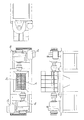
図1は本発明の2軸せん断カッター装置の外観を示す実施例であり、同図の1はホッパー、2a,2bはモーターを示している。上記ホッパー内には2本の切断カッター軸3a,3bが取着されていて、各々の切断カッター軸3a,3bは別々のモーター2a,2bによって回転駆動される。勿論、1個のモーターでもって2本の切断カッター軸3a,3bを回転駆動するように構成することに何ら問題はない。
FIG. 1 shows an embodiment of the external appearance of the biaxial shear cutter device of the present invention. In FIG. 1, 1 indicates a hopper, and 2a and 2b indicate motors. Two
上記モーター2aと切断カッター軸3aとの間には減速機4aが設けられて、モーター2aの回転速度が落とされて切断カッター軸3aは回転することが出来る。同じく、上記モーター2bと切断カッター軸3bとの間には減速機4bが設けられて、モーター2bの回転速度が落とされて切断カッター軸3bは回転することが出来る。ここで、両切断カッター軸3a,3bの回転速度は同一と成っているが、僅かに違っても古タイヤを切断するに際して大きな問題はない。
A
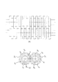
図2は上記切断カッター軸3a,3bを示している。切断カッター軸3a,3bには複数のカッター5a,5a・・、5b,5b・・が取着されていて、各カッター5a,5a・・、5b,5b・・は等間隔で配列されている。切断カッター軸3aはスプライン軸6aと複数のカッターベース7a,7a・・、及び複数のカラー8a,8a・・から成り、スプライン軸6aにはカッターベース7aとカラー8aが交互に取付けられている。
FIG. 2 shows the
カッターベース7aの厚さ、及びカラー8aの厚さは均一化され、従ってカッターベース7a,7a・・は間にカラー8a,8a・・を介在することでカッターベース7a,7a・・は等間隔で配列されることになる。同じく、切断カッター軸3bの場合も、スプライン軸6bにはカッターベース7b,7b・・がカラー8b,8b・・を間に介在することで等間隔に配列されている。
The thickness of the cutter base 7a and the thickness of the collar 8a are made uniform, so that the cutter bases 7a, 7a,. Will be arranged. Similarly, in the case of the
上記カッターベース7a,7bはカラー8a,8bよりその外径は大きく、外周にはノコ歯状の取付け面が全周にわたって形成され、このノコ歯状の取付け面にカッター5a,5a・・、及びカッター5b、5b・・がネジ止めにて取着されている。カッター5a,5a・・、5b、5b・・は適度なすくい角をもって傾斜し、隣り合うカッター5a,5a・・、5b,5b・・との間には適度な段差A,A・・を有している。
The cutter bases 7a and 7b have a larger outer diameter than the collars 8a and 8b, and a saw-tooth mounting surface is formed on the outer periphery over the entire circumference, and the
図2(a)から明らかなように、切断カッター軸3aに取着されているカッター5a,5a・・と切断カッター軸3bに取着されているカッター5b,5b・・とは、互いに噛合うことが出来るように軸方向に1ピッチ分ズレて取着され、カッター5aと5a間の空間にカッター5bが噛合うことが出来る。両切断カッター軸の回転に伴って、各カッター5a,5b・・が同図の(b)に示すように噛合うことで、間に挟まれる古タイヤは切断される。
As is clear from FIG. 2 (a), the
ここで、図3に示すように、カッター5a,5b・・は間に隙間を発生することなく噛合うことにしているが、カッターベース7a,7bとの間には隙間を残している。すなわち、カッターベース7a,7bは外周にノコ歯状の取付け面を形成したリング体であって、その厚さはカッター5a,5b・・より小さく成っている。
Here, as shown in FIG. 3, the
従って、カッターベース7a,7bと各カッター5a,5b・・との間には僅かな段差が残され、カッター5a,5b・・が噛合った際にはカッターベース間に隙間が形成され、古タイヤの細かい切断屑はカッター5a,5b・・とカッターベース7a,7b間の隙間から逃がされる。この為に、カッターベース7a,7bの取付け面にネジ止めにて固定されているカッター5a,5b・・の位置ズレは発生せず、切れの低下を招かない。
Therefore, a slight step is left between the cutter bases 7a, 7b and the
ところで、上記切断カッター軸3a,3bはホッパー1の内部下方に設けられ、該ホッパー1に投入される古タイヤは両切断カッター軸3a,3bに噛み込まれて細かく切断される。そして、切断されたタイヤ片は切断カッター軸3a,3bから落下して排出される。ホッパー1に投入される古タイヤは、切断カッター軸3a,3bに噛み込むことになるが、古タイヤのサイズや種類によっては、単に投入しただけでは噛み込むことが出来ない場合が発生する為に、本発明ではタイヤプッシャー装置を備えている。
By the way, the
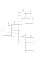
図4、図5は上記タイヤプッシャー装置を示す具体例である。タイヤプッシャー装置は、タイヤプッシャー9とシリンダー10、及びガイドシャフト11を有し、タイヤプッシャー9はホッパー1のほぼ全幅に跨り、両側端にはスライダー12,12を設け、該スライダー12,12は上記ガイドシャフト11,11にガイドされてスライド可能と成っている。シリンダー10,10はホッパー1の両外側に配置され、シリンダー10,10のピストンロッド先端はスライダー12,12に連結している。
4 and 5 are specific examples showing the tire pusher device. The tire pusher device includes a
タイヤプッシャー9は長方形の板材に補強を所々に設けたものであり、ホッパー1の外側に位置するスライダー12,12と連結する繋ぎ部13,13が移動する為のスライド溝14,14をホッパーの側部に設けている。図4において(a)はシリンダー10のピストンロッドが収縮してタイヤプッシャー9が下方にある場合、(b)はシリンダー10のピストンロッドが伸長してタイヤプッシャー9が上方にある場合を示している。
The
図5は、タイヤプッシャー9のスライダー12の位置とシリンダー10の関係を示す側面図である。シリンダー10は揺動可能に取付けられている為に、タイヤプッシャー9のスライドに伴ってその向きを変えることが出来る。図6はホッパー1に投入された古タイヤ15がタイヤプッシャー9に押されて切断カッター軸3a,3bに噛み込まれる場合を示している。古タイヤ15は左側から投入されるために、左側には傾斜面16を設け、該タイヤプッシャー9にて押圧し易いようにしている。
FIG. 5 is a side view showing the relationship between the position of the
タイヤプッシャー装置は常に作動する必要はなく、切断カッター軸3a,3bに噛み込まない場合に投入されたタイヤ15を上方から押圧する。そこで、タイヤ投入後にモーター2a,2bの負荷が上昇しないようであれば、タイヤ15が切断カッター軸3a,3bに噛み込んでいないと判断して、タイヤプッシャー装置が作動するように制御している。
The tire pusher device does not always have to operate, and presses the
1 ホッパー
2 モーター
3 切断カッター軸
4 減速機
5 カッター
6 スプライン軸
7 カッターベース
8 カラー
9 タイヤプッシャー
10 シリンダー
11 ガイドシャフト
12 スライダー
13 繋ぎ部
14 スライド溝
15 古タイヤ
16 傾斜面
1 Hopper 2 Motor 3 Cutting cutter shaft 4 Reducer 5 Cutter 6 Spline shaft 7 Cutter base 8
10 cylinders
11 Guide shaft
12 Slider
13 Connecting part
14 Slide groove
15 old tires
16 Inclined surface
Claims (3)
3. A biaxial shear cutter according to claim 1, wherein a sensor for detecting a load acting on the motor after the tire is inserted is provided, and the tire pusher device is controlled to operate according to the presence or absence of the load. apparatus.
Priority Applications (1)
| Application Number | Priority Date | Filing Date | Title |
|---|---|---|---|
| JP2004114090A JP2005296742A (en) | 2004-04-08 | 2004-04-08 | Twin-shaft shearing cutter apparatus for used tire |
Applications Claiming Priority (1)
| Application Number | Priority Date | Filing Date | Title |
|---|---|---|---|
| JP2004114090A JP2005296742A (en) | 2004-04-08 | 2004-04-08 | Twin-shaft shearing cutter apparatus for used tire |
Publications (1)
| Publication Number | Publication Date |
|---|---|
| JP2005296742A true JP2005296742A (en) | 2005-10-27 |
Family
ID=35328940
Family Applications (1)
| Application Number | Title | Priority Date | Filing Date |
|---|---|---|---|
| JP2004114090A Pending JP2005296742A (en) | 2004-04-08 | 2004-04-08 | Twin-shaft shearing cutter apparatus for used tire |
Country Status (1)
| Country | Link |
|---|---|
| JP (1) | JP2005296742A (en) |
Cited By (1)
| Publication number | Priority date | Publication date | Assignee | Title |
|---|---|---|---|---|
| JP2015123382A (en) * | 2013-12-25 | 2015-07-06 | 株式会社松井製作所 | Crushing machine |
-
2004
- 2004-04-08 JP JP2004114090A patent/JP2005296742A/en active Pending
Cited By (1)
| Publication number | Priority date | Publication date | Assignee | Title |
|---|---|---|---|---|
| JP2015123382A (en) * | 2013-12-25 | 2015-07-06 | 株式会社松井製作所 | Crushing machine |
Similar Documents
| Publication | Publication Date | Title |
|---|---|---|
| JP5081945B2 (en) | Single screw crusher | |
| CN204892043U (en) | Tooth -like single roller shredder | |
| JP2005296742A (en) | Twin-shaft shearing cutter apparatus for used tire | |
| JP2005144265A (en) | Crusher | |
| JP3287790B2 (en) | Single shaft crusher | |
| JP4803793B2 (en) | Single screw crusher | |
| JP2672246B2 (en) | Biaxial shear crusher | |
| JP3566912B2 (en) | Crushing equipment | |
| JP3195524B2 (en) | Single shaft crusher | |
| JP3174731B2 (en) | Single shaft crusher | |
| CN222428075U (en) | But building rubbish cyclic utilization's reducing mechanism | |
| JP2010269252A (en) | Crushing device and crushing method | |
| JP2010234336A (en) | Crushing device blade mounting structure, blade body and crushing device | |
| CN223456090U (en) | Soap residue crushing device | |
| JP3200545B2 (en) | Single shaft crusher | |
| JP2002126551A (en) | Crusher | |
| CN215823268U (en) | Ton bag crusher system applied to hazardous waste incineration | |
| JP2006122894A (en) | Shearing type crusher | |
| KR101032804B1 (en) | Combustible Waste Chip Manufacturing Equipment | |
| JP2557239Y2 (en) | Biaxial shear crusher | |
| JP4459293B1 (en) | Extruder | |
| CN223505393U (en) | Single-shaft shredder | |
| JP2001353448A (en) | Single shaft crusher | |
| CN104190517A (en) | Cutter flywheel mechanism of paper shredder | |
| JP4128609B1 (en) | Crushing processing device and crushing processing vehicle equipped with it |