JP2005296734A - Film forming method, electric product manufactured using the same, transfer device and transfer method using the same - Google Patents
Film forming method, electric product manufactured using the same, transfer device and transfer method using the same Download PDFInfo
- Publication number
- JP2005296734A JP2005296734A JP2004113539A JP2004113539A JP2005296734A JP 2005296734 A JP2005296734 A JP 2005296734A JP 2004113539 A JP2004113539 A JP 2004113539A JP 2004113539 A JP2004113539 A JP 2004113539A JP 2005296734 A JP2005296734 A JP 2005296734A
- Authority
- JP
- Japan
- Prior art keywords
- image
- film
- forming
- casing
- paint film
- Prior art date
- Legal status (The legal status is an assumption and is not a legal conclusion. Google has not performed a legal analysis and makes no representation as to the accuracy of the status listed.)
- Pending
Links
Images


Landscapes
- Application Of Or Painting With Fluid Materials (AREA)
- Coating Apparatus (AREA)
Abstract
Description
本発明は、パソコンや携帯電話等の電気製品の筐体に膜を形成する膜形成方法及びこれを用いて製造された電気製品、並びに上記電気製品の筐体に任意の画像を転写する転写装置及びこれを用いた転写方法に関する。 The present invention relates to a film forming method for forming a film on a casing of an electric product such as a personal computer or a mobile phone, an electric product manufactured using the film forming method, and a transfer device for transferring an arbitrary image to the casing of the electric product. And a transfer method using the same.
CD等のような厚みを持った製品に対してメーカー名等を印刷することがある。この印刷方法としては、インクジェット式印刷(例えば、特許文献1参照。)等が知られている。しかしながら、インクジェット式印刷では水性のインクを使用するため、製品の表面に油性の保護膜等が形成されている場合には、それなりの下準備が必要となる。この下準備としては、保護膜の表面に水性の表面を備えた媒介膜を形成し、水性のインクが馴染み易い環境を作っておくものがある。製品の表面に媒介膜を形成する方法としては、塗料に製品を浸漬するディッピング法が知られている。
しかしながら、従来のようにディッピング法で媒介膜を形成する場合、製品の表面から塗料が垂れたり、商品の表面で塗料が流動したりして、膜の厚さが均一になり難いという問題がある。 However, when the mediating film is formed by the dipping method as in the prior art, there is a problem that the thickness of the film is difficult to be uniform because the paint drips from the surface of the product or the paint flows on the surface of the product. .
また、従来のようにブランド名等を印刷するだけでは、製品に対してブランド間の識別力を与えることはできても、ユーザーごとに異なるオリジナリティーを与えることはできなかった。特に、ノートパソコンや携帯電話等の電気製品では、こだわりを持っているユーザーが多く、自分しか持っていない筐体の製品を欲しがる傾向がある。 In addition, by simply printing a brand name or the like as in the prior art, it is not possible to give different originality to each user even though it is possible to give the product distinctive power between brands. In particular, there are many users who are particular about electrical products such as notebook computers and mobile phones, and there is a tendency to desire products with a casing that only they have.
本発明は、上記事情を鑑みてなされたものであって、その第1の目的とするところは、筐体の表面に均一な厚さの膜を形成できる膜形成方法及びこれを用いて製造される電気製品を提供することであり、第2の目的とするところは、筐体の表面に任意の画像を転写できる転写装置およびこれを用いた転写方法を提供することにある。 The present invention has been made in view of the above circumstances, and a first object of the present invention is a film forming method capable of forming a film having a uniform thickness on the surface of the housing, and the manufacturing method using the film forming method. A second object is to provide a transfer device capable of transferring an arbitrary image to the surface of a housing and a transfer method using the transfer device.
上記課題を解決し目的を達成するために、本発明の膜形成方法及びこれを用いて製造される電機製品、並びに転写装置及びこれを用いた転写方法は次のように構成されている。 In order to solve the above-described problems and achieve the object, the film forming method of the present invention, the electric product manufactured using the film forming method, the transfer device, and the transfer method using the same are configured as follows.
(1)電気製品の筐体にスプレー塗装により膜を形成することを特徴とする。 (1) It is characterized in that a film is formed on the casing of the electrical product by spray coating.
(2)筐体にスプレー塗装によって膜が形成されていることを特徴とする。 (2) A film is formed on the casing by spray coating.
(3)画像を取り込む画像取込手段と、上記画像取込手段により取り込まれた画像を電器製品の筐体に形成する画像形成手段とを具備することを特徴とする。 (3) An image capturing unit that captures an image and an image forming unit that forms an image captured by the image capturing unit on a housing of an electrical appliance.
(4)(3)に記載された転写装置であって、上記電気製品の筐体は、その表面に油性の膜を具備しており、上記油性の膜の表面に水性の表面を有する媒介膜を形成するスプレー式の塗装手段を具備することを特徴とする。 (4) The transfer apparatus according to (3), wherein the casing of the electric product includes an oily film on a surface thereof, and the intermediate film has an aqueous surface on the surface of the oily film. It is characterized by comprising spray-type coating means for forming
(5)(3)に記載された転写装置であって、上記画像形成手段は、上記媒介膜の表面に水性のインクを噴射して上記画像を形成するインクジェット式の画像形成手段であることを特徴とする。 (5) The transfer apparatus according to (3), wherein the image forming unit is an ink jet type image forming unit that forms the image by ejecting water-based ink onto the surface of the mediating film. Features.
(6)(3)に記載された転写装置であって、上記画像形成手段は、パッド式の画像形成手段であることを特徴とする。 (6) In the transfer device described in (3), the image forming unit is a pad type image forming unit.
(7)客から電気製品と画像とを受け取る受注工程と、上記画像を取込んで画像データを生成する画像取込工程と、上記画像データに基づいて上記電気製品の筐体に上記画像を形成する画像形成工程と、上記画像が形成された電気製品を客に引き渡す引渡工程とを具備することを特徴とする。 (7) An order receiving process for receiving an electrical product and an image from a customer, an image capturing process for capturing the image and generating image data, and forming the image on a casing of the electrical product based on the image data And a delivery step of delivering the electric product on which the image is formed to a customer.
本発明によれば、筐体の表面に均一な厚さの膜を形成できる。また、筐体の表面に任意の画像を転写できる。 According to the present invention, a film having a uniform thickness can be formed on the surface of the housing. Also, an arbitrary image can be transferred to the surface of the housing.
以下、図面を参照しながら本発明を実施するための最良の形態を説明する。 The best mode for carrying out the present invention will be described below with reference to the drawings.
まず、図1〜図4を用いて本発明の一実施の形態を説明する。 First, an embodiment of the present invention will be described with reference to FIGS.
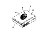
図1は本発明の一実施の形態に係るノートパソコンを示す斜視図、図2は同実施の形態に係るノートパソコンを示す断面図、図3は同実施の形態に係る本体筐体及び蓋体筐体を示す断面図である。 1 is a perspective view showing a notebook computer according to an embodiment of the present invention, FIG. 2 is a cross-sectional view showing the notebook computer according to the embodiment, and FIG. 3 is a main body casing and a lid body according to the embodiment. It is sectional drawing which shows a housing | casing.
図1と図2に示すように、このノートパソコンPは、机上等に載置される本体10と、本体10に対して起伏可能に取付けられた蓋体20とから構成される。
As shown in FIGS. 1 and 2, the notebook computer P includes a
本体10は本体筐体11を有しており、その内部にはメモリ、CPU、ハードディスク等の電子部品12が収納され、上面にはキーボード13が設けられている。一方、蓋体20は蓋体筐体21を有しており、蓋体20が本体10側に倒されたときに本体10の上面と対向する前面には表示パネル22が設けられている。
The
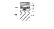
図3に示すように、本体筐体11及び蓋体筐体21は、生地となる樹脂製または金属製の筐体本体30と、筐体本体30の表面に形成される着色用のシルバーメタリック塗料膜31と、シルバーメタリック塗料膜31の表面に形成され、シルバーメタリック塗料膜31を保護する油性の第1のクリアー塗料膜32とから構成されている。
As shown in FIG. 3, the
シルバーメタリック塗料膜31及び第1のクリアー塗料膜32の厚さは、特に限定されるものではないが、本実施の形態ではシルバーメタリック塗料膜31の厚さを約15[μm]とし、第1のクリアー塗料膜32の厚さを10[μm]としている。
The thicknesses of the silver
このように通常のノートパソコンPは、本体筐体11及び蓋体筐体21の表面をシルバーメタリック塗料膜31等で着色し、その表面を透明な第1のクリアー塗料膜32で保護した状態で市販されている。
As described above, the normal notebook personal computer P is commercially available with the surfaces of the
ところで、本実施の形態に係るノートパソコンPでは、本体筐体11及び蓋体筐体21の所望部分に装飾用または識別用の絵柄がインクジェット式のプリンターによりフルカラーで印刷される。しかしながら、インクジェット式のプリンターで使用されるインクは水性であるため、本体筐体11及び蓋体筐体21に形成された油性の第1のクリアー塗料膜32上には水性のインクがうまく馴染まない。
By the way, in the notebook personal computer P according to the present embodiment, a decorative or identifying pattern is printed in full color on a desired portion of the
そこで、ノートパソコンPの本体筐体11及び蓋体筐体21における、絵柄を印刷する領域(以下、「印刷領域T」と称する。)、本実施の形態ではノートパソコンPの蓋体筐体21の背面に、筐体側からプライマー塗料膜40、水性のアンダー塗料膜41を順に形成し、その上に絵柄部分となる水性の印刷インク膜42、印刷インク膜42を保護する第2のクリアー塗料膜43を順に形成している。
Therefore, an area for printing a pattern (hereinafter referred to as “printing area T”) in the
すなわち、プライマー塗料膜40とアンダー塗料膜41により、油性の第1のクリアー塗料膜32と水性の印刷インク膜42とを馴染ませるための媒介膜44を構成している。
That is, the
このようにすれば、ノートパソコンPの本体筐体11及び蓋体筐体21の絵柄を印刷する印刷領域Tには、その前段階で水性のアンダー塗料膜41が形成されているから、印刷インク膜42をしっかりと馴染ませることができる。
In this way, since the water-based
なお、プライマー塗料膜40は、油性の第1のクリアー塗料膜32上に水性のアンダー塗料膜41を密着させるためのカップリング材である。また、プライマー塗料膜40、アンダー塗料膜41、第2のクリアー塗料膜43は、スプレー塗装により形成されている。
The
プライマー塗料膜40、アンダー塗料膜41、及び第2のクリアー塗料膜43の厚さは、特に限定されるものではないが、本実施の形態ではプライマー塗料膜40の厚さを約15[μm]とし、アンダー塗料膜41の厚さを約15[μm]とし、第2のクリアー塗料膜43の厚さを約15[μm]としている。
The thicknesses of the
また、本実施の形態では、筐体本体30の表面にシルバーメタリック塗料膜31と第1のクリアー塗料膜32を形成しているが、これに限定されるものではなく、例えばシルバーメタリック塗料膜31と第1のクリアー塗料膜32の代わりに、油性のUV塗料膜などを用いてもよい。
In the present embodiment, the silver
さらに、第1のクリアー塗料膜32を形成しなくてもよいし、シルバーメタリック塗料膜31と第1のクリアー塗料膜32の両方を形成しなくてもよい。これらの場合も、シルバーメタリック塗料膜31や第1のクリアー塗料膜32が油性であるため、プライマー塗料膜40とアンダー塗料膜41は形成する必要がある。
Furthermore, the first
次に、上記構成のノートパソコンPに絵柄を転写する転写装置50の構成を説明する。
Next, the configuration of the
図4は同実施の形態に係るノートパソコンPに絵柄を転写する転写装置50の構成を示す概略図である。
FIG. 4 is a schematic diagram showing a configuration of a
図4に示すように、この転写装置50は、塗装装置51(塗装手段)、スキャナー52(画像取込手段)、プリンター53(画像形成手段)、制御装置54、及び入力装置55を有している。
As shown in FIG. 4, the
塗装装置51はスプレー式であり、ノートパソコンPの印刷領域Tにプライマー塗料膜40、アンダー塗料膜41、及び第2のクリアー塗料膜43等を形成するものである。
The
スキャナー52は、写真や絵などの素材Sの画像を取り込んで画像データを生成するものである。
The
プリンター53はインクジェット式であり、スキャナー52により生成された画像データに基づいて、ノートパソコンPの印刷領域Tに素材Sの画像を印刷するものである。なお、このプリンター53では水性のインクが使用される。
The
制御装置54は、塗装装置51、スキャナー52、及びプリンター53に接続されており、これらを駆動制御するものである。
The control device 54 is connected to the
入力装置55は制御装置54に接続されており、膜40、41、43の厚さ、ノートパソコンP上における印刷領域Tの位置、画像の色濃淡、及びスキャナー52の解像度等を入力するものである。
The input device 55 is connected to the control device 54, and inputs the thickness of the
次に、上記構成のノートパソコンPに画像を転写するサービスの一例を説明する。なお、このサービスを行うためには、予め店舗に転写装置50を設置しておく必要がある。
Next, an example of a service for transferring an image to the notebook personal computer P having the above configuration will be described. In order to perform this service, it is necessary to install the
最初に、来店した客からノートパソコンP及び写真等の素材Sを受け取るとともに、ノートパソコンPの本体筐体11及び蓋体筐体21うちの画像を転写したい部分、すなわち印刷領域Tを聞く(受注工程)。そして、これらの情報を入力装置55から入力し、スキャナー52で素材Sの画像を取り込む(画像取込工程)。 First, the notebook PC P and the material S such as a photograph are received from a customer who visits the store, and the portion of the notebook PC P in which the image is to be transferred, that is, the printing area T is heard (order received). Process). Then, these pieces of information are input from the input device 55, and the image of the material S is captured by the scanner 52 (image capture process).
次に、塗装装置51により蓋体筐体21の印刷領域Tにプライマー塗料膜40とアンダー塗料膜41を順に形成し、その後、プリンター53により蓋体筐体21の印刷領域Tに素材Sの画像を印刷する(印刷工程)。これにより、蓋体筐体21の印刷領域Tには、客が持参した素材Sに対応したフルカラーの印刷インク膜42が形成される。
Next, the
次に、塗装装置51により印刷インク膜42の表面に第2のクリアー塗料膜43を形成し、第2のクリアー塗料膜43を乾燥させた後、ノートパソコンPを客に引き渡す(引渡工程)。以上でノートパソコンPに対する画像転写サービスが終了する。
Next, after the second
なお、本実施の形態では、客が持参した写真などの素材SをノートパソコンPに転写しているが、多数の絵柄が載っているカタログを各店舗に置いておき、このカタログから印刷したい絵柄を選んでノートパソコンPに転写してもよい。また、デジカメ等で撮影した画像を印刷する場合、デジカメの記録媒体から直接プリンター53に画像データを入力してもよい。
In this embodiment, the material S such as a photograph brought by the customer is transferred to the notebook computer P. However, a catalog containing a large number of patterns is placed in each store, and the pattern to be printed from this catalog is stored. May be selected and transferred to the notebook computer P. Further, when printing an image taken with a digital camera or the like, the image data may be directly input to the
また、本実施の形態では、転写装置50を店舗に設置しているが、これに限定されるものではなく、例えば各店舗は受注だけを行い、実際の印刷は印刷工場で行うようにしてもよい。この場合、客はノートパソコンPをその場で受け取ることはできないが、転写装置50の設置個数が減ることになるから、本サービスの導入コストを低く抑えることができる。
Further, in the present embodiment, the
上記構成の膜形成方法及びこれを用いて製造された電気製品によれば、スプレー塗装によりプライマー塗料膜40、アンダー塗料膜41、及び第2のクリアー塗料膜43を形成している。そのため、上記各膜40、41、43の厚さを簡単に制御でき、また均一にすることができる。しかも、スプレー塗装は、いわゆる乾式の印刷方法であるため、湿式のディッピング法に比べて乾燥時間を短縮することができる。
According to the film forming method having the above-described configuration and the electric product manufactured using the film forming method, the
また、客が持参した写真など素材Sをスキャナー52で取り込み、取り込んだ画像をノートパソコンPの本体筐体11及び蓋体筐体21の所望の領域に転写している。そのため、写真などの素材Sさえあれば、好きな画像を転写することができるから、ユーザー独自のオリジナリティーをノートパソコンPに与えることができる。
Further, the material S such as a photograph brought by the customer is captured by the
しかも、インクジェット式のプリンター53を用いて印刷している。そのため、とても精彩な画像をノートパソコンPに印刷することができる。
In addition, printing is performed using an
また、本実施の形態では、ノートパソコンPの蓋体筐体21に画像を印刷する場合について述べたが、これに限定されるものではない。すなわち、本体筐体11の上面であってもよいし、蓋体筐体21の前面であってもよい。また、電気製品であれば、携帯電話、携帯ステレオ、テレビジョン、冷蔵庫、エアコン等であってもよい。
In the present embodiment, the case where an image is printed on the
また、本実施の形態では、ノートパソコンPに画像を印刷する印刷手段として、インクジェット式のプリンター53を用いているが、これに限定されるものではなく、例えばパッド印刷を用いてもよい。通常、パッド印刷では油性の溶剤系インクが使用されるため、筐体の表面にプライマー塗料膜とアンダー塗料膜を形成する必要はない。すなわち、第1のクリアー塗料膜の表面に直接印刷することができる。
In the present embodiment, the
また、上記実施の形態において画像を転写する手段は印刷手段に限定されるものではなく、画像形成手段であれば他の手段を用いても良い。 In the above embodiment, the means for transferring the image is not limited to the printing means, and any other means may be used as long as it is an image forming means.
なお、本発明は、上記実施形態そのままに限定されるものではなく、実施段階ではその要旨を逸脱しない範囲で構成要素を変形して具体化できる。また、上記実施形態に開示されている複数の構成要素の適宜な組み合せにより種々の発明を形成できる。例えば、実施形態に示される全構成要素から幾つかの構成要素を削除してもよい。さらに、異なる実施形態に亘る構成要素を適宜組み合せてもよい。 Note that the present invention is not limited to the above-described embodiment as it is, and can be embodied by modifying the constituent elements without departing from the scope of the invention in the implementation stage. Further, various inventions can be formed by appropriately combining a plurality of constituent elements disclosed in the embodiment. For example, some components may be deleted from all the components shown in the embodiment. Furthermore, you may combine suitably the component covering different embodiment.
P…ノートパソコン(電気製品)、11…本体筐体、21…蓋体筐体(筐体)、32…第1のクリアー塗料膜、40…プライマー塗料膜、41…アンダー塗料膜、43…第2のクリアー塗料膜、44…媒介膜、50…転写装置、51…塗装装置(塗装手段)、52…スキャナー(画像取込手段)、53…プリンター(画像形成手段)。 P: notebook computer (electrical product), 11: body casing, 21: lid casing (housing), 32: first clear coating film, 40: primer coating film, 41: under coating film, 43: first 2 clear paint film, 44 ... mediating film, 50 ... transfer device, 51 ... painting device (painting means), 52 ... scanner (image capturing means), 53 ... printer (image forming means).
Claims (7)
上記画像取込手段により取り込まれた画像を電器製品の筐体に形成する画像形成手段と、
を具備することを特徴とする転写装置。 Image capturing means for capturing an image;
Image forming means for forming an image captured by the image capturing means on a housing of an electrical appliance;
A transfer apparatus comprising:
上記油性の膜の表面に水性の表面を有する媒介膜を形成するスプレー式の塗装手段を具備することを特徴とする請求項3記載の転写装置。 The casing of the electrical product has an oily film on its surface,
4. The transfer apparatus according to claim 3, further comprising spray-type coating means for forming a mediating film having an aqueous surface on the surface of the oil-based film.
上記画像を取込んで画像データを生成する画像取込工程と、
上記画像データに基づいて上記電気製品の筐体に上記画像を形成する画像形成工程と、
上記画像が形成された電気製品を客に引き渡す引渡工程と、
を具備することを特徴とする電気製品の筐体に画像を転写する転写方法。 Ordering process to receive electrical products and images from customers;
An image capturing process for capturing the image and generating image data;
An image forming step of forming the image on a housing of the electrical product based on the image data;
A delivery process of delivering the electrical product on which the image is formed to the customer;
A transfer method for transferring an image to a housing of an electrical product.
Priority Applications (1)
| Application Number | Priority Date | Filing Date | Title |
|---|---|---|---|
| JP2004113539A JP2005296734A (en) | 2004-04-07 | 2004-04-07 | Film forming method, electric product manufactured using the same, transfer device and transfer method using the same |
Applications Claiming Priority (1)
| Application Number | Priority Date | Filing Date | Title |
|---|---|---|---|
| JP2004113539A JP2005296734A (en) | 2004-04-07 | 2004-04-07 | Film forming method, electric product manufactured using the same, transfer device and transfer method using the same |
Publications (1)
| Publication Number | Publication Date |
|---|---|
| JP2005296734A true JP2005296734A (en) | 2005-10-27 |
Family
ID=35328932
Family Applications (1)
| Application Number | Title | Priority Date | Filing Date |
|---|---|---|---|
| JP2004113539A Pending JP2005296734A (en) | 2004-04-07 | 2004-04-07 | Film forming method, electric product manufactured using the same, transfer device and transfer method using the same |
Country Status (1)
| Country | Link |
|---|---|
| JP (1) | JP2005296734A (en) |
Cited By (1)
| Publication number | Priority date | Publication date | Assignee | Title |
|---|---|---|---|---|
| CN109731748A (en) * | 2019-03-04 | 2019-05-10 | 无锡市兴恒嘉科技有限公司 | A kind of Automated electronic product surface spray coating process |
-
2004
- 2004-04-07 JP JP2004113539A patent/JP2005296734A/en active Pending
Cited By (1)
| Publication number | Priority date | Publication date | Assignee | Title |
|---|---|---|---|---|
| CN109731748A (en) * | 2019-03-04 | 2019-05-10 | 无锡市兴恒嘉科技有限公司 | A kind of Automated electronic product surface spray coating process |
Similar Documents
| Publication | Publication Date | Title |
|---|---|---|
| US7621442B2 (en) | Printing a subscription using a mobile device | |
| US7403796B2 (en) | Printing dating information using a mobile device | |
| US6178087B1 (en) | Multimedia apparatus using a portable computer | |
| US8081351B2 (en) | Mobile phone handset | |
| US7575172B2 (en) | Printing a greeting card using a mobile device | |
| US7817989B2 (en) | Method of performing an action using a printed medium | |
| US7918390B2 (en) | Printing educational material using a mobile device | |
| US20100134815A1 (en) | Printing a List on a Print Medium | |
| US7988042B2 (en) | Method for playing a request on a player device | |
| US7843595B2 (en) | Printing a calendar using a mobile device | |
| CN103748546B (en) | Graphic communication device | |
| JP2005296734A (en) | Film forming method, electric product manufactured using the same, transfer device and transfer method using the same | |
| US7774025B2 (en) | Printing content on a reverse side of a coded surface | |
| US20070171460A1 (en) | Photo duplexing method | |
| JP2007125837A (en) | Image forming apparatus and electronic apparatus | |
| JP2010124182A (en) | State recording apparatus | |
| JP2002056738A (en) | Cover member for push-button switch and member for push-button switch | |
| US7920896B2 (en) | Printing an almanac using a mobile device | |
| JP2003063049A (en) | Photographing apparatus, image print apparatus, photographing method and image print providing method | |
| Stephenson | Some trends in the development of inkjet paper and other digital printing technologies. | |
| Oliver | An advanced guide to digital photography | |
| JP2008210271A (en) | Method of manufacturing memory medium and information processing system | |
| KR20160066936A (en) | Mobile terminal and method for fabricating the same | |
| JP2001310544A (en) | Print method and print device of printed image data | |
| JP2008254407A (en) | Print supply system of ornamentation seal |