JP2005296694A - Fishes separation table - Google Patents
Fishes separation table Download PDFInfo
- Publication number
- JP2005296694A JP2005296694A JP2004097999A JP2004097999A JP2005296694A JP 2005296694 A JP2005296694 A JP 2005296694A JP 2004097999 A JP2004097999 A JP 2004097999A JP 2004097999 A JP2004097999 A JP 2004097999A JP 2005296694 A JP2005296694 A JP 2005296694A
- Authority
- JP
- Japan
- Prior art keywords
- fish
- plate
- bank
- outlet
- sorting
- Prior art date
- Legal status (The legal status is an assumption and is not a legal conclusion. Google has not performed a legal analysis and makes no representation as to the accuracy of the status listed.)
- Granted
Links
- 241000251468 Actinopterygii Species 0.000 title claims abstract description 69
- 235000019688 fish Nutrition 0.000 title abstract description 56
- 238000000926 separation method Methods 0.000 title abstract description 8
- 230000003014 reinforcing effect Effects 0.000 claims description 12
- 230000002093 peripheral effect Effects 0.000 claims description 4
- 230000004888 barrier function Effects 0.000 claims description 3
- 230000002265 prevention Effects 0.000 abstract 2
- 238000012423 maintenance Methods 0.000 description 3
- 230000002787 reinforcement Effects 0.000 description 3
- 241000972773 Aulopiformes Species 0.000 description 1
- 241000238366 Cephalopoda Species 0.000 description 1
- 241000555825 Clupeidae Species 0.000 description 1
- 241001149724 Cololabis adocetus Species 0.000 description 1
- 241000238557 Decapoda Species 0.000 description 1
- 241000276438 Gadus morhua Species 0.000 description 1
- 241000269821 Scombridae Species 0.000 description 1
- 230000001174 ascending effect Effects 0.000 description 1
- 235000019516 cod Nutrition 0.000 description 1
- 230000000694 effects Effects 0.000 description 1
- 230000005923 long-lasting effect Effects 0.000 description 1
- 235000020640 mackerel Nutrition 0.000 description 1
- 238000004519 manufacturing process Methods 0.000 description 1
- 230000000149 penetrating effect Effects 0.000 description 1
- 235000019515 salmon Nutrition 0.000 description 1
- 235000019512 sardine Nutrition 0.000 description 1
- 235000014102 seafood Nutrition 0.000 description 1
- 235000015170 shellfish Nutrition 0.000 description 1
- 241000894007 species Species 0.000 description 1
- 229920003002 synthetic resin Polymers 0.000 description 1
- 239000000057 synthetic resin Substances 0.000 description 1
- 239000002023 wood Substances 0.000 description 1
Images


Classifications
-
- Y—GENERAL TAGGING OF NEW TECHNOLOGICAL DEVELOPMENTS; GENERAL TAGGING OF CROSS-SECTIONAL TECHNOLOGIES SPANNING OVER SEVERAL SECTIONS OF THE IPC; TECHNICAL SUBJECTS COVERED BY FORMER USPC CROSS-REFERENCE ART COLLECTIONS [XRACs] AND DIGESTS
- Y02—TECHNOLOGIES OR APPLICATIONS FOR MITIGATION OR ADAPTATION AGAINST CLIMATE CHANGE
- Y02A—TECHNOLOGIES FOR ADAPTATION TO CLIMATE CHANGE
- Y02A40/00—Adaptation technologies in agriculture, forestry, livestock or agroalimentary production
- Y02A40/80—Adaptation technologies in agriculture, forestry, livestock or agroalimentary production in fisheries management
- Y02A40/81—Aquaculture, e.g. of fish
Landscapes
- Farming Of Fish And Shellfish (AREA)
- Sorting Of Articles (AREA)
Abstract
Description
この本発明は、漁船より岸壁や漁港に陸揚げされた魚介類を、数人で魚種別に、或は同種の魚介類を大きさ別に選別する際に用いる魚類選別台に関する。 The present invention relates to a fish sorting table used when several people sort fish and seafood landed on a quay or fishing port from a fishing boat into different types of fish or the same type of fish and shellfish according to size.
漁船による漁は、特定の魚種、例えばイカ、カニ、サンマ、イワシ、タラ、サケ、サバ、マグロ、タイ等の漁獲を目的に行われるが、目的以外の魚種も漁獲される。特に底引き網による漁では、多種類の魚種が漁獲される。大型漁船やトロール船にあっては、魚種の自動選別装置を備えるものもあるが、中小漁船にあっては、船内で人手により大まかに区分けしたり、漁港等に陸揚げした後に区分けしていた。
漁獲された多種類の魚種中に、珍味な魚や高級魚も含まれていることがあるし、同種魚であっても、大小があったり、傷がついていたりするので、これを人手で選別する必要があった。
Fishing by fishing boats is carried out for the purpose of catching specific fish species such as squid, crabs, saury, sardines, cod, salmon, mackerel, tuna, Thailand, etc. However, fish species other than those are also caught. In particular, many types of fish are caught by fishing with a bottom net. Some large fishing boats and trawlers are equipped with an automatic sorting device for fish species, but some small and medium fishing boats are roughly classified manually on board or after landing at a fishing port.
Many types of fish caught may include delicacy and high-quality fish, and even the same species may be large or small or scratched. There was a need to do.
魚種等の選別の多くは、陸揚げ場の岸壁や漁港において複数の空箱を準備し、例えば、第一空箱に大きい魚を、第二空箱に中くらいの魚を、第三空箱に小さい魚を区別して入れるか、競場の床面において大中小に区別していた。
また、漁港等の近くに木製の固定選別台を設置し、該選別台の上に漁獲した雑多な魚を載せ、これを数人の人手にて選別する場合もあった。
In some cases, a wooden fixed sorting table is installed near a fishing port, and miscellaneous fish caught on the sorting table are placed and sorted by several people.
しかしながら、自動選別装置は高価であるにも拘わらず、魚種選別ができず、しかも傷つきやすい問題点があった。陸揚げ漁港(岸壁)における選別は、少量の選別に適するも、大漁の選別には不適であった。また、木製固定選別台における選別は、陸揚げ漁港における選別より能率的であるも、陸揚げ位置が複数ある漁港にあっては、固定選別台を複数配置する必要があり、その固定選別台によって作業空間が占有される問題点があると共に、木製であるためささくれが生じ、ささくれにて魚や手指を傷つける問題点もあった。
そこで本発明は上記の事情に鑑みてなされたものであり、その目的は、選別作業の能率化と作業空間の有効利用、及び衛生面の向上を目指した魚類選別台を提供することにある。
However, although the automatic sorting apparatus is expensive, it has a problem that it cannot sort the fish species and is easily damaged. Sorting at the landing fishing port (quay) is suitable for sorting small quantities, but unsuitable for sorting large fishing. In addition, although sorting on a wooden fixed sorting table is more efficient than sorting at a landing fishing port, in a fishing port with multiple landing positions, it is necessary to place multiple fixed sorting tables. There is a problem that occupies, and because it is made of wood, there is a problem in that it hurts fish and fingers.
The present invention has been made in view of the above circumstances, and an object of the present invention is to provide a fish sorting table aimed at improving the efficiency of sorting work, effectively using the work space, and improving hygiene.
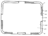
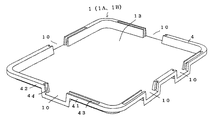
本発明の魚類選別台は、請求項1として、一定の広さを有する選別台板と、該台板を下から支える支持脚とを備え、選別台板は平板部の上側外周囲に魚類の流出を阻止する防魚堤を、下側に脚係止部を備え、防魚堤と平板部の少なくとも1箇所に魚類の取出口と、該取出口の開閉口手段とを備えている。
請求項2は、請求項1の魚類選別台において、取出口に対する開閉口手段は、防魚堤に軸支した遮蔽板の回動にて開閉する堤軸支式手段と、遮蔽板の摺動にて開閉するスライド式手段と、遮蔽板の嵌脱にて開閉する嵌脱式手段と、平板部に軸支した遮蔽板の回動にて開閉する平板軸支式手段との何れか一方である。
The fish sorting table according to the present invention includes, as claimed in
請求項3は、請求項2の魚類選別台において、堤軸支式手段は、取出口側堤部の一方に収納部を、他方に受け部を備え、収納部と受け部は上向きに、且つ取出口に向けて開口し、収納部内に遮蔽板基部を横軸にて支承する上下揺動式手段であり、遮蔽板を一方取出口側堤部側に回動した時、収納部内に挿入して取出口を開口し、他方取出口側堤部側に回動した時、遮蔽板先部が受け部に挿入して取出口を閉鎖している。
請求項4は、請求項1,2,3の魚類選別台において、選別台板は上側部材と下側部材とから成る二重構造式台板であり、上側部材は平板部の上側外周囲に防魚堤を備え、下側部材は上側部材を裏面から均等に支持する支持部と、上側部材の外周部に重なる固定部と、脚係止部とを備え、支持部と固定部とを上側部材に着接している。
請求項5は、請求項1,2,3,4の魚類選別台において、支持脚は脚壁の上側に台板載置部と、選別台板の脚係止部に係合する被係止部とを備え、脚壁は補強リブを設け、上下に積み重ねが可能となるように下向きに広く開口している。
According to a third aspect of the present invention, in the fish sorting table according to the second aspect, the bank support means includes a storage portion on one side of the outlet side bank portion and a receiving portion on the other side, and the storage portion and the receiving portion face upward. It is an up-and-down swing type means that opens toward the outlet and supports the shielding plate base on the horizontal axis in the storage portion. When the shielding plate is rotated to the side of the outlet side, it is inserted into the storage portion. When the outlet is opened and rotated to the other outlet side bank portion, the shielding plate tip is inserted into the receiving portion to close the outlet.
A fourth aspect of the present invention is the fish sorting table according to any one of the first, second, and third aspects, wherein the sorting plate is a double-structured base plate composed of an upper member and a lower member, and the upper member is disposed on the upper outer periphery of the flat plate portion. The lower member includes a supporting portion that uniformly supports the upper member from the back surface, a fixing portion that overlaps with the outer peripheral portion of the upper member, and a leg locking portion, and the supporting portion and the fixing portion are arranged on the upper side. It is attached to the member.
ここで選別台板とは、矩形状を成す平板部の上側外周囲に囲い部を設け、下側に脚係止部を有するものを言い、具体的には、上側部材の裏側に下側部材を着接した二重構造式台板と、上側部材の裏側に補強部材を着接した補強式台板とがあるが、一定量の魚類を溢れ出ないように収容するものであれば形状は自由である。
ここで上側部材とは、平板部の外周囲に防魚堤を設けるものを言い、下側部材とは、平板部を平滑に保つ支持部と、上側部材に着接する固定部とを備えるものを言う。
ここで脚係止部とは、選別台板の裏側二箇所に支持部と共に設けるもので、支持脚と嵌脱自在で、且つ嵌合状態において安定な凹部を言う。
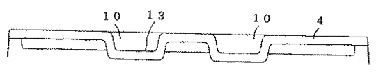
ここで取出口とは、防魚堤や平板部の任意切欠部を言い、その切欠部から外部への魚類の排出を滑らかにする所を言う。
Here, the sorting base plate refers to a rectangular plate having a surrounding portion provided on the upper outer periphery and having a leg locking portion on the lower side, specifically, a lower member on the back side of the upper member. There is a double structure type base plate attached to the upper side and a reinforcing type base plate attached to the back side of the upper member, but if it can accommodate a certain amount of fish so as not to overflow, the shape is Be free.
Here, the upper member refers to a member provided with a fish bank on the outer periphery of the flat plate portion, and the lower member includes a support portion that keeps the flat plate portion smooth and a fixing portion that contacts the upper member. say.
Here, the leg locking part is provided with the supporting part at two places on the back side of the sorting base plate, and refers to a concave part that can be fitted to and detached from the supporting leg and is stable in the fitted state.
Here, the “outlet” refers to an arbitrary cutout portion of a fish bank or a flat plate portion and a place where the discharge of fish from the cutout portion to the outside is smoothed.
ここで開閉口手段の堤軸支式手段とは、上下揺動可能に軸支する上下揺動式手段と、水平旋回可能に軸支する水平旋回式手段とを言い、スライド式手段とは、防魚堤から出し入れする左右スライド式手段と、平板部に対して昇降する上下スライド式手段とを言い、嵌脱式手段とは、上下嵌脱式手段と前後嵌脱式手段とを言い、平板軸支式手段とは、平板部の一部に軸支する堤開閉式手段と平板開閉式手段とを言うが、取出口を開閉し得るものであれば、その手段は自由である。
ここで支持脚とは、選別台板を下から支えるもので、二体一組で使用するものを言い、特に下向きに広く開口する空部を備え、周壁に補強リブを備えることにより軽量化を図り、且つ、積み重ねを可能することが望ましい。
又、支持脚の下側に、高さ調整手段(ジャッキー、滑り止めを兼ねた接地部)を備えておけば、選別者の背丈に応じて台高さを加減し得る。
ここで被係止部とは、選別台板の脚係止部と嵌脱自在で、且つ嵌合状態において安定な突部を言うが、上記目的を達するものであれば形状は自由である。
Here, the bank-supporting means of the opening and closing means means a vertically swinging means that is pivotally supported so as to be swingable up and down, and a horizontal swinging means that is pivotally supported so as to be horizontally swingable. Left and right sliding means to be taken in and out from the fish dam and up and down sliding means to be raised and lowered with respect to the flat plate portion, and the fitting and dismounting means means the upper and lower fitting means and the front and rear fitting means. The pivoting means means a bank opening / closing means and a plate opening / closing means pivotally supported on a part of the flat plate portion, and any means can be used as long as it can open and close the outlet.
Here, the support legs are those that support the sorting base plate from the bottom, and are used as a set of two bodies.In particular, the support legs are provided with a hollow portion that opens wide downward, and the peripheral walls are provided with reinforcing ribs to reduce the weight. It is desirable to be able to plan and stack.
Further, if a height adjusting means (a jacky and a grounding portion that also serves as an anti-slip) is provided on the lower side of the support leg, the height of the table can be adjusted according to the height of the sorter.
Here, the to-be-latched portion refers to a protruding portion that can be fitted to and detached from the leg locking portion of the sorting base plate and is stable in the fitted state. However, the shape is free as long as it achieves the above purpose.
本発明による魚類選別台は上記構造のとおりであるから、次に記載する効果を奏する。
請求項1の魚類選別台は、選別台板と、これを支える支持脚とから構成するものであるから、陸揚げに近い岸壁や漁港、或は競場等の適所に持ち運び、適所で組立て魚類を選別し得る。選別作業の終了後、分離してコンパクトに保管、又は格納しておける。このことにより、岸壁や漁港、或は競場等の作業空間を有効に使用できる。また、支持脚と選別台板との組立て分離は、工具等を用いずに簡単容易に、且つ安定状態で行える。
請求項2と請求項3の魚類選別台は、請求項1の特徴に加えて、開閉口手段として堤軸支式手段の内、遮蔽板基部を横軸にて支承する上下揺動式手段を採用しているので、遮蔽板を一方縦溝部側に回動するだけで取出口を開口し得るし、反対に他方縦溝部側に回動するだけで、取出口を閉鎖しえる。即ち、取出口の開閉が実に簡単容易である。
Since the fish sorting table according to the present invention has the above structure, the following effects can be obtained.
The fish sorting table according to
In addition to the features of
請求項4の魚類選別台は、請求項1,2,3の特徴に加えて、選別台板として、上側部材と下側部材とから成る二重構造式台板を採用しているので、負荷加重や耐久力が向上し、例え一度に大量の魚類を投入しても変形することがない。即ち、漁港等で荒っぽく使用しても、丈夫で長持ちする。しかも、製造も簡単容易になる。
請求項5の魚類選別台は、請求項1,2,3,4の特徴に加えて、支持脚の脚壁は下向きに広く開口しているので、上下に積み重ねておける。その結果、コンパクトに保管輸送し得る。しかも補強リブを備えているので、加重に対しても強い。
In addition to the features of
In addition to the features of the first, second, third and fourth aspects, the fish sorting table according to the fifth aspect can be stacked up and down because the leg walls of the support legs are wide open downward. As a result, it can be stored and transported in a compact manner. Moreover, since it has reinforcing ribs, it is strong against load.
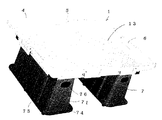
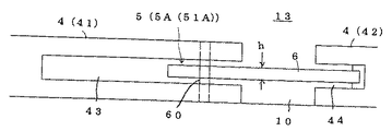
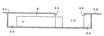
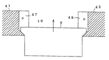
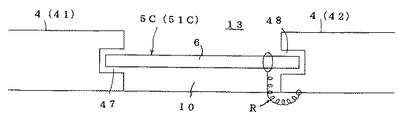
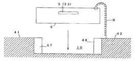
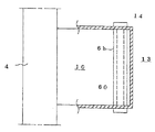
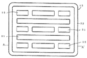
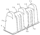
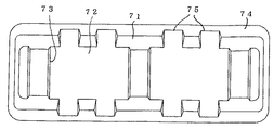
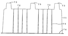
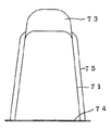
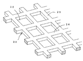
本発明による魚類選別台の最良形態を図1−1〜図1−4に基づき説明すれば、選別台板1と、該台板1を下から支える支持脚7とを備え、選別台板1は上側部材11と、上側部材11を裏面から均等に補強する下側部材12とから成る二重構造式台板1Aであり、その内、上側部材11は矩形状の平板部13の上側外周囲に魚類の流出を阻止する防魚堤4を備え、防魚堤4の任意個所に魚類の取出口10と、該取出口10の開閉口手段5とを備え、下側部材12は図9−1〜図9−3の如く、上側部材11の裏面に当設する支持部21と、上側部材11の外周部に重なる固定部22と、下向きに開口する脚係止部15とを設け、支持部21と固定部22とを上側部材11の裏面に着接して一体化するものであり、支持脚7は図10−1〜図10−4の如く、適宜高さを有する脚壁71の上側に台板載置部72と、脚係止部15に係合する被係止部73を、下側に接地部74を備え、且つ脚壁71に手掛け部76と、荷重方向に対する補強リブ75とを備え、積み重ねが可能となるように下向きに広く開口している。
The best mode of the fish sorting table according to the present invention will be described with reference to FIGS. 1-1 to 1-4. The
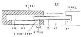
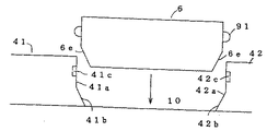
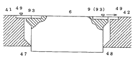
取出口10の開閉口手段5として、図1−5〜図1−7の如く防魚堤4に遮蔽板6を軸支持する堤軸支式手段5Aの内、防魚堤4の一方取出口側堤部41に遮蔽板6を上下揺動自在に軸支持する上下揺動式手段51Aを採用し、この上下揺動式手段51Aは、一方取出口側堤部41に遮蔽板長さHと遮蔽板厚さhより僅かに大きい収納部43を、他方取出口側堤部42に遮蔽板先部6aの受け部44を備え、収納部43と受け部44は共に上向きに、且つ取出口10に向けて開口し、収納部43に遮蔽板6の基部6bを挿入し、該基部6bと一方取出口側堤部41とに跨って横軸60を挿通し、横軸60を支点として上下揺動可能となるものである。
遮蔽板6を一方取出口側堤部41側に回動し、図1−5の如く収納部43に収まるまで深く回動することで取出口10が開口し、その遮蔽板6を他方取出口側堤部42側に向けて回動し、図1−6の如く遮蔽板先部6aが受け部44に収まることで取出口10が閉鎖する。
As the opening / closing means 5 of the take-
The
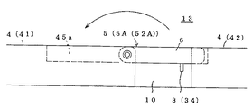
開閉口手段5の形態例を以下に説明すると、図2−1〜図2−3は、堤軸支式手段5Aの内、防魚堤4の一方取出口側堤部41に、遮蔽板6を縦軸50にて支承した水平旋回式手段52Aであり、この水平旋回式手段52Aは防魚堤4の取出口側堤部41,42の平板部13側に切欠部45a,46aを設け、その外側に薄肉部45b,46bを形成するものであり、切欠部45a,46aは天壁4a,4bを残して平板部13まで切欠し、一方の天壁4aと平板部13との間に遮蔽板基部6bを挿入し、これを縦軸50にて支承し、縦軸50を支点として水平旋回可能となるものであり、図2−2と図2−3の如く遮蔽板6を一方取出口側堤部41側に回動し、一方薄肉部45bに重ねることで取出口10は開口し、図2−1の如く遮蔽板6を他方取出口側堤部42側に回動し、遮蔽板先部6aを他方薄肉部46bに当接することで取出口10は閉鎖する。
An example of the form of the opening / closing means 5 will be described below. FIGS. 2-1 to 2-3 show that the shielding
図3−1〜図3−3は、遮蔽板6を摺動して開閉するスライド式手段5Bであり、その第一実施例の遮蔽板6を防魚堤4の長手方向に摺動する左右スライド式手段51Bである。
左右スライド式手段51Bを上下揺動式手段51Aと相違する点について説明すれば、一方取出口側堤部41に収納部43を、他方取出口側堤部42に受け部44を備え、遮蔽板6を収納部43に収まるまで摺動することで取出口10は開口し、他方取出口側堤部42に向け手摺動し、図3−1の如く受け部44に収まることで取出口10は閉鎖する。
FIGS. 3A to 3C are slidable means 5B for sliding the
The difference between the left / right sliding means 51B and the up / down swinging means 51A will be described. The
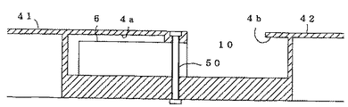
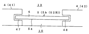
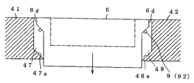
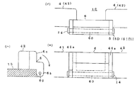
図4−1〜図4−3は、スライド式手段5Bの第二実施例で、遮蔽板6を取出口10に対して昇降する上下スライド式手段52Bである。
上下スライド式手段52Bを第一実施例と相違する点について説明すれば、取出口10に縦貫通長孔54を設け、取出口側堤部41,42に遮蔽板6の案内溝47,48を相対設し、案内溝47,48の下側に下降制限部47a,48aを設け、防魚堤高さSより僅かに長い遮蔽板6の上側に下降制限部47a,48aに当接する腕部6dを設け、上下動自在に嵌挿するものであり、図4−3の如く遮蔽板6の腕部6dが案内溝47,48の下降制限部47a,48aに当接するまで下降した時、遮蔽板6の上面が平板部13と面一となり、取出口10を開口し、図4−2の如く縦貫通長孔54より垂下した遮蔽板6の下側を押し上げ、所定の位置まで上昇した所で閉鎖維持手段9により降下を阻止し、取出口10は閉鎖する。
FIGS. 4-1 to 4-3 show a second embodiment of the sliding means 5B, which is a vertical sliding means 52B that lifts and lowers the shielding
Explaining the difference between the vertical sliding means 52B and the first embodiment, a longitudinal through hole 54 is provided in the
図5−1と図5−2は、遮蔽板6を嵌脱して開閉する嵌脱式手段5Cであり、その第一実施例の遮蔽板6を取出口10の上側から嵌脱する上下嵌脱式手段51Cである。
上下嵌脱式手段51Cを堤軸支式手段5A、及びスライド式手段5Bと相違する点について説明すれば、取出口側堤部41,42に案内溝47,48を相対設し、図5−2の如く遮蔽板6を案内溝47,48に添って降下挿入し、平板部13に当接するまで挿入することで取出口10は閉鎖し、その状態から遮蔽板6を案内溝47,48に添って上昇し、取外すことで取出口10は開口する。
この上下嵌脱式手段51Cにあっては、遮蔽板6を例えば一方取出口側堤部41に紐Rで取付けておくと紛失の恐れがないし、取出口10より取外した遮蔽板6を、例えば選別台板1の外側に垂下げておくことができる。
FIGS. 5A and 5B are fitting / removing means 5C for fitting / removing the shielding
If the vertical fitting / removing
In this vertical fitting / detaching means 51C, if the
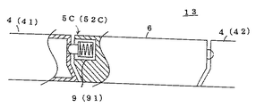
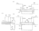
図6−1と図6−2は、嵌脱式手段5Cの第二実施例であり、且つ取出口10に対して前後方向より嵌脱する前後嵌脱式手段52Cである。
前後嵌脱式手段52Cを第一実施例と相違する点について説明すれば、取出口10を平板部13に向けて広口となるように形成し、取出口側堤部41,42の堤部端面41a,42aの少なくとも外寄り部に傾斜端面41b、42bを設け、遮蔽板6の両側面に堤部傾斜端面41b、42bに対応する被傾斜面6eを備え、
図6−1の如く取出口10の閉鎖時に、傾斜端面41b、42bと遮蔽板被傾斜面6eとが当接する。
FIGS. 6A and 6B are a second embodiment of the fitting / removing
The difference between the front / rear fitting / disengaging means 52C and the first embodiment will be described. The
As shown in FIG. 6A, when the
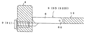
図7−1と図7−2は、開閉口手段5の内、遮蔽板6を平板部13の一部に軸支する平板軸支式手段5Dであり、その第一実施例の遮蔽板6を取出口10より外側の平板部13に軸支する堤開閉式手段51Dである。
堤開閉式手段51Dを説明すれば、水平旋回式手段52Aと反対に、取出口側堤部41,42の外部側に切欠部45a,46aを、平板部13側に薄肉部45b,46bを設け、取出口10より外側の平板部13に支承部14を備え、遮蔽板6は薄肉部45b,46bに当接する遮蔽部6cと、支承部14に横軸60で軸支する基部6bとを段違いに設け、横軸60を中心にして上下揺動可能となるものであり、図7−1の如く取出口10の閉鎖時に、遮蔽部6cは薄肉部45b,46bに当接し、図7−2の如く取出口10は開口時に、遮蔽部6cは取出口10より外側の下方に回動している。
FIGS. 7A and 7B are flat plate pivoting means 5D for pivotally supporting the
Explaining the bank opening and closing type means 51D, opposite to the horizontal turning type means 52A, notches 45a and 46a are provided on the outside of the outlet
図8−1〜図8−3は、平板軸支式手段5Dの第二実施例であり、防魚堤4より内側の平板部13に軸支する平板開閉式手段52Dである。
平板開閉式手段52Dを第一実施例と相違する点について説明すれば、平板部13の防魚堤4側に上下方向に貫通する平板取出口10を設け、該取出口10側の裏面に支承部14を備え、遮蔽板6は取出口10より一回り小さく、その基部6bを支承部14に横軸60で軸支し、横軸60を中心にして上下揺動可能となるものであり、図8−1の如く取出口10の閉鎖時に、遮蔽板6は平板部13と面一となるまで上向きに回動した所で閉鎖維持手段9により降下を阻止し、図8−2と図8−3の如く取出口10の開口時に、遮蔽板6は支承部14より下方に向けて垂下する。
FIGS. 8A to 8C show a second embodiment of the flat plate support means 5 </ b> D, which is a flat plate opening / closing means 52 </ b> D that supports the
The difference between the flat plate opening / closing means 52D and the first embodiment will be described. A
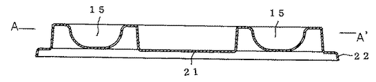
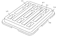
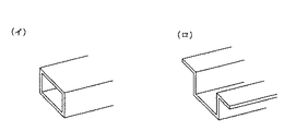
本発明による魚類選別台の実施例を、最良形態と相違する点について説明すると、選別台板1は上側部材11の裏面に補強部材20を着設する補強式台板1Bであり、補強式台板1Bの補強部材20は図11−1の如く縦桟部23と横桟部24とを適宜間隔で井桁状に連続し、縦桟部23と横桟部24との間に、下向きに開口する脚係止部15を形成するものである。
補強部材20を構成する縦桟部23と横桟部24は、角棒状や図11−2(イ)の如く角筒状を成し、その上面を上側部材11の裏面に着接して一体化するか、図11−2(ロ)の如くリップ溝型状を成し、リップを上側部材11の裏面に着接して一体化するものである。
An embodiment of the fish sorting table according to the present invention will be described in terms of differences from the best mode. The sorting table 1 is a reinforced table 1B in which a reinforcing
The
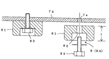
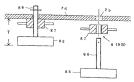
支持脚7の下側に高さ調整手段8を取付ければ、選別台板1の高さを使用現場に合わせて変更し得る。高さ調整手段8として、図14の如く嵩上げ式手段8Aと図15の如くジャッキー式手段8Bとを用いる。
その内、嵩上げ式手段8Aは接地体81に支持脚接地部74に設けた雌ねじ部7aに連通する貫通孔82を備え、接地体貫通孔82より接地部74の雌ねじ部7aに螺入する固定ボルト83にて固定するものであり、接地体厚さtを選択して固定することで、選別台板1の高さを可変するものである。
ジャッキー式手段8Bは、ねじ棒86を直立した接地体85と、ねじ棒86に螺合する手動ナット87とから成り、ねじ棒86を接地部74の抜き孔7bに相通し、選別台板1の自重によって手動ナット87に載置しており、手動ナット87の昇降にて可変高さTを調整するものである。
If the height adjusting means 8 is attached to the lower side of the
Among them, the raising type means 8A is provided with a through hole 82 communicating with the female screw portion 7a provided in the support
The jacky type means 8B includes a
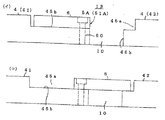
上下スライド式手段52Bにおける遮蔽板6の閉鎖維持手段9として、例えば図4−2の如く遮蔽板6の上昇状態において、遮蔽板6の腕部6dより下方の案内溝47,48にピン92を挿通するか、図13の如く遮蔽板6の上側に設けたスライド片93を取出口側堤部41,42に設けたガイド49までスライドするものである。(ガイド49とスライド片93とを反対に設けることも可能)
また、図6−1の如く前後嵌脱式手段52Cにおいて、遮蔽板6の両側面にノッチ91を設け、このノッチ91を堤部端面41a,42aの対抗面に設けた端面凹部41c,42cに係止する。(ノッチ91と凹部41c,42cとを反対に設けることも可能)
更に、平板開閉式手段52Dにおいて、例えば遮蔽板6の閉鎖回動時にノッチ91を後退し、閉鎖完了時にノッチ91が復帰して下降を阻止し、遮蔽板6の開口時に、ノッチ91を強制的に後退し、係止状態を開放することも可能である。
As the closing maintenance means 9 of the
Further, in the front and rear fitting means 52C as shown in FIG. 6A,
Further, in the flat plate opening / closing means 52D, for example, the
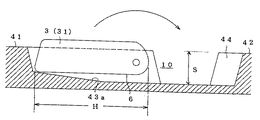
遮蔽板6に開閉操作を容易にする操作補助手段3を設けることが好ましい。例えば上下揺動式手段51Aにあっては、遮蔽板6の軸支位置を、遮蔽板6の中心より上側に偏心して軸支し、収納部43に上段部43aを備えておくことで、遮蔽板6の一部を収納部43より上側に露出する露出部31とし、この露出部31を把持して閉鎖回動し得るようにする。
左右スライド式手段51Bにあっては、図3−2と図3−3の如く、一方取出口側堤部41に収納部43から外部に連通する横貫通長孔53を備え、遮蔽板6の基部6bに、横貫通長孔53を貫通して外部に露出する把握部32を設け、この把握部32を把持してスライドする。
各開閉口手段5において、遮蔽板6の一部に窪み33を設け、この窪み32を利用して開閉することも可能であるし、遮蔽板6に摘み34を取付け、摘み34を把持して開閉することも可能である。
It is preferable to provide the
As shown in FIGS. 3-2 and 3-3, the left / right sliding means 51 </ b> B is provided with a lateral through
Each opening / closing means 5 can be provided with a
開閉口手段5は、堤軸支式手段5Aとスライド式手段5Bと嵌脱式手段5Cと平板軸支式手段5Dとに限定されるものではなく、取出口10を簡単に開閉し得るものであれば、その形態は自由である。
例えば、堤軸支式手段5Aの上下揺動式手段51Aにおいて、図12の如く一方取出口側堤部41の平板部13側に遮蔽板6を横軸60で片持ち支持し、横軸60を中心にして揺動することで、取出口10を開閉することも可能である。
選別台板1を構成する上側部材11と下側部材12、又は上側部材11と補強部材20、及び選別台板1を支える支持脚7は、合成樹脂製、特にFRPにて形成することが望ましい。
選別台板1の台板幅Lは200〜120cmが好ましいが、両側から作業できる範囲であれば自由であるし、取出口間隔Pは30〜100cmが好ましいが、隣の作業員とぶつからない範囲であれば自由である。
The opening / closing port means 5 is not limited to the bank support type means 5A, the slide type means 5B, the fitting / detaching type means 5C, and the flat plate support type means 5D, but can easily open and close the
For example, in the vertically swinging
The upper member 11 and the
Although the base plate width L of the sorting
1 選別台板、1A 二重構造式台板、1B 補強式台板
11 上側部材、12 下側部材、13 平板部、14 支承部、15 脚係止部
20 補強部材、21 支持部、22 固定部、23 縦桟部、24 横桟部
3 操作補助手段、31 露出部、32 把握部、33 窪み、34 摘み
4 防魚堤、4a,4b 天壁
41,42 取出口側堤部
41a,42a 堤部端面、41b,42b 傾斜端面、41c,42c 端面凹部
43 収納部、43a 段部、44 受け部
45a,46a 切欠部、45b,46b 薄肉部
47,48 案内溝、47a,48a 下降制限部、49 ガイド
5 開閉口手段
5A 堤軸支式手段、51A 上下揺動式手段、52A 水平旋回式手段
5B スライド式手段、51B 左右スライド式手段、52B 上下スライド式手段
5C 嵌脱式手段、51C 上下嵌脱式手段、52C 前後嵌脱式手段
5D 平板軸支式手段、51D 堤開閉式手段、52D 平板開閉式手段
53 横貫通長孔、54 縦貫通長孔
6 遮蔽板、6a 先部、6b 基部、6c 遮蔽部、6d 腕部、6e 被傾斜面
50 縦軸、60 横軸
7 支持脚、7a 雌ねじ部、7b 抜き孔
71 脚壁、72 台板載置部、73 被係止部、74 接地部、75 補強リブ
76 手掛け部
8 高さ調整手段、8A 嵩上げ式手段、8B ジャッキー式手段
81,85 接地体、82 貫通孔、83 固定ボルト、86 ねじ棒
87 手動ナット
9 閉鎖維持手段、91 ノッチ、92 ピン、93 スライド片
10 取出口
R 紐
H 遮蔽板長さ、h 遮蔽板厚さ
T 可変高さ、t 接地体厚さ
L 台板幅、P 取出口間隔
S 防魚堤高さ
DESCRIPTION OF SYMBOLS 1 Sorting base plate, 1A Double structure type base plate, 1B Reinforcement type base plate 11 Upper member, 12 Lower member, 13 Flat plate part, 14 Bearing part, 15 Leg locking part 20 Reinforcing member, 21 Support part, 22 Fixation , 23 Vertical beam portion, 24 Horizontal beam portion 3 Operation assisting means, 31 Exposed portion, 32 Grasping portion, 33 Dimple, 34 Pick 4 Fish breakwater, 4a, 4b Ceiling wall 41, 42 Take-out side bank portion 41a, 42a Dike end face, 41b, 42b Inclined end face, 41c, 42c End face recess 43 Storage part, 43a Step part, 44 Receiving part 45a, 46a Notch part, 45b, 46b Thin part 47, 48 Guide groove, 47a, 48a Lowering restriction part, 49 Guide 5 Opening / Closing Portion Means 5A Embankment-supporting means, 51A Vertical swinging means, 52A Horizontal turning means 5B Sliding means, 51B Left / right sliding means, 52B Vertical sliding means 5C Removable means 51C Vertical fitting / removal means, 52C Front / rear fitting / removal means 5D Flat shaft support type means, 51D Embankment opening / closing means, 52D Flat plate opening / closing means 53 Lateral long through hole, 54 Longitudinal through long hole 6 Shield plate, 6a Tip, 6b base part, 6c shielding part, 6d arm part, 6e inclined surface 50 vertical axis, 60 horizontal axis 7 support leg, 7a female thread part, 7b punch hole 71 leg wall, 72 base plate mounting part, 73 locked part, 74 Grounding part, 75 Reinforcement rib 76 Hand part 8 Height adjusting means, 8A Raising type means, 8B Jacky type means 81,85 Grounding body, 82 Through hole, 83 Fixing bolt, 86 Screw rod 87 Manual nut 9 Closure maintenance means, 91 Notch, 92 pin, 93 Slide piece 10 Takeout R String H Shield plate length, h Shield plate thickness T Variable height, t Grounding body thickness L Base plate width, P Takeout interval S Fish barrier height
Claims (5)
The support leg (7) has a base plate mounting portion (72) on the upper side of the leg wall (71), and a locked portion (73) that engages with the leg locking portion (15) of the sorting base plate (1). The fish according to claim 1, 2, 3 or 4, characterized in that the leg wall (71) is provided with reinforcing ribs (75) and is wide open downward so as to be able to be stacked up and down. Sorting table.
Priority Applications (1)
| Application Number | Priority Date | Filing Date | Title |
|---|---|---|---|
| JP2004097999A JP4826978B2 (en) | 2004-03-30 | 2004-03-30 | Fish sorting table |
Applications Claiming Priority (1)
| Application Number | Priority Date | Filing Date | Title |
|---|---|---|---|
| JP2004097999A JP4826978B2 (en) | 2004-03-30 | 2004-03-30 | Fish sorting table |
Publications (2)
| Publication Number | Publication Date |
|---|---|
| JP2005296694A true JP2005296694A (en) | 2005-10-27 |
| JP4826978B2 JP4826978B2 (en) | 2011-11-30 |
Family
ID=35328895
Family Applications (1)
| Application Number | Title | Priority Date | Filing Date |
|---|---|---|---|
| JP2004097999A Expired - Fee Related JP4826978B2 (en) | 2004-03-30 | 2004-03-30 | Fish sorting table |
Country Status (1)
| Country | Link |
|---|---|
| JP (1) | JP4826978B2 (en) |
Citations (6)
| Publication number | Priority date | Publication date | Assignee | Title |
|---|---|---|---|---|
| JPS51116849A (en) * | 1975-04-07 | 1976-10-14 | Du Pont Mitsui Fluorochem Co Ltd | Powdered copolymers from ethylene and fluorine containing olefin |
| JPH03231092A (en) * | 1990-02-02 | 1991-10-15 | Tatemi Sueshige | Fish sorting device in fishing boat |
| JPH03254619A (en) * | 1990-03-01 | 1991-11-13 | Aaru Pii Toupura Kk | Transportation container for live fish |
| JPH0793506A (en) * | 1992-12-11 | 1995-04-07 | Seibu Polymer Corp | Fish counter |
| JPH11165736A (en) * | 1997-12-03 | 1999-06-22 | Nippon Zanpakku Kk | Stacking container |
| JP2002086075A (en) * | 2000-09-14 | 2002-03-26 | Yutaka Sangyo Kikai Hanbai Kk | Fish selecting and living fish fainting apparatus |
-
2004
- 2004-03-30 JP JP2004097999A patent/JP4826978B2/en not_active Expired - Fee Related
Patent Citations (6)
| Publication number | Priority date | Publication date | Assignee | Title |
|---|---|---|---|---|
| JPS51116849A (en) * | 1975-04-07 | 1976-10-14 | Du Pont Mitsui Fluorochem Co Ltd | Powdered copolymers from ethylene and fluorine containing olefin |
| JPH03231092A (en) * | 1990-02-02 | 1991-10-15 | Tatemi Sueshige | Fish sorting device in fishing boat |
| JPH03254619A (en) * | 1990-03-01 | 1991-11-13 | Aaru Pii Toupura Kk | Transportation container for live fish |
| JPH0793506A (en) * | 1992-12-11 | 1995-04-07 | Seibu Polymer Corp | Fish counter |
| JPH11165736A (en) * | 1997-12-03 | 1999-06-22 | Nippon Zanpakku Kk | Stacking container |
| JP2002086075A (en) * | 2000-09-14 | 2002-03-26 | Yutaka Sangyo Kikai Hanbai Kk | Fish selecting and living fish fainting apparatus |
Also Published As
| Publication number | Publication date |
|---|---|
| JP4826978B2 (en) | 2011-11-30 |
Similar Documents
| Publication | Publication Date | Title |
|---|---|---|
| AU781095B2 (en) | Portable sink | |
| EP1596653B1 (en) | System for culture and storage of benthic organisms in an aquatic environment | |
| US2936066A (en) | Portable container for fishing tackle and other uses | |
| US2629644A (en) | Fishing tackle box | |
| US5054669A (en) | Portable lure container | |
| US3985409A (en) | Tackle box | |
| US5636469A (en) | Fishing tackle apparatus | |
| EP1849356A1 (en) | Foldable fish-trap | |
| US4488623A (en) | Canoe travel box | |
| US3867782A (en) | Crab trap | |
| US5975002A (en) | Storage system for marine craft | |
| US3889805A (en) | Fishing tackle rack | |
| US5593061A (en) | Fishing tackle storage and carrying apparatus | |
| AU662016B2 (en) | Multi-stage storage case for cassettes or cassette blocks | |
| US4621588A (en) | Shellfish cultivator | |
| US20240130571A1 (en) | Cutting board | |
| JP2005296694A (en) | Fishes separation table | |
| US2692007A (en) | Fisherman's chair | |
| US7040977B1 (en) | Fish cleaning system | |
| NO311961B1 (en) | Cultivation box for shells | |
| US4272904A (en) | Crab pot handling apparatus and method | |
| DE3436330C1 (en) | Apparatus for catching animals | |
| US20140165451A1 (en) | Hands-Free Bait Storage and Retrieval Apparatus | |
| KR200448531Y1 (en) | Fishing gear organizer | |
| CN109090842B (en) | Desk convenient to it is clean |
Legal Events
| Date | Code | Title | Description |
|---|---|---|---|
| A621 | Written request for application examination |
Free format text: JAPANESE INTERMEDIATE CODE: A621 Effective date: 20070306 |
|
| A977 | Report on retrieval |
Free format text: JAPANESE INTERMEDIATE CODE: A971007 Effective date: 20100318 |
|
| A131 | Notification of reasons for refusal |
Free format text: JAPANESE INTERMEDIATE CODE: A131 Effective date: 20100427 |
|
| A521 | Request for written amendment filed |
Free format text: JAPANESE INTERMEDIATE CODE: A523 Effective date: 20100622 |
|
| A131 | Notification of reasons for refusal |
Free format text: JAPANESE INTERMEDIATE CODE: A131 Effective date: 20110322 |
|
| A521 | Request for written amendment filed |
Free format text: JAPANESE INTERMEDIATE CODE: A523 Effective date: 20110513 |
|
| A131 | Notification of reasons for refusal |
Free format text: JAPANESE INTERMEDIATE CODE: A131 Effective date: 20110607 |
|
| A521 | Request for written amendment filed |
Free format text: JAPANESE INTERMEDIATE CODE: A523 Effective date: 20110715 |
|
| TRDD | Decision of grant or rejection written | ||
| A01 | Written decision to grant a patent or to grant a registration (utility model) |
Free format text: JAPANESE INTERMEDIATE CODE: A01 Effective date: 20110809 |
|
| A01 | Written decision to grant a patent or to grant a registration (utility model) |
Free format text: JAPANESE INTERMEDIATE CODE: A01 |
|
| A61 | First payment of annual fees (during grant procedure) |
Free format text: JAPANESE INTERMEDIATE CODE: A61 Effective date: 20110902 |
|
| FPAY | Renewal fee payment (event date is renewal date of database) |
Free format text: PAYMENT UNTIL: 20140922 Year of fee payment: 3 |
|
| R150 | Certificate of patent or registration of utility model |
Ref document number: 4826978 Country of ref document: JP Free format text: JAPANESE INTERMEDIATE CODE: R150 |
|
| R250 | Receipt of annual fees |
Free format text: JAPANESE INTERMEDIATE CODE: R250 |
|
| R250 | Receipt of annual fees |
Free format text: JAPANESE INTERMEDIATE CODE: R250 |
|
| R250 | Receipt of annual fees |
Free format text: JAPANESE INTERMEDIATE CODE: R250 |
|
| R250 | Receipt of annual fees |
Free format text: JAPANESE INTERMEDIATE CODE: R250 |
|
| R250 | Receipt of annual fees |
Free format text: JAPANESE INTERMEDIATE CODE: R250 |
|
| R250 | Receipt of annual fees |
Free format text: JAPANESE INTERMEDIATE CODE: R250 |
|
| R250 | Receipt of annual fees |
Free format text: JAPANESE INTERMEDIATE CODE: R250 |
|
| LAPS | Cancellation because of no payment of annual fees |