JP2005296676A - Distributor for movable body, ratchet set, and cylindrical body - Google Patents
Distributor for movable body, ratchet set, and cylindrical body Download PDFInfo
- Publication number
- JP2005296676A JP2005296676A JP2005185323A JP2005185323A JP2005296676A JP 2005296676 A JP2005296676 A JP 2005296676A JP 2005185323 A JP2005185323 A JP 2005185323A JP 2005185323 A JP2005185323 A JP 2005185323A JP 2005296676 A JP2005296676 A JP 2005296676A
- Authority
- JP
- Japan
- Prior art keywords
- cylindrical
- ratchet
- main body
- moving body
- rear end
- Prior art date
- Legal status (The legal status is an assumption and is not a legal conclusion. Google has not performed a legal analysis and makes no representation as to the accuracy of the status listed.)
- Granted
Links
- 239000002537 cosmetic Substances 0.000 description 18
- 239000007788 liquid Substances 0.000 description 17
- 238000001125 extrusion Methods 0.000 description 6
- 230000002093 peripheral effect Effects 0.000 description 4
- 230000000052 comparative effect Effects 0.000 description 3
- 238000000465 moulding Methods 0.000 description 3
- 238000005452 bending Methods 0.000 description 2
- 238000005336 cracking Methods 0.000 description 2
- 239000000463 material Substances 0.000 description 2
- 229910000831 Steel Inorganic materials 0.000 description 1
- 230000004308 accommodation Effects 0.000 description 1
- 239000011248 coating agent Substances 0.000 description 1
- 238000000576 coating method Methods 0.000 description 1
- 238000007599 discharging Methods 0.000 description 1
- 239000003814 drug Substances 0.000 description 1
- 239000011344 liquid material Substances 0.000 description 1
- 239000011343 solid material Substances 0.000 description 1
- 239000010959 steel Substances 0.000 description 1
- 229920003002 synthetic resin Polymers 0.000 description 1
- 239000000057 synthetic resin Substances 0.000 description 1
Images
Landscapes
- Containers And Packaging Bodies Having A Special Means To Remove Contents (AREA)
Abstract
Description
本発明は、例えば使用者が内蔵される液状化粧料を適宜押し出して使用するための液状化粧料押出容器などに用いられる移動体繰出装置、ラチェットセット、及び筒状体に関する。 The present invention relates to a moving body feeding device, a ratchet set, and a cylindrical body used for a liquid cosmetic extrusion container for appropriately extruding and using a liquid cosmetic contained by a user, for example.
従来の移動体繰出装置としては、例えば外周に雄螺子が形成されるとともに外側に開口し、かつ、長さ方向に延びる溝が周方向に沿って複数形成される筒状の移動体と、後側から挿入された移動体の雄螺子と螺合する雌螺子が内周の途中部分に形成される筒状の本体と、本体の後端部に回転可能に連結され、内周に移動体の溝と嵌り合う突条が軸体に設けられる筒状の操作体とを備え、移動体を回転不能かつ長さ方向に摺動自在に挿入し本体と操作体とを相対回転させることで移動体を順次繰り出すようにしたものが開示されている(例えば、特許文献1参照)。
ところで、近年、製品の携帯性や使い勝手を重視する消費者ニーズに伴い、従来の移動体繰出装置に対しては、移動体を繰り出す長さを変えずに装置全体の長さを短くすることで製品のコンパクト化を図ることが要請されている。 By the way, in recent years, along with consumer needs that place importance on the portability and usability of products, it is possible to shorten the overall length of the device without changing the length of the moving device for the conventional moving device. There is a demand for compact products.
そこで、本発明の課題は、製品のコンパクト化が十分に図られるように、従来のものに比して、同一繰出量を確保しつつ全長を短くできる移動体繰出装置、ラチェットセット、及び筒状体を提供することにある。 Therefore, the object of the present invention is to provide a movable body feeding device, a ratchet set, and a cylindrical shape that can shorten the overall length while ensuring the same feeding amount as compared with the conventional one so that the product can be made compact enough. To provide a body.
本発明に係る筒状体は、円筒部と、円筒部の内周に設けられた雌螺子と、円筒部の外周に一体に形成された鍔部と、鍔部の後端側に凹設された環状溝と、環状溝の底面に設けられたラチェット歯と、を備えることを特徴とする。 The cylindrical body according to the present invention is provided with a cylindrical portion, a female screw provided on the inner periphery of the cylindrical portion, a flange integrally formed on the outer periphery of the cylindrical portion, and a recess on the rear end side of the flange. An annular groove and ratchet teeth provided on the bottom surface of the annular groove.
また本発明に係るラチェットセットは、上記した筒状体と、筒状体のラチェット歯と噛合するラチェット歯及びラチェットバネを一体に成形してなる筒状のラチェットバネ部と、を備えることを特徴とする。 The ratchet set according to the present invention includes the above-described cylindrical body, and a cylindrical ratchet spring portion formed by integrally forming a ratchet tooth and a ratchet spring that mesh with the ratchet teeth of the cylindrical body. And
また本発明に係る移動体繰出装置は、筒状の本体と、本体の内周の途中部分において回転不能に配置される上記した筒状体と、外周に筒状体の雌螺子と螺合する雄螺子が形成される移動体と、本体の後端部に対して回転可能に連結され、雌螺子に螺合した移動体を回転不能かつ長さ方向に摺動自在に保持する筒状の操作体と、筒状体のラチェット歯と噛合するラチェット歯及びラチェットバネを一体に成形してなる筒状のラチェットバネ部と、を備え、ラチェットバネ部は、その内側を移動体が通過するように、筒状体と操作体の内部との間に挟み付けられており、本体と操作体とを相対回転させることで移動体が順次繰り出される、ことを特徴とする。 Further, the mobile body feeding device according to the present invention is screwed into the cylindrical main body, the above-described cylindrical body that is non-rotatably disposed in the middle of the inner periphery of the main body, and the female screw of the cylindrical body on the outer periphery. Cylindrical operation for holding a movable body in which a male screw is formed and a movable body that is rotatably connected to the rear end portion of the main body and that is screwed into the female screw and that is non-rotatable and slidable in the length direction. And a ratchet spring portion formed by integrally forming a ratchet tooth and a ratchet spring meshing with the ratchet teeth of the cylindrical body, and the ratchet spring portion so that the moving body passes inside Further, the movable body is sandwiched between the cylindrical body and the inside of the operating body, and the moving body is sequentially drawn out by relatively rotating the main body and the operating body.
なお、本発明において、雄螺子、雌螺子とは、これらと同様な働きをする螺子状の突起、溝を含む概念である。 In addition, in this invention, a male screw and a female screw are the concept containing the screw-shaped protrusion and groove | channel which function similarly to these.
本発明に係る移動体繰出装置、ラチェットセット、及び筒状体によれば、従来のものに比して、同一繰出量を確保しつつ全長を短くでき、製品のコンパクト化が十分に図られる。 According to the mobile body feeding device, the ratchet set, and the cylindrical body according to the present invention, the overall length can be shortened while ensuring the same feeding amount as compared with the conventional one, and the product can be sufficiently compact.
以下、添付図面に基づいて本発明の実施の形態を詳細に説明する。 Hereinafter, embodiments of the present invention will be described in detail with reference to the accompanying drawings.
なお、ここでは、移動体繰出装置がファンデーション、チークカラーや美容液等の液状化粧料を押し出すための液状化粧料押出容器に適用された場合について説明するが、これに限られるものではなく、例えば筆記用具のインクや液状医薬品等の液状材料のほか、固形材料である棒状化粧料を繰り出すための棒状化粧料繰出容器などに適用される場合でも、以下の説明が妥当する。 Here, the case where the moving body feeding device is applied to a liquid cosmetic extruding container for extruding liquid cosmetics such as foundation, cheek color and cosmetic liquid will be described, but the present invention is not limited to this. The following explanation is valid even when applied to a stick-shaped cosmetic material feeding container for feeding a stick-shaped cosmetic material as a solid material, in addition to liquid materials such as ink for writing instruments and liquid pharmaceuticals.
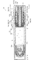
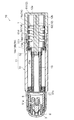
図1は本発明の一実施の形態に係る移動体繰出装置が適用された液状化粧料押出容器の全体構成を示す縦断面図(移動体の繰出前)、図2は同移動体繰出装置が適用された液状化粧料押出容器の全体構成を示す縦断面図(移動体の繰出後)である。 FIG. 1 is a longitudinal sectional view (before feeding of a moving body) showing the overall configuration of a liquid cosmetic extruding container to which a moving body feeding apparatus according to an embodiment of the present invention is applied, and FIG. 2 shows the moving body feeding apparatus. It is a longitudinal cross-sectional view (after delivery of a moving body) which shows the whole structure of the applied liquid cosmetics extrusion container.
本実施の形態において、液状化粧料押出容器10は、図1に示すように、移動体繰出装置1と、ピストン2と、吐出蓋3と、キャップ4とを備えている。また、この液状化粧料押出容器10は、図1及び図2に示すように、本体筒51内に画成されており、液状化粧料を収容するための液状化粧料収容領域5を有している。
In this Embodiment, the liquid
ここで、ピストン2は、円板形状を成しており、移動体13の先端部に一体的に接合され、本体筒51の内周面に水密に接触しながら軸線方向に摺動自在に挿嵌されている(図1及び図2参照)。
Here, the
また、吐出蓋3は、本体筒51の先端に装着されており、移動体13の移動に従ってピストン2により押し出される液状化粧料を本体筒51の先端から吐き出す役割を果たす(図1及び図2参照)。もちろん、これに限られるものではなく、本体筒51の先端に装着し得るものであれば、例えば刷毛なども用いることができる。
The
さらに、キャップ4は、本体筒51の先端筒部51aに着脱自在に装着されており、塗布体6等を覆う役割を果たす(図1参照)。
Further, the
そして、移動体繰出装置1は、図1及び図2に示すように、筒状の本体11と、筒状の操作体12と、筒状の移動体13と、ラチェット14とを備えている。
And the mobile
つまり、移動体繰出装置1は、本体11と操作体12とを相対回転させることで移動体13を順次繰り出す役割を果たすものとして構成されている。
That is, the mobile
以下、これらの各構成要素についてさらに詳細に説明する。 Hereinafter, each of these components will be described in more detail.
(1)本体11
(1)
本体11は、後側から挿入された移動体13の螺子部たる雄螺子13aと螺合する雌螺子11aが内周の途中部分に形成されており、本体11の内部には、途中部分の内周と途中部分以外の部分の内周との段差部たる鍔部11bが形成されている(図1及び図2参照)。
In the
具体的には、本体11は、図1及び図2に示すように、本体筒51と、筒状体52とからなっている。
Specifically, as shown in FIGS. 1 and 2, the
本体筒51は、円筒形状を成すものとして構成されている(図1及び図2参照)。
The
そして、この本体筒51は、図1に示すように、先端側に外径が小径とされる先端筒部51aを備え、後端側に内径が大径とされる後端筒部51bを備えている。
As shown in FIG. 1, the
この本体筒51の内周には、同図に示すように、先端から所定長の位置に環状凸部51cが形成されており、後端筒部51bの段部51d寄りの位置に、軸線方向に所定長延びる突条51eが円周方向に略等間隔で複数個形成されており、さらに、本体筒51後端面寄りの位置に環状凹部51fが形成されている。
As shown in the figure, an
一方、筒状体52は、図1に示すように、本体筒51の後端筒部51b内の段部51d寄りの位置に挿入配置されている。
On the other hand, as shown in FIG. 1, the
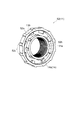
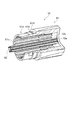
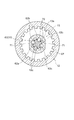
この筒状体52は、図3に示すように、円筒形状を成す円筒部52aと、この円筒部52a外周に一体に成形される段差部たる鍔部11bとを備えている。
As shown in FIG. 3, the
この円筒部52aの内周には、同図に示すように、軸線を中心として筒側の螺子部たる雌螺子11aが形成されている。また、同図に示すように、鍔部11bの後端側は、環状に凹設される環状溝52bとされており、この環状溝52bの底面に、後端側に向かうとともに一方の周方向に傾斜して突出するラチェット歯14aを円周方向に略等間隔で複数個備えている。また、同図に示すように、鍔部11bの外周には、軸線方向に延びる突条52cが円周方向に略等間隔で複数個形成されている。
As shown in the figure, a
そして、この筒状体52は、図1及び図2に示すように、これより後端側の後述するラチェットバネ部81により付勢されており、鍔部11bの先端側縁部が後端筒部51bの段部51dに当接するとともに、鍔部11bの各突条52cが本体筒51の内周に略長さ方向に複数形成される各突条51e間に位置することで本体筒51に対して回転不能に連結されている。
As shown in FIGS. 1 and 2, the
(2)操作体12
(2)
操作体12は、図1、図2及び図4に示すように、後端に底12aを有しており、本体11の後端部に対して雌螺子11aの有する軸線を中心として回転可能に連結されている。そして、この操作体12の内周の後側には、内周の前側より内側に突出した突出部たるバネ押え12bが周方向に沿って間欠的に設けられている。
As shown in FIGS. 1, 2, and 4, the
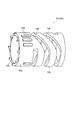
この操作体12は、こられの図に示すように、操作筒61と、軸体62とからなっている。
As shown in these drawings, the
操作筒61は、図4に示すように、円筒形状を成している。この操作筒61は、先端側に外径が小径とされる先端筒部61aを備えており、この先端筒部61aの外周に、環状凸部61bを備えている。また、この操作筒61は、同図に示すように、その内周に、先端側から軸線方向に所定長延びる突条61cを円周方向に略等間隔で複数個備えるとともに、この突条61cに連設されて底12aまで延在し突条61cより軸心側に突出するバネ押え12bを備えている。
As shown in FIG. 4, the
そして、この操作筒61は、図1、図2及び図4に示すように、先端筒部61aが本体筒51の後端筒部51b内に挿入されており、先端筒部61aの段部61dが本体筒51の後端面に当接して環状凸部61bが本体筒51の環状凹部51fに嵌入し、本体筒51と相対回転可能に連結されている。
As shown in FIGS. 1, 2, and 4, the
一方、軸体62は、図1及び図2に示すように、底12aから前側に突出して設けられており、後側から移動体13内に回転不能かつ長さ方向に摺動自在に挿入されている。
On the other hand, as shown in FIGS. 1 and 2, the
この軸体62は、図4及び図5に示すように、その底12a中央に先端側に向かうように立設されており、略十字状を成している。この軸体62は、部品点数の低減及び組立の容易性の観点から、操作筒61に一体に成形されているが、別体として嵌着や螺子込み等で連結しても良い。
As shown in FIGS. 4 and 5, the
すなわち、このような軸体62によれば、後側から移動体13内に挿入する構成によって操作体12による回転力を移動体13に伝えることが可能となっており、これにより、従来の移動体繰出装置に比して、同一繰出量を確保しつつ全長を短くすることが可能となっている。
That is, according to such a
ここで、図5に示すように、軸体62は、その外周に筒側の回り止め部を備えている。つまり、軸体62には、円周方向90°間隔の位置を断面凹状に窪む形状にすることで、断面凹状の凹部62cが複数(本実施形態では4個)形成されていると共に、この凹部62cの両側に、それぞれが外側に突出し、かつ、長さ方向に延びる突条62aが周方向に沿って複数(本実施形態では4個)形成されている。また、同図に示すように、移動体13は、その内周に移動体の回り止め部を備えている。つまり、移動体13の内周には、突条62aと嵌り合う複数の溝13bが形成されていると共に、この溝13bの両側に突条72が形成されている。そして、この移動体13の突条72の先端縁が、軸体62に支持される被支持部たる被支持縁13cとされている。
Here, as shown in FIG. 5, the
さらに、同図に示すように、軸体62の突条62aは、その先端側から途中部分迄が移動体13の溝13b内に進入すると共に、それ以上の進入を阻止し移動体13と軸体62との半径方向の相対位置を所定に維持するように(心ズレを防止するように)、突条62aの途中部分より基部側に亘っては、溝13bの大きさより多少大きい突条に構成されている。そして、この突条62aの途中部分の段差部が、移動体13の被支持縁13cを支持するための支持部たる支持縁62bとされている。なお、軸体62の突条62aの溝13b内へのそれ以上の進入を阻止する構成としては、本実施形態の階段状の段差部に限定されるものではなく、傾斜面等を備える突条であっても良く、また、鍔部等を備える突条であっても良く、要は、突条62aの途中部分が、溝13b内に進入しているそれより先端側の部分に比して大きく、さらに、溝13bの大きさより大きく構成されていれば良い。
Furthermore, as shown in the figure, the
ここで、軸体を断面円形に構成すると共に外周面の所定位置に突条を突設し、この突条を備える軸体と相似形で多少大きい穴及び溝を、移動体に設けることで、移動体と軸体との半径方向の相対位置を所定に維持するという比較例の構成が考えられるが、この比較例の構成では、軸体の突条以外の部分(軸心部)の肉厚と突条の肉厚との差が大きく、その結果、成形品の表面に肉ひけを生じ易く、この肉ひけを防止するには成形時間を長くすることが必要であり、加えて、不均等の肉厚による硬化度に従って、残留応力による捩れ、曲がり、割れ等の変形が生じ易くなる。 Here, the shaft body is configured to have a circular cross section, and a protrusion is provided at a predetermined position on the outer peripheral surface, and a slightly larger hole and groove similar to the shaft body including the protrusion are provided in the moving body, Although a configuration of a comparative example in which the relative position in the radial direction between the moving body and the shaft body is maintained at a predetermined level can be considered, in this configuration of the comparative example, the thickness of the portion other than the protrusions (axial center portion) of the shaft body There is a large difference between the thickness of the ridge and the thickness of the ridge, and as a result, the surface of the molded product tends to cause sink marks. To prevent this sink mark, it is necessary to lengthen the molding time. According to the degree of hardening due to the thickness of the steel, deformation such as twisting, bending, and cracking due to residual stress is likely to occur.
しかしながら、本実施形態では、複数箇所を断面凹状に窪ませることで形成する軸体62の突条62aの構成が、その先端側から途中部分迄が移動体13の溝13b内に進入し、途中部分から基部側が、溝13b内に進入している途中部分迄に比して大きくされているが突条を成す構成されているため、突条62aを含む軸体62の形状を、例えば断面十字状のように、軸心から突条を放射状に突出する構成に近づけることが可能とされており、上述した比較例に比して軸体62全体の肉厚の均等化が図られるようになっている。
However, in the present embodiment, the configuration of the
(3)移動体13
(3) Moving
移動体13は、図5に示すように、筒形状を成しており、外周に雄螺子13aが形成されるものとして構成されている。
As shown in FIG. 5, the moving
具体的には、移動体13は、同図に示すように、円筒体の全長に亘る外周面の対向する部位に形成した二平面部71と、二平面部71を除く円弧面に軸線方向に沿って形成した雄螺子13aとを有している。
Specifically, as shown in the figure, the
また、移動体13は、図5に示すように、後端側の内径が小径とされており、この後端の小径とされる内周に、軸線方向に延びる突条72を円周方向に略等間隔で複数個備えている。
Further, as shown in FIG. 5, the
この移動体13は、図1に示すように、雄螺子13aの先端部と筒状体52内周の雌螺子11aとが螺合するとともに、突条72,72間に略十字状を成す軸体62の突条62aが位置し軸体62に対して回転不能、かつ、軸線方向に摺動可能に係合され、この状態で、突条72の後端面が軸体62の基端部付近に位置する配置とされている。
As shown in FIG. 1, the
すなわち、同図に示すように、この状態で、軸体62、筒状体52の雌螺子11a及びラチェット歯14a,14bが、軸線に直交する同一面において重なる配置とされている。
That is, as shown in the figure, in this state, the
(4)ラチェット14
(4)
ラチェット14は、図3及び図6に示すように、一組のラチェット歯、つまり、筒状体52のラチェット歯14a,後記するラチェットバネ部81のラチェット歯14b及びラチェットバネ14cを有しており、移動体13の前方向又は後方向への移動を規制するために用いられている。
3 and 6, the
具体的には、ラチェット14は、こられの図に示すように、一組のラチェット歯14a,14bのいずれか一方及びラチェットバネ14cを一体に成形してなる筒状のラチェットバネ部81を有している。そして、図1及び図2に示すように、このラチェットバネ部81が、その内側を軸体62が貫くことで移動体13を通過させるようにして、段差部たる筒状体52の鍔部11bと突出部たる操作筒61のバネ押え12bの間に挟み付けられている。
Specifically, as shown in these drawings, the
すなわち、このようなラチェットバネ部81によれば、その内側を軸体62が貫くことで移動体13を通過させることが可能となっており、これにより、従来の移動体繰出装置に比して、同一繰出量を確保しつつ全長を短くすることが可能となっている。
That is, according to such a
もちろん、ラチェットバネ部81としては、これに限られるものではなく、その内側を軸体62が貫くことで移動体13を通過させるようにして、段差部たる筒状体52の鍔部11bと操作体12の内部の間に挟み付けられていればよい。すなわち、このラチェットバネ部81として、例えば筒状体52の鍔部11bと操作体12の底12aの間に挟み付けられているものなども用いることができる。
Of course, the
具体的には、このラチェットバネ部81は、図7に示すように、合成樹脂より形成されており、同図に示すように、円筒形状を成す円筒部14dと、この円筒部14d後端に連設され円筒形状を成すラチェットバネ14cとを備えている。
Specifically, the
円筒部14dは、同図に示すように、その先端面に、先端側に向かうとともにラチェット歯14aと噛合するように傾斜して突出するラチェット歯14bを円周方向に略等間隔で複数個備えている。また、同図に示すように、円筒部14dの外周には、軸線方向に所定長延びる突条14eが円周方向に略等間隔で複数個形成されている。また、同図に示すように、ラチェットバネ14cは、外周面に螺旋状に切り欠かれるスリット14fを備えており、このスリット14fによりラチェットバネ14cが伸縮して付勢力が生じるようになっている。
As shown in the figure, the
このラチェットバネ部81は、図1に示すように、ラチェットバネ14cが筒状体52の鍔部11bと操作筒61のバネ押え12bとの間で圧縮されて長さ方向に付勢力を生じ、ラチェット歯14a,14bが噛合する(ラチェット歯14a,14a間にラチェット歯14b,14bが位置する)とともに、筒状体52の鍔部11bの先端側縁部が本体筒51の後端筒部51bの段部dに当接し、この状態で、円筒部14dの各突条14eが操作筒61の各突条61c,61c間に位置し、操作筒61に対して回転不能に連結されている。
As shown in FIG. 1, the
上記したように、このような移動体繰出装置1においては、操作体12による回転力を筒状の移動体13内に回転不能かつ長さ方向に摺動自在に挿入した軸体62を介して移動体13に伝えることが可能となっており、しかも、ラチェットバネ部81の内側を軸体62が貫くことで移動体13を通過させることが可能となっており、さらに、軸体62が、移動体13の雄螺子13aに螺合する本体11の雌螺子11aを貫く構成となっている。
As described above, in such a moving
したがって、このような移動体繰出装置1によれば、筒側の回り止め部としての軸体62と筒側の螺子部としての本体11の雌螺子11aとが軸線に直交する同一面において重なると共に、筒側の回り止め部としての軸体62とラチェット歯14a,14bとが軸線に直交する同一面において重なるため、従来のものに比して、同一繰出量を確保しつつ全長を短くすることが可能となっており、ひいては製品のコンパクト化が十分に図られることになっている。
Therefore, according to the moving
さらに、移動体繰出装置1によれば、軸体62と雌螺子11aとラチェット歯14a,14bとが軸線に直交する同一面において重なるため、一層のコンパクト化が図られている。
Furthermore, according to the moving
さらに、移動体繰出装置1によれば、突条62aの先端側から途中部分迄が移動体13の溝13b内に進入すると共に、それ以上の進入を阻止し移動体13と軸体62との半径方向の相対位置を所定に維持するように、突条62aの途中部分(本実施形態では途中部分より基部側)が、溝13bの大きさより大きい突条に構成されているため、突条を必要以上に長くしなくて良く、無理な成形を回避できるようになっている。
Furthermore, according to the moving
加えて、このような移動体繰出装置1においては、複数箇所を断面凹状に凹ませることで軸体62の上記突条62aを形成しているため、突条62aを含む軸体62の形状を、軸心から突条を放射状に突出する構成に近づけることが可能とされており、軸体62全体の肉厚の均等化が図られるようになっている。
In addition, in the moving
その結果、成形時間を長くすることなく成形品の表面の肉ひけが防止されていると共に、均等な硬化度にされ、捩れ、曲がり、割れ等の変形が生じ難くされている。 As a result, shrinkage of the surface of the molded product can be prevented without lengthening the molding time, and the degree of hardening can be made uniform, and deformation such as twisting, bending, and cracking is difficult to occur.
1…移動体繰出装置、2…ピストン、3…吐出蓋、4…キャップ、5…液状化粧料収容領域、6…塗布体、10…液状化粧料押出容器、11…本体、11a…雌螺子、11b…鍔部、12…操作体、12a…底、12b…バネ押え、13…移動体、13a…雄螺子、13b…溝、13c…被支持縁、14…ラチェット、14a…ラチェット歯、14b…ラチェット歯、14c…ラチェットバネ、14d …円筒部、14e…突条、14f…スリット、51…本体筒、51a…先端筒部、51b…後端筒部、51c…環状凸部、51d…段部、51e…突条、51f…環状凹部、52…筒状体、52a…円筒部、52b…環状溝、52c…突条、61…操作筒、61a…先端筒部、61b…環状凸部、61c…突条、61d…段部、62…軸体、62a…突条、62b…支持縁、62c…凹部、71…二平面部、72…突条、81…ラチェットバネ部。
DESCRIPTION OF
Claims (3)
前記円筒部の内周に設けられた雌螺子と、
前記円筒部の外周に一体に形成された鍔部と、
前記鍔部の後端側に凹設された環状溝と、
前記環状溝の底面に設けられたラチェット歯と、
を備えることを特徴とする筒状体。 A cylindrical portion;
A female screw provided on the inner periphery of the cylindrical portion;
A flange part integrally formed on the outer periphery of the cylindrical part;
An annular groove recessed in the rear end side of the flange,
Ratchet teeth provided on the bottom surface of the annular groove;
A cylindrical body comprising:
前記筒状体の前記ラチェット歯と噛合するラチェット歯及びラチェットバネを一体に成形してなる筒状のラチェットバネ部と、
を備えることを特徴とするラチェットセット。 A cylindrical body according to claim 1;
A cylindrical ratchet spring portion formed integrally with a ratchet tooth and a ratchet spring meshing with the ratchet teeth of the cylindrical body;
A ratchet set comprising:
前記本体の内周の途中部分において回転不能に配置される請求項1に記載の筒状体と、
外周に前記筒状体の前記雌螺子と螺合する雄螺子が形成される移動体と、
前記本体の後端部に対して回転可能に連結され、前記雌螺子に螺合した前記移動体を回転不能かつ長さ方向に摺動自在に保持する筒状の操作体と、
前記筒状体の前記ラチェット歯と噛合するラチェット歯及びラチェットバネを一体に成形してなる筒状のラチェットバネ部と、を備え、
前記ラチェットバネ部は、その内側を前記移動体が通過するように、前記筒状体と前記操作体の内部との間に挟み付けられており、
前記本体と前記操作体とを相対回転させることで前記移動体が順次繰り出される、ことを特徴とする移動体繰出装置。
A tubular body,
The cylindrical body according to claim 1, which is disposed so as to be non-rotatable in an intermediate portion of the inner periphery of the main body,
A moving body having a male screw threadedly engaged with the female screw of the cylindrical body on an outer periphery;
A cylindrical operating body that is rotatably connected to the rear end of the main body and holds the movable body screwed into the female screw in a non-rotatable and slidable manner in the length direction;
A cylindrical ratchet spring portion formed integrally with a ratchet tooth and a ratchet spring meshing with the ratchet teeth of the cylindrical body,
The ratchet spring portion is sandwiched between the cylindrical body and the inside of the operation body so that the moving body passes through the inside thereof,
The moving body feeding device, wherein the moving body is sequentially fed by relatively rotating the main body and the operating body.
Priority Applications (1)
| Application Number | Priority Date | Filing Date | Title |
|---|---|---|---|
| JP2005185323A JP3764892B2 (en) | 2002-07-09 | 2005-06-24 | Mobile body feeding device, ratchet set, and cylindrical body |
Applications Claiming Priority (2)
| Application Number | Priority Date | Filing Date | Title |
|---|---|---|---|
| JP2002200309 | 2002-07-09 | ||
| JP2005185323A JP3764892B2 (en) | 2002-07-09 | 2005-06-24 | Mobile body feeding device, ratchet set, and cylindrical body |
Related Parent Applications (1)
| Application Number | Title | Priority Date | Filing Date |
|---|---|---|---|
| JP2003137803A Division JP3735100B2 (en) | 2002-07-09 | 2003-05-15 | Mobile body feeding device |
Publications (2)
| Publication Number | Publication Date |
|---|---|
| JP2005296676A true JP2005296676A (en) | 2005-10-27 |
| JP3764892B2 JP3764892B2 (en) | 2006-04-12 |
Family
ID=35328878
Family Applications (1)
| Application Number | Title | Priority Date | Filing Date |
|---|---|---|---|
| JP2005185323A Expired - Lifetime JP3764892B2 (en) | 2002-07-09 | 2005-06-24 | Mobile body feeding device, ratchet set, and cylindrical body |
Country Status (1)
| Country | Link |
|---|---|
| JP (1) | JP3764892B2 (en) |
Cited By (1)
| Publication number | Priority date | Publication date | Assignee | Title |
|---|---|---|---|---|
| US8297867B2 (en) | 2006-08-11 | 2012-10-30 | Shiseido Co., Ltd. | Container for viscous cosmetic |
Citations (5)
| Publication number | Priority date | Publication date | Assignee | Title |
|---|---|---|---|---|
| JPS5824537U (en) * | 1981-08-12 | 1983-02-16 | 三菱農機株式会社 | transmission drive wheel |
| JPS59151631A (en) * | 1983-02-15 | 1984-08-30 | Honda Motor Co Ltd | Power transmission system torsional vibration absorber for vehicle |
| JPS6357275U (en) * | 1986-10-03 | 1988-04-16 | ||
| JPH03112131U (en) * | 1990-03-01 | 1991-11-15 | ||
| JPH0621515U (en) * | 1992-04-28 | 1994-03-22 | 株式会社ヒダン | Stick cosmetic container |
-
2005
- 2005-06-24 JP JP2005185323A patent/JP3764892B2/en not_active Expired - Lifetime
Patent Citations (5)
| Publication number | Priority date | Publication date | Assignee | Title |
|---|---|---|---|---|
| JPS5824537U (en) * | 1981-08-12 | 1983-02-16 | 三菱農機株式会社 | transmission drive wheel |
| JPS59151631A (en) * | 1983-02-15 | 1984-08-30 | Honda Motor Co Ltd | Power transmission system torsional vibration absorber for vehicle |
| JPS6357275U (en) * | 1986-10-03 | 1988-04-16 | ||
| JPH03112131U (en) * | 1990-03-01 | 1991-11-15 | ||
| JPH0621515U (en) * | 1992-04-28 | 1994-03-22 | 株式会社ヒダン | Stick cosmetic container |
Cited By (1)
| Publication number | Priority date | Publication date | Assignee | Title |
|---|---|---|---|---|
| US8297867B2 (en) | 2006-08-11 | 2012-10-30 | Shiseido Co., Ltd. | Container for viscous cosmetic |
Also Published As
| Publication number | Publication date |
|---|---|
| JP3764892B2 (en) | 2006-04-12 |
Similar Documents
| Publication | Publication Date | Title |
|---|---|---|
| JP3735100B2 (en) | Mobile body feeding device | |
| US7201526B2 (en) | Extruding container of applying filler | |
| JP6281103B2 (en) | Coating material extrusion container | |
| JP5108919B2 (en) | Filler extrusion container | |
| JP6188251B2 (en) | Feeding pencil | |
| JP6191970B2 (en) | Feeding pencil | |
| US7147396B2 (en) | Applying filler extruding container | |
| US6957753B2 (en) | Movable body feeding apparatus | |
| JP3965391B2 (en) | Stick-shaped cosmetics feeding container | |
| JP5393599B2 (en) | Coating material extrusion container | |
| WO2014192175A1 (en) | Cartridge-type cosmetic container | |
| JP4847791B2 (en) | Filler extrusion container | |
| JP3764892B2 (en) | Mobile body feeding device, ratchet set, and cylindrical body | |
| JP4740173B2 (en) | Coating material extrusion container | |
| US11641926B2 (en) | Coating material, feeding container | |
| JP6561278B2 (en) | Coating material extrusion container | |
| JP4939334B2 (en) | Coating material extrusion container | |
| JP4739847B2 (en) | Filler extrusion container | |
| JP4627433B2 (en) | Mobile feeding container | |
| JP6001416B2 (en) | Feeding container | |
| EP1698251B1 (en) | Stick-form cosmetic material feeding container | |
| JP2009247427A (en) | Rotary type dispensing container | |
| JP2025056620A (en) | Drawing material container cartridge and drawing material container set | |
| JPH0928457A (en) | Makeup core pay-out container | |
| JP2021132909A (en) | Cosmetic container |
Legal Events
| Date | Code | Title | Description |
|---|---|---|---|
| A975 | Report on accelerated examination |
Free format text: JAPANESE INTERMEDIATE CODE: A971005 Effective date: 20050808 |
|
| A131 | Notification of reasons for refusal |
Free format text: JAPANESE INTERMEDIATE CODE: A131 Effective date: 20051004 |
|
| A521 | Request for written amendment filed |
Free format text: JAPANESE INTERMEDIATE CODE: A523 Effective date: 20051201 |
|
| TRDD | Decision of grant or rejection written | ||
| A01 | Written decision to grant a patent or to grant a registration (utility model) |
Free format text: JAPANESE INTERMEDIATE CODE: A01 Effective date: 20060117 |
|
| A61 | First payment of annual fees (during grant procedure) |
Free format text: JAPANESE INTERMEDIATE CODE: A61 Effective date: 20060123 |
|
| R150 | Certificate of patent or registration of utility model |
Free format text: JAPANESE INTERMEDIATE CODE: R150 Ref document number: 3764892 Country of ref document: JP Free format text: JAPANESE INTERMEDIATE CODE: R150 |
|
| FPAY | Renewal fee payment (event date is renewal date of database) |
Free format text: PAYMENT UNTIL: 20100127 Year of fee payment: 4 |
|
| R250 | Receipt of annual fees |
Free format text: JAPANESE INTERMEDIATE CODE: R250 |
|
| FPAY | Renewal fee payment (event date is renewal date of database) |
Free format text: PAYMENT UNTIL: 20100127 Year of fee payment: 4 |
|
| FPAY | Renewal fee payment (event date is renewal date of database) |
Free format text: PAYMENT UNTIL: 20100127 Year of fee payment: 4 |
|
| FPAY | Renewal fee payment (event date is renewal date of database) |
Free format text: PAYMENT UNTIL: 20110127 Year of fee payment: 5 |
|
| R250 | Receipt of annual fees |
Free format text: JAPANESE INTERMEDIATE CODE: R250 |
|
| FPAY | Renewal fee payment (event date is renewal date of database) |
Free format text: PAYMENT UNTIL: 20110127 Year of fee payment: 5 |
|
| FPAY | Renewal fee payment (event date is renewal date of database) |
Free format text: PAYMENT UNTIL: 20120127 Year of fee payment: 6 |
|
| R250 | Receipt of annual fees |
Free format text: JAPANESE INTERMEDIATE CODE: R250 |
|
| FPAY | Renewal fee payment (event date is renewal date of database) |
Free format text: PAYMENT UNTIL: 20120127 Year of fee payment: 6 |
|
| FPAY | Renewal fee payment (event date is renewal date of database) |
Free format text: PAYMENT UNTIL: 20130127 Year of fee payment: 7 |
|
| R250 | Receipt of annual fees |
Free format text: JAPANESE INTERMEDIATE CODE: R250 |
|
| FPAY | Renewal fee payment (event date is renewal date of database) |
Free format text: PAYMENT UNTIL: 20130127 Year of fee payment: 7 |
|
| FPAY | Renewal fee payment (event date is renewal date of database) |
Free format text: PAYMENT UNTIL: 20130127 Year of fee payment: 7 |
|
| R250 | Receipt of annual fees |
Free format text: JAPANESE INTERMEDIATE CODE: R250 |
|
| R250 | Receipt of annual fees |
Free format text: JAPANESE INTERMEDIATE CODE: R250 |
|
| R250 | Receipt of annual fees |
Free format text: JAPANESE INTERMEDIATE CODE: R250 |
|
| R250 | Receipt of annual fees |
Free format text: JAPANESE INTERMEDIATE CODE: R250 |
|
| R250 | Receipt of annual fees |
Free format text: JAPANESE INTERMEDIATE CODE: R250 |
|
| R250 | Receipt of annual fees |
Free format text: JAPANESE INTERMEDIATE CODE: R250 |
|
| R250 | Receipt of annual fees |
Free format text: JAPANESE INTERMEDIATE CODE: R250 |
|
| R250 | Receipt of annual fees |
Free format text: JAPANESE INTERMEDIATE CODE: R250 |
|
| R250 | Receipt of annual fees |
Free format text: JAPANESE INTERMEDIATE CODE: R250 |
|
| S802 | Written request for registration of partial abandonment of right |
Free format text: JAPANESE INTERMEDIATE CODE: R311802 |
|
| R350 | Written notification of registration of transfer |
Free format text: JAPANESE INTERMEDIATE CODE: R350 |
|
| R250 | Receipt of annual fees |
Free format text: JAPANESE INTERMEDIATE CODE: R250 |
|
| R250 | Receipt of annual fees |
Free format text: JAPANESE INTERMEDIATE CODE: R250 |
|
| EXPY | Cancellation because of completion of term |