JP2005296658A - Method and apparatus for detecting tissue structure - Google Patents
Method and apparatus for detecting tissue structure Download PDFInfo
- Publication number
- JP2005296658A JP2005296658A JP2005111671A JP2005111671A JP2005296658A JP 2005296658 A JP2005296658 A JP 2005296658A JP 2005111671 A JP2005111671 A JP 2005111671A JP 2005111671 A JP2005111671 A JP 2005111671A JP 2005296658 A JP2005296658 A JP 2005296658A
- Authority
- JP
- Japan
- Prior art keywords
- contour
- data set
- anatomy
- boundary
- points
- Prior art date
- Legal status (The legal status is an assumption and is not a legal conclusion. Google has not performed a legal analysis and makes no representation as to the accuracy of the status listed.)
- Pending
Links
Images

Classifications
-
- A—HUMAN NECESSITIES
- A61—MEDICAL OR VETERINARY SCIENCE; HYGIENE
- A61B—DIAGNOSIS; SURGERY; IDENTIFICATION
- A61B8/00—Diagnosis using ultrasonic, sonic or infrasonic waves
- A61B8/08—Clinical applications
-
- G—PHYSICS
- G06—COMPUTING OR CALCULATING; COUNTING
- G06T—IMAGE DATA PROCESSING OR GENERATION, IN GENERAL
- G06T7/00—Image analysis
- G06T7/10—Segmentation; Edge detection
- G06T7/12—Edge-based segmentation
-
- A—HUMAN NECESSITIES
- A61—MEDICAL OR VETERINARY SCIENCE; HYGIENE
- A61B—DIAGNOSIS; SURGERY; IDENTIFICATION
- A61B6/00—Apparatus or devices for radiation diagnosis; Apparatus or devices for radiation diagnosis combined with radiation therapy equipment
- A61B6/50—Apparatus or devices for radiation diagnosis; Apparatus or devices for radiation diagnosis combined with radiation therapy equipment specially adapted for specific body parts; specially adapted for specific clinical applications
- A61B6/503—Apparatus or devices for radiation diagnosis; Apparatus or devices for radiation diagnosis combined with radiation therapy equipment specially adapted for specific body parts; specially adapted for specific clinical applications for diagnosis of the heart
-
- A—HUMAN NECESSITIES
- A61—MEDICAL OR VETERINARY SCIENCE; HYGIENE
- A61B—DIAGNOSIS; SURGERY; IDENTIFICATION
- A61B8/00—Diagnosis using ultrasonic, sonic or infrasonic waves
- A61B8/08—Clinical applications
- A61B8/0883—Clinical applications for diagnosis of the heart
-
- G—PHYSICS
- G06—COMPUTING OR CALCULATING; COUNTING
- G06T—IMAGE DATA PROCESSING OR GENERATION, IN GENERAL
- G06T2207/00—Indexing scheme for image analysis or image enhancement
- G06T2207/10—Image acquisition modality
- G06T2207/10132—Ultrasound image
-
- G—PHYSICS
- G06—COMPUTING OR CALCULATING; COUNTING
- G06T—IMAGE DATA PROCESSING OR GENERATION, IN GENERAL
- G06T2207/00—Indexing scheme for image analysis or image enhancement
- G06T2207/30—Subject of image; Context of image processing
- G06T2207/30004—Biomedical image processing
- G06T2207/30048—Heart; Cardiac
Landscapes
- Engineering & Computer Science (AREA)
- Health & Medical Sciences (AREA)
- Life Sciences & Earth Sciences (AREA)
- Physics & Mathematics (AREA)
- Surgery (AREA)
- Animal Behavior & Ethology (AREA)
- Radiology & Medical Imaging (AREA)
- Nuclear Medicine, Radiotherapy & Molecular Imaging (AREA)
- Biomedical Technology (AREA)
- Heart & Thoracic Surgery (AREA)
- Medical Informatics (AREA)
- Molecular Biology (AREA)
- Biophysics (AREA)
- Pathology (AREA)
- General Health & Medical Sciences (AREA)
- Public Health (AREA)
- Veterinary Medicine (AREA)
- Computer Vision & Pattern Recognition (AREA)
- General Physics & Mathematics (AREA)
- Theoretical Computer Science (AREA)
- Ultra Sonic Daignosis Equipment (AREA)
- Nuclear Medicine (AREA)
- Apparatus For Radiation Diagnosis (AREA)
- Magnetic Resonance Imaging Apparatus (AREA)
Abstract
【課題】診断データセットを処理して異なる型の組織同士間及び組織と血液の間の境界の位置を識別する。
【解決手段】生体組織構造に対応する診断画像を表すデータセットを得る工程と、そのデータセットの中で少なくとも1つの生体組織の象徴部を識別する工程と、データセットを輪郭テンプレートに重ねて、輪郭テンプレートを囲むデータセットの検索領域を走査して172〜180生体組織構造の所定の特徴を備えた境界を識別する工程を含む、医療診断画像データセットに基づいて生体組織構造を検出する。これにより、生体構造の所定の特徴に伴う境界点を識別する。
【選択図】図4A diagnostic data set is processed to identify the location of boundaries between different types of tissues and between tissues and blood.
A step of obtaining a data set representing a diagnostic image corresponding to a tissue structure; a step of identifying a symbolic part of at least one tissue in the data set; and overlaying the data set on a contour template; A tissue structure is detected based on the medical diagnostic image data set including scanning a search region of the data set surrounding the contour template to identify boundaries having predetermined features of the 172-180 tissue structure. Thereby, boundary points associated with predetermined features of the anatomy are identified.
[Selection] Figure 4
Description
本発明は、概ね医療診断装置に関する。特に、本発明は、診断データセットを取得処理して異なる型の組織同士間および組織と血液の間の境界の位置を識別する方法と装置に関する。 The present invention generally relates to medical diagnostic devices. In particular, the invention relates to a method and apparatus for acquiring diagnostic data sets to identify the location of boundaries between different types of tissues and between tissues and blood.
心臓画像データの処理は心臓がどのように機能しているかを判定するためには非常に興味深いものである。現在、多くの処理アルゴリズムはユーザが処理するデータを識別することに依存している。超音波では、患者と装置の限界により、ユーザは、心内膜または心外膜などのような希望の箇所を正確に識別できない。例えば、装置は、ユーザが正確な測定値を入力して組織の微細な可変外郭を追跡できるようにすることはできない。さらに、ユーザは測定を行う時間に制限を受けている。 Processing of cardiac image data is very interesting for determining how the heart is functioning. Currently, many processing algorithms rely on identifying data to be processed by the user. With ultrasound, due to patient and device limitations, the user cannot accurately identify the desired location, such as the endocardium or epicardium. For example, the device cannot allow a user to enter accurate measurements to track a fine variable outline of tissue. Furthermore, the user is limited in the time to perform the measurement.
例えば、左室機能の重要な測定値は、左室の拡張末期(ED)容積から収縮末期(ES)容積を引いた値をED容積で割った値として定義される駆出率(EF)である。今日、この測定値は1つまたは2つの面にEDとESの心内膜を手動で描くことによって推測されることが多い。これは、時間のかかる作業であるとともにモデルは、心室が直径に沿って対称であると仮定した上でのものである。また、多くの患者における画質の悪さから、容量を自動的に突き止めるのは困難である。 For example, an important measure of left ventricular function is the ejection fraction (EF) defined as the end ventricular end diastolic (ED) volume minus the end systolic (ES) volume divided by the ED volume. is there. Today, this measurement is often inferred by manually drawing the endocardium of ED and ES on one or two surfaces. This is a time consuming task and the model assumes that the ventricles are symmetric along the diameter. Also, it is difficult to automatically determine the capacity due to the poor image quality in many patients.
他の画像診断モダリティにおいても、心臓の画像を取得し、同じ問題を経験している。さらに、2つのタイプの組織の間の界面をより正確に識別できれば肝臓、動脈、嚢胞、腫瘍などのような他の生体組織または数多くの生体組織または物質においても役立つであろう。 Other diagnostic imaging modalities obtain the same image and experience the same problem. In addition, more accurate identification of the interface between the two types of tissues may also be useful in other biological tissues or many biological tissues or materials such as livers, arteries, cysts, tumors and the like.
よって、診断データセットを処理して体内の境界の位置を識別することによって上記および他のこれまで経験してきた問題に対処することができるような装置および方法が望まれる。 Thus, it would be desirable to have an apparatus and method that can address these and other previously experienced problems by processing diagnostic data sets to identify the location of boundaries within the body.
生体組織構造に対応する診断画像を表すデータセットを得る工程と、そのデータセットの中で少なくとも1つの生体組織の象徴部を識別する工程と、データセットを輪郭テンプレートに重ねて、輪郭テンプレートを囲むデータセットの検索領域を走査して生体組織構造の所定の特徴を備えた境界を識別する工程を含む、医療診断画像データセットに基づいて生体組織構造を検出するための方法を提供する。 Obtaining a data set representing a diagnostic image corresponding to the tissue structure; identifying a symbolic portion of at least one living tissue in the data set; and overlaying the data set on the contour template to surround the contour template A method is provided for detecting a tissue structure based on a medical diagnostic image data set comprising scanning a search region of the data set to identify a boundary with a predetermined characteristic of the tissue structure.
対象領域に超音波信号を伝達する送信機と、伝達された超音波信号からエコー信号を受信する受信機と、エコー信号を含む一連の画像フレームを保存するためのメモリとを備えた、心内膜を識別するために設けられた装置を提供する。一連の画像フレームは、少なくとも1心拍周期から構成される。また、この装置は、一連の画像フレームを処理して頂点と、一連の画像フレーム上の第1と第2の端部を有するAV面の少なくとも一方を識別し、頂点から第1と第2の端部をむすんだ輪郭テンプレートを一連の画像フレーム上に重ね、輪郭テンプレートに沿った点を識別し比較して心内膜の所定の特徴に基づいて境界を識別する信号処理部を含む。また、この装置は、信号処理部の出力に基づいて情報を出力するための出力部を備える。 Intracardiac comprising a transmitter for transmitting an ultrasonic signal to a target area, a receiver for receiving an echo signal from the transmitted ultrasonic signal, and a memory for storing a series of image frames including the echo signal An apparatus is provided for identifying a membrane. A series of image frames is composed of at least one heartbeat cycle. The apparatus also processes the sequence of image frames to identify a vertex and at least one of the AV planes having first and second ends on the sequence of image frames, and the first and second from the vertex. A signal processing unit is included that overlays the edged contour template on a series of image frames, identifies and compares points along the contour template, and identifies boundaries based on predetermined endocardial features. In addition, the apparatus includes an output unit for outputting information based on the output of the signal processing unit.
少なくとも2つの異なるタイプの組織を有する診断画像を表す一連のデータセットを得る工程と、その一連のデータセットの中から少なくとも2つの生体組織の象徴部を識別する工程と、少なくとも2つの生体組織の象徴部を輪郭テンプレートと接合する工程とを備えた、異なるタイプの組織間の輪郭を識別するための方法を提供する。また、この方法は、輪郭テンプレート上およびその周囲のデータポイントを識別する工程と、組織のある型から第2の型への変化を表す所定の特徴を有する境界を識別するためのデータポイントを比較する工程を備える。 Obtaining a set of data representing a diagnostic image having at least two different types of tissue, identifying a symbolic portion of at least two biological tissues from the set of data sets, and A method is provided for identifying contours between different types of tissue comprising the step of joining a symbolic portion with a contour template. The method also compares the data points on and around the contour template with the data points for identifying boundaries having predetermined characteristics that represent a change from one type of tissue to a second type. The process of carrying out is provided.
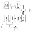
図1は、本発明の実施の形態により構成された超音波装置100のブロック図である。超音波装置100は、トランスデューサ106内に並んだエレメント104を駆動してパルス超音波信号を体に発信する送信機102を備える。配置は様々な相対位置が利用可能である。超音波信号は、血管細胞や筋肉細胞のように体の構造体から後方散乱され、エレメント104に戻るエコーを生成する。エコーは受信機108で受信する。受信したエコーは、ビームを形成してRF信号を出力するビーム形成器110を通過する。するとRF信号は、RFプロセッサ112を通過する。あるいは、RFプロセッサ112は、RF信号を復調してエコー信号を表すIQデータ対を形成する複合型復調装置(図示せず)を備えたものでもよい。そして、RFまたはIQ信号は直接RF/IQバッファ114に送られて一時的に保存される。
FIG. 1 is a block diagram of an
また、超音波装置100は、取得した超音波情報(例えば、RF信号データまたはIQデータ対)を処理して、表示装置118上に表示するための超音波情報のフレームを準備するための信号処理部116を備える。信号処理部116は、取得した超音波情報上の複数の選択可能な超音波モダリティによって1つ以上の処理操作を行うように構成されている。取得した超音波情報は、エコー信号が受信されると、走査セッション中に実時間処理をすることができる。さらに、またはあるいは、走査セッション中は、超音波情報をRF/IQバッファ114に一時的に保存して、ライブまたはオフライン操作において実時間以下で処理してもよい。
Further, the
超音波装置100は、毎秒50フレームを超えるフレームレート、すなわち、およそ人間の目の知覚速度で超音波情報を連続的に取得してもよい。取得した超音波情報は、それより遅いフレームレートで表示装置118上に表示することができる。画像バッファ122は、すぐに表示される予定のない取得した超音波情報の処理済フレームを保存するために設けられたものである。画像バッファ122は、超音波情報の少なくとも数秒分のフレームを保存できるだけの容量を有するものが好ましい。超音波情報のフレームは、その順番、または取得時間に応じて検索がしやすい方法で保存する。画像バッファ122は公知のデータ保存媒体のいずれから構成されていてもよい。
The
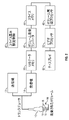
図2は、本発明の一実施形態によって形成された超音波装置を示す。装置は、送信機12と受信機14に接続されたトランスデューサ10を備える。変換器10は超音波パルスを送信し、走査した超音波画像またはボリューム16の内部の構造体からのエコーを受信する。メモリ20は走査した超音波画像またはボリューム16から派生した受信機14からの超音波データを保存する。画像またはボリューム16は様々な技術で取得することができる(例えば3D走査、実時間3D画像化、ボリューム走査、位置決めセンサを有するトランスデューサ付き2D走査、Voxel相関関係技術を使ったフリーハンド走査、2Dまたはマトリクスアレイ変換器など)。
FIG. 2 illustrates an ultrasound device formed in accordance with one embodiment of the present invention. The apparatus comprises a
トランスデューサ10は、対象領域(ROI)を走査しながら線形または円弧状のパスに沿って移動させてもよい。走査面18はメモリ20に保存され、スキャンコンバータ42に送られる。実施形態によっては、トランスデューサ10では、走査面18ではなく線を取得し、メモリ20には、走査面18ではなく、トランスデューサ10によって取得した線を保存するようにしてもよい。そして、スキャンコンバータ42は、走査面18ではなく、トランスデューサ10によって得た線を保存してもよい。また、スキャンコンバータ42は、一枚の走査面18からデータスライスを作成する。データスライスは、スライスメモリ44に保存され、ビデオプロセッサ50とディスプレイ67に送られる。
The
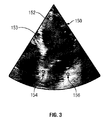
図3は、心筋の中に示される3つの生体組織の象徴部を示す画像フレーム150を示す。画像フレーム150は超音波データを含むものであるが、CT、PET、SPECT、ガンマカメラ、X線、およびMRなどのような他の画像診断モダリティを採用できるのは理解できよう。この技術は他のモダリティに適用可能ではあるが、簡素化のため、以下の説明では超音波に限定して述べることにする。画像フレーム150は、心臓組織や血液などのような少なくとも2つの異なるタイプの組織も含んでいる。他の生体組織を画像化する場合には、画像フレーム150に異なる密度の組織を含むことができる。さらに、縁部をよりよく差別化するために造影剤を使用してもよい。
FIG. 3 shows an
他のアルゴリズムや方法も使用可能ではあるが、例えばスペックルトラッキングなど、生体組織の象徴部を突き止める組織ドプラ法(TVI)を利用した方法について以下に説明する。信号処理部116は、画像の中で、例えば数百ポイント(図示せず)という、数多くのデータポイントを識別する。ポイントは生体組織の象徴部が位置すると思われる箇所に対して識別される。例示に過ぎないが、大人の心臓の先端撮影において、先端は一般にトランスデューサ106から約2cm離れた箇所に位置しており、AV面は一般にトランスデューサ106から約10cm離れた箇所に位置している。従って、予想される象徴の位置に対して識別される物理的な一般的な範囲を、データポイントを識別するための領域として識別してもよい。各画像フレーム150に対するTVI情報を分析して、各データポイントを追跡し、時間を合わせて移動や変位を判定する。データポイントは少なくとも1心拍周期の間追跡する。信号処理部116は、識別した生体組織の象徴部をライブモードで表示して追跡することができる。また、少なくとも1心拍周期分を取得して処理することができる。
Although other algorithms and methods can be used, a method using a tissue Doppler method (TVI) for locating a symbol part of a living tissue, such as speckle tracking, will be described below. The
生体組織の象徴部の1つが先端152である。先端152は先端撮影における心室153の最上点に位置する。先端は、先端撮影用トランスデューサ106に近く、心拍周期中はほとんど動かない。先端152の上には組織しかない(すなわち、血液は先端152とトランスデューサ106との間を流れることはない)。信号処理部116は画像フレーム150を通して下方向に向けて各線を走査して高いTVI値またはデータポイントの動きを突き止め、どこを血液が流れているかを識別する。また、データポイント間の明るさの違いを比較して明るい部分から暗い部分への境目を見出し、心臓組織から血液への移り変わりを識別する。
One of the symbolic parts of the living tissue is the
他の2つの生体組織の象徴部は、房室(AV)面の第1と第2の端部154,156を示す。AV面または僧帽輪は、第1と第2の端部154,156に位置する僧帽弁によって形成される面である。先端撮影では、AV面は一般的に画像フレーム150の略水平面、あるいは超音波ビームに対して90度の角度に位置する。また、僧帽輪は円形で、周知の範囲の直径を有する。さらに、一般的に、AV面は画像フレーム150内の心室の他の区分に比較して変位が大きい。よって、トランスデューサ106に空間的に離接するデータポイントの最大変位を考慮する。識別したAV面が組織内であり、血液でないことを証明するため、時間を合わせてデータポイントを追跡してもよい。組織内のデータポイントは、心拍周期の開始および終了画像フレーム150の両者において同じ位置に位置することになる。血液は高速で一方向に流れ、TVIは一部折り返し効果のため、計算することができない。さらに、血液内に形成されたデータポイントは開始および終了画像フレーム150において完全に異なる位置に位置する。
The other two tissue symbols represent the first and second ends 154, 156 of the atrioventricular (AV) surface. The AV plane or mitral ring is the plane formed by the mitral valves located at the first and second ends 154,156. In front-end imaging, the AV plane is generally positioned at a substantially horizontal plane of the
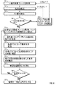
図4は、エッジ検出によって心内膜の位置を推測するための方法を示す。次の方法に従って、心内膜の位置をより正確に識別することができ、それにより、さらに正確な駆出率(EF)と他の測定値を得ることができる。ステップ160では、一連の画像フレーム150を取得する。一連の画像フレーム150には、少なくとも1心拍周期が含まれる。画像フレーム150は、例えば、シネループまたは処理済ライブなどとして保存してもよい。また、画像フレーム150は、データセットとしてRF/IQバッファ114(図1)またはメモリ20(図2)に保存してもよい。例示に過ぎないが、画像フレーム150は前述のように2DまたはTVIモードを含むものでもよい。獲得するのはここに示す態様に限定されるものでないことは理解できよう。
FIG. 4 shows a method for inferring the position of the endocardium by edge detection. According to the following method, the position of the endocardium can be more accurately identified, thereby obtaining a more accurate ejection fraction (EF) and other measurements. In
ステップ162および164では、前述のように、信号処理部116は自動的に先端152とAV面を検出する。この点において、ユーザは先端4室の撮影画像もしくは他の取得画像を検討して、生体組織の象徴部(先端152およびAV面の端部154,156)が正確に位置しているかどうかを評価する(ステップ166)。生体組織の象徴部が正しくない場合には、ステップ168に進む。ステップ168では、ユーザは、トランスデューサ106を動かして、またはユーザ入力部を使用して、正しい先端およびAV面が位置決めされるまで他の走査パラメータを選択することができる。保存されたデータセットを使用している場合は、ステップ170へ進む。あるいは、患者がまだ居れば、ステップ160へ戻り、新しい一連の画像フレーム150を取得してもよい。
In
ユーザが、生体組織の象徴部が正しいと判断したら、ステップ170へ進み、信号処理部116はその象徴部に基づいて初期のテンプレート輪郭テンプレート190を形成する。
If the user determines that the symbol part of the living tissue is correct, the process proceeds to step 170, and the
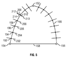
図5は、輪郭テンプレート、または輪郭テンプレート190を示す図であり、識別された先端152とAV面158の第1と第2の端部154および156とともに示す。信号処理部116は、輪郭テンプレート190をAV面の第1の端部154から先端152まで、および先端152から第2の端部156まで伸びる曲線として定義している。AV面158は、第1と第2の端部154,156を結合する線として示す。輪郭テンプレート190と、AV面158を示す線は表示118上に必ずしも表示されるわけではなく、アルゴリズムによって初期の輪郭として使用することができる。
FIG. 5 is a diagram showing a contour template, or
図4に戻り、ステップ172において、一連の点192−200を輪郭テンプレートに沿って定義する。例示に過ぎないが点192−200の数は40以下であってもよい。点192−200の位置は信号処理部116によって予め定義することができ、また、走査している生体組織または生体組織の一部に依存する。次に、信号処理部116は、各点192−200において輪郭テンプレート190を2等分するパス202−210を定義する。
Returning to FIG. 4, in
ステップ174では、信号処理部116は各パス202−210に沿った候補となる点212−216を定義する。各パス202−210には、それ以上または以下の数でもよいが、20個の候補点212−216を設けてもよい。先に輪郭テンプレート190と横パス202−210の交差点を定義した点192−200を候補点として使用してもよい。図5では、分かりやすいように、輪郭テンプレート190に沿ったすべての点、パス、および候補点に対しては識別、符号表記をしていない。
In
ステップ176では、各パス202−210に沿った各候補点212−216を分析してスコア(数またはコスト)を判定する。スコアは部分的に生体組織の所定の特徴に基づくものでよい。例えば、パスに沿ったすべての候補点212−216の強度または明度を互いに比較する。候補点212−216の強度を比較してパス210の最も明るい領域と最も暗い領域を求める。超音波では、一般的に組織は血液より明るい。よって、パス210に沿った心内膜の定義に最も適した境界を、2つ以上の隣接する候補点200および212−216の間の、暗から明への明度の差が最も大きい部分として識別することができる。例えば、パス210上で6,8,10の隣接する点を比較する。各候補点200および212−216はその隣との明度の比較に基づいてスコアを与えられる。このスコアは、後に心内膜の位置を突き止める方法において使用する。
In
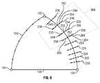
図6は、輪郭テンプレート190とパス220−236を候補点238−266とともに示す。分かりやすいように、すべてのパス上の候補点すべてに番号を付してはいない。
FIG. 6 shows the
図4のステップ178では、信号処理部116がパス220−236の間の候補点238−266を分析して各パス220−236の最良の境界点を判定する。この境界点は、この方法を実行している間で、この心内膜の最良の位置を定義するものである。一連の境界点は、最良のパスを定義するものであり、外側の明るい部分が組織を示し内側の暗い部分が血液を示す。
In
検索領域268は、2つ以上の連続するパス220−236の周囲を定義すればよい。例えば、候補点238−266は三つの連続的パス230−234に沿って分析することができる。パス230−234それぞれについて1つ、合計3つの候補点238−266の各組み合わせを比較し、可能なパスに沿った角度、もしくは3つの候補点238−266の間の輪郭の円滑性に基づいてコストが割り当てられる。ステップ176で先に割り当てられた、縁部上(暗から明への境界)にあることを示すコストも考慮される。例えば「238,248,258」「238,248,260」、「238,248,262」、「238,248,264」、および「238,248,266」のような3つの候補点の組は、互いに対して分析する。また、例えば「238,248」「238,250」「238,252」「238,254」のような2つの候補点の組は輪郭テンプレートに対して分析して円滑性を予測する。最も円滑となる最良の組合せを有する各パス220−236上および縁部上における候補点238−266は最も好ましいコストが割り当てられるので、境界点として定義することができる。例えば、候補点244,252および260は、検索領域268の中で、パス230−234それぞれに対する境界点として割り振ることができる。
The
よって、信号処理部116は輪郭テンプレート190に沿って第1の端部154から先端152、そして第2の端部156まで走査して最良のパスを見出す。検索領域268は端部154から先端152まで、そして端部156まで輪郭テンプレート190に沿って移動するので、それぞれの2つもしくは3つの候補点238−266の組合せは、それぞれの2つまたは3つの連続的パス220−236に沿って分析される。そしてステップ176および178の分析でコストを最低限に抑えるパスを選択する。
Thus, the
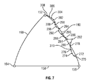
図7は、新しい輪郭またはパス310を定義する、図4のステップ178で判定した境界点270−308を示す。パス310は、先にユーザまたは超音波装置100で描いた輪郭テンプレートより心筋の輪郭に厳密に追従する。
FIG. 7 shows the boundary points 270-308 determined in
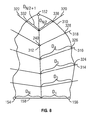
図4に戻り、ステップ180では、信号処理部116はパス310を空間的に円滑にする。図8は、パス310と共に画像フレーム150を示しており、先の図7に示した心内膜を表す。LV主要線312を先端152からAV面158の中心点まで引く。線314−322をLV主要線312から外側に向かって引く。使用する直線314−322の数は増やしてもよいことは理解できよう。
Returning to FIG. 4, in
信号処理部116は各線314−322とパス310もしくは心内膜の間の交差点を識別する。例えば、交差点330は、線320とパス310の間の交差点として識別される。
The
交差点324−332を識別したら、信号処理部116は交差点324−332からLV主要線312までの距離Dを各線314−322に沿って計算する。従って、線316に対しては、距離D4を計算する。D1−D4のような距離を、各線314−322に対して算出し、テーブルフォーマットへ保存してもよい。
Once the intersections 324-332 are identified, the
距離D1−D4は、空間内で円滑化されて円滑な外観を作り上げる。円滑化はパス310に沿って連続する距離の移動平均または中点を計算することによって行う。あるいは、他の線形または非線形フィルタを使用してもよい。例えば、3つの連続的距離、例えば距離D1、D2、D3を平均化して円滑な輪郭を作成することができる。平均化した連続的距離を利用して、交差点324,326,328,330,および332に対してできる限り新しい位置を算出することによってより円滑なパスを作成することができる。距離D1−D4を平均化することによって、パス310に沿った連続的な交差点のうち、隣接する交差点と比較すると大幅に異なる点は修正される(例えば図7の境界点282)。結果得られた輪郭または新しいパス310は表、データセットまたはベクトルフォーマットに、各画像フレーム150に対する新しいセットの距離D1A−D4Aとして保存してもよい。新しいセットの距離D1A−D4Aは、後述の図9の表1のように、各画像フレーム150の心筋の位置を表す。
The distances D 1 -D 4 are smoothed in the space to create a smooth appearance. Smoothing is done by calculating a moving average or midpoint of consecutive distances along
図4に戻り、信号処理部116はステップ182で一連のフレーム150のうちさらに別のフレーム150を処理するかどうかを判定する。する場合には残りの画像フレーム150がそれぞれ処理されるまでステップ170に戻る。処理部は次の連続的画像フレームに対し、コスト機能のうちの一つとして前の画像フレームに対して識別した輪郭を使用する。処理する画像フレーム150が残っていない場合はステップ184に進む。
Returning to FIG. 4, in
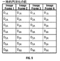
図9および図10は、画像フレーム150の輪郭を表す距離測定値を示す2つの表を示す。図9に示す表は、処理した画像フレーム150(ステップ180以降)に対する距離測定値を示し、図10に示す表は、輪郭を一時的に円滑化した後(ステップ184以降)の平均距離測定値を示す。画像フレーム1は、画像フレーム2に隣接し、画像フレーム2は、画像フレーム3に隣接する(以下同様)。タイミングよく輪郭を一時的に円滑化するには、信号処理部116は画像フレーム1、2および3に対して中点フィルタを使用して表1の値D1Aをフィルタにかけ、フィルタにかけた値を画像フレーム2の表2に保存する。あるいは、4つ以上の連続的輪郭をフィルタにかけてもよい。一実施形態として、信号処理部116は、画像フレーム2の表2の値D1AVEを使って、画像フレーム3,4,などに対して表1のD1A値でフィルタにかけてもよい。あるいは、中点フィルタを使用する代わりに、平均フィルタなどのような他の非線形または線形フィルタを使用してもよい。
9 and 10 show two tables showing distance measurements representing the contour of the
表2に保存した距離の値はその心拍周期内の各画像フレーム150に対する心内膜の輪郭に対する最終値を表す。シネループ内の表2の値によって定義されたパス310を表示する場合には、パス310は画像フレーム150から画像フレーム150への心内膜の変化に厳密に追従し、輪郭は表示装置上118において円滑で激しい変化のない様相を呈するようになる。すべての画像フレーム150の輪郭が決まったら、例えばシンプソン法を使って心室の容量を推測する。1心拍周期中で最小の予測心室容積を有する画像フレーム150を拡張末期フレームとして定義する。心室推測容積が最大の画像フレーム150を拡張最終容積として定義する。オプションで、ECG情報を使ってEDとESフレームを選択してもよい。例えば、ECG三角点後の最初のフレームをEDフレームとして定義してもよい。ユーザはユーザ入力部120を使用して異なる画像フレームを正しいEDまたはES輪郭として手動で選択するか、あるいは、1つ以上の画像フレーム150の輪郭もしくは輪郭の一部を移動もしくは再描画するか、先端を移動するか、AV面を移動するか、輪郭の部分を再描画するか、あるいはタイミングを変える。シネループはすべてのフレームにおいて同じ位置にあるため、動いている間に先端を移動させることができる。新しい先端の位置を指定したら、縁部検出が自動的に再起動する。AV面が移動しているので、ループが動いている間は修正ができない。先端の検出が首尾よく終了したら、ボタンを押してEDフレームへ移動する。ユーザは回転ボタンまたは押しボタンを押してEDおよびESフレーム間をジャンプしたり、シネループ内で前後に適当なタイミングでスクロールして輪郭を再検討したりすることができる。ユーザは、影があるなどの理由から装置が適当な境界を発見できない場合には手動で輪郭の一部を描画することもできる。輪郭を手動で修正したら、表2の中の値はそれに従って更新される。
The distance values stored in Table 2 represent the final values for the endocardial contour for each
表2に保存した値をここで超音波装置の測定パッケージで使用することができる。輪郭またはパス310で形成された領域は心室の容積を表し、それを使ってシンプソン法などによって駆出率を算出することができる。ストローク容積CO,CI,MRE,E′,A′およびVSも計算できる。さらに、複数の心拍サイクルの平均を出したい場合には、先に計算したデータを保存して追加のデータと合成すればよい。
The values stored in Table 2 can now be used in the measurement package of the ultrasound device. The region formed by the contour or
よって、パス310がこれまでの描画法および自動検出法に比較して心内膜に厳密に追従するので、パス310に基づいた計算がより正確になる。当業者はここで説明した方法と装置がMRIのような他の画像化の様相および心室以外の生体構造に適用できることは理解できよう。さらに、心臓の他の部分の撮影画像も長軸および大動脈弁を象徴部として使用することなどによってすることができる。また、経食道トランスデューサを使用して心臓を観察することもでき、その場合には象徴部検出を調整しなければならない。
Therefore, since the
本発明は様々な特定の実施形態について説明してきたが、当業者は、本発明が請求の範囲の精神と範囲内において変更が可能であることは理解できよう。 While the invention has been described in terms of various specific embodiments, those skilled in the art will recognize that the invention can be modified within the spirit and scope of the claims.
116 信号処理部
150 画像フレーム
190 輪郭テンプレート
Claims (16)
Applications Claiming Priority (1)
| Application Number | Priority Date | Filing Date | Title |
|---|---|---|---|
| US10/822,935 US7678052B2 (en) | 2004-04-13 | 2004-04-13 | Method and apparatus for detecting anatomic structures |
Publications (2)
| Publication Number | Publication Date |
|---|---|
| JP2005296658A true JP2005296658A (en) | 2005-10-27 |
| JP2005296658A5 JP2005296658A5 (en) | 2008-05-22 |
Family
ID=35061477
Family Applications (1)
| Application Number | Title | Priority Date | Filing Date |
|---|---|---|---|
| JP2005111671A Pending JP2005296658A (en) | 2004-04-13 | 2005-04-08 | Method and apparatus for detecting tissue structure |
Country Status (3)
| Country | Link |
|---|---|
| US (1) | US7678052B2 (en) |
| JP (1) | JP2005296658A (en) |
| DE (1) | DE102005016944A1 (en) |
Cited By (3)
| Publication number | Priority date | Publication date | Assignee | Title |
|---|---|---|---|---|
| JP2008142519A (en) * | 2006-11-14 | 2008-06-26 | Aloka Co Ltd | Ultrasonic diagnostic apparatus and volume data processing method |
| JP2010017530A (en) * | 2008-06-13 | 2010-01-28 | Canon Inc | Ultrasonic apparatus and control method therefor |
| JP2011504629A (en) * | 2007-11-22 | 2011-02-10 | トウシバメディカルビジュアライゼーションシステムズヨーロッパ・リミテッド | Volume rendering apparatus and method |
Families Citing this family (42)
| Publication number | Priority date | Publication date | Assignee | Title |
|---|---|---|---|---|
| US20060058675A1 (en) * | 2004-08-31 | 2006-03-16 | General Electric Company | Three dimensional atrium-ventricle plane detection |
| US20060058609A1 (en) * | 2004-08-31 | 2006-03-16 | General Electric Company | Extracting ultrasound summary information useful for inexperienced users of ultrasound |
| US7555151B2 (en) * | 2004-09-02 | 2009-06-30 | Siemens Medical Solutions Usa, Inc. | System and method for tracking anatomical structures in three dimensional images |
| DE102004043058A1 (en) * | 2004-09-06 | 2006-04-06 | Siemens Ag | Method for the determination of excellent coronal and sagittal planes for the subsequent acquisition of new magnetic resonance slice images or the representation of magnetic resonance slice images from an already existing image data set of a shoulder joint |
| US7724929B2 (en) * | 2005-10-17 | 2010-05-25 | Siemens Medical Solutions Usa, Inc. | System and method for myocardium segmentation in realtime cardiac MR data |
| US20080009733A1 (en) * | 2006-06-27 | 2008-01-10 | Ep Medsystems, Inc. | Method for Evaluating Regional Ventricular Function and Incoordinate Ventricular Contraction |
| US7728868B2 (en) | 2006-08-02 | 2010-06-01 | Inneroptic Technology, Inc. | System and method of providing real-time dynamic imagery of a medical procedure site using multiple modalities |
| US20080086053A1 (en) * | 2006-10-06 | 2008-04-10 | Siemens Corporate Research, Inc. | Component-Based Approach For Fast Left Ventricle Detection |
| EP2026280B1 (en) * | 2007-07-23 | 2013-10-23 | Esaote S.p.A. | Method and corresponding apparatus for quantitative measurements on sequences of images, particularly ultrasonic images |
| US20090105578A1 (en) * | 2007-10-19 | 2009-04-23 | Siemens Medical Solutions Usa, Inc. | Interactive Medical Imaging Processing and User Interface System |
| US20110105931A1 (en) * | 2007-11-20 | 2011-05-05 | Siemens Medical Solutions Usa, Inc. | System for Determining Patient Heart related Parameters for use in Heart Imaging |
| WO2009094646A2 (en) | 2008-01-24 | 2009-07-30 | The University Of North Carolina At Chapel Hill | Methods, systems, and computer readable media for image guided ablation |
| WO2009132188A1 (en) * | 2008-04-24 | 2009-10-29 | Boston Scientific Scimed, Inc. | Methods, systems, and devices for tissue characterization by spectral similarity of intravascular ultrasound signals |
| US9549713B2 (en) | 2008-04-24 | 2017-01-24 | Boston Scientific Scimed, Inc. | Methods, systems, and devices for tissue characterization and quantification using intravascular ultrasound signals |
| US8444564B2 (en) | 2009-02-02 | 2013-05-21 | Jointvue, Llc | Noninvasive diagnostic system |
| US11464578B2 (en) | 2009-02-17 | 2022-10-11 | Inneroptic Technology, Inc. | Systems, methods, apparatuses, and computer-readable media for image management in image-guided medical procedures |
| US8554307B2 (en) | 2010-04-12 | 2013-10-08 | Inneroptic Technology, Inc. | Image annotation in image-guided medical procedures |
| US8690776B2 (en) | 2009-02-17 | 2014-04-08 | Inneroptic Technology, Inc. | Systems, methods, apparatuses, and computer-readable media for image guided surgery |
| US8641621B2 (en) | 2009-02-17 | 2014-02-04 | Inneroptic Technology, Inc. | Systems, methods, apparatuses, and computer-readable media for image management in image-guided medical procedures |
| DE102009014763B4 (en) * | 2009-03-25 | 2018-09-20 | Siemens Healthcare Gmbh | Method and data processing system for determining the calcium content in coronary vessels |
| US9002078B2 (en) * | 2009-10-22 | 2015-04-07 | Siemens Aktiengesellschaft | Method and system for shape-constrained aortic valve landmark detection |
| GB2475722B (en) * | 2009-11-30 | 2011-11-02 | Mirada Medical | Measurement system for medical images |
| US10512451B2 (en) | 2010-08-02 | 2019-12-24 | Jointvue, Llc | Method and apparatus for three dimensional reconstruction of a joint using ultrasound |
| US20130225987A1 (en) * | 2010-09-20 | 2013-08-29 | Stephen Yarnall | Dedicated breast imaging with improved gamma-ray collection |
| WO2013025613A1 (en) | 2011-08-12 | 2013-02-21 | Jointvue, Llc | 3-d ultrasound imaging device and methods |
| CA3194212A1 (en) | 2011-10-14 | 2013-04-18 | Jointvue, Llc | Real-time 3-d ultrasound reconstruction of knee and its implications for patient specific implants and 3-d joint injections |
| US8670816B2 (en) | 2012-01-30 | 2014-03-11 | Inneroptic Technology, Inc. | Multiple medical device guidance |
| US9747306B2 (en) | 2012-05-25 | 2017-08-29 | Atheer, Inc. | Method and apparatus for identifying input features for later recognition |
| US10314559B2 (en) | 2013-03-14 | 2019-06-11 | Inneroptic Technology, Inc. | Medical device guidance |
| KR20150108701A (en) | 2014-03-18 | 2015-09-30 | 삼성전자주식회사 | System and method for visualizing anatomic elements in a medical image |
| KR101616029B1 (en) | 2014-07-25 | 2016-04-27 | 삼성전자주식회사 | Magnetic resonance imaging processing method and apparatus thereof |
| CN104188691A (en) * | 2014-09-23 | 2014-12-10 | 飞依诺科技(苏州)有限公司 | Method and system for auxiliary navigation positioning of ultrasonic images |
| US9901406B2 (en) | 2014-10-02 | 2018-02-27 | Inneroptic Technology, Inc. | Affected region display associated with a medical device |
| US10188467B2 (en) | 2014-12-12 | 2019-01-29 | Inneroptic Technology, Inc. | Surgical guidance intersection display |
| CN117179817A (en) | 2015-05-05 | 2023-12-08 | 波士顿科学国际有限公司 | System and method with expandable material disposed on transducer of ultrasound imaging system |
| US9949700B2 (en) | 2015-07-22 | 2018-04-24 | Inneroptic Technology, Inc. | Medical device approaches |
| US9675319B1 (en) | 2016-02-17 | 2017-06-13 | Inneroptic Technology, Inc. | Loupe display |
| US10278778B2 (en) | 2016-10-27 | 2019-05-07 | Inneroptic Technology, Inc. | Medical device navigation using a virtual 3D space |
| US11259879B2 (en) | 2017-08-01 | 2022-03-01 | Inneroptic Technology, Inc. | Selective transparency to assist medical device navigation |
| US11484365B2 (en) | 2018-01-23 | 2022-11-01 | Inneroptic Technology, Inc. | Medical image guidance |
| US11931202B2 (en) * | 2018-09-03 | 2024-03-19 | Canon Medical Systems Corporation | Ultrasound automatic scanning system, ultrasound diagnostic apparatus, ultrasound scanning support apparatus |
| JP7294996B2 (en) * | 2019-11-28 | 2023-06-20 | 富士フイルムヘルスケア株式会社 | Ultrasound diagnostic device and display method |
Citations (3)
| Publication number | Priority date | Publication date | Assignee | Title |
|---|---|---|---|---|
| JPH05143734A (en) * | 1991-11-20 | 1993-06-11 | Yamatake Honeywell Co Ltd | Part contour extraction method |
| WO2002045586A1 (en) * | 2000-12-07 | 2002-06-13 | Koninklijke Philips Electronics N.V. | Acquisition, analysis and display of ultrasonic diagnostic cardiac images |
| JP2002291750A (en) * | 2001-03-30 | 2002-10-08 | Yoshihiro Sasaki | Tumor boundary display device in ultrasonic image |
Family Cites Families (5)
| Publication number | Priority date | Publication date | Assignee | Title |
|---|---|---|---|---|
| US6106466A (en) * | 1997-04-24 | 2000-08-22 | University Of Washington | Automated delineation of heart contours from images using reconstruction-based modeling |
| US6106465A (en) * | 1997-08-22 | 2000-08-22 | Acuson Corporation | Ultrasonic method and system for boundary detection of an object of interest in an ultrasound image |
| US6491636B2 (en) * | 2000-12-07 | 2002-12-10 | Koninklijke Philips Electronics N.V. | Automated border detection in ultrasonic diagnostic images |
| US20030160786A1 (en) * | 2002-02-28 | 2003-08-28 | Johnson Richard K. | Automatic determination of borders of body structures |
| US7359554B2 (en) * | 2002-08-26 | 2008-04-15 | Cleveland Clinic Foundation | System and method for identifying a vascular border |
-
2004
- 2004-04-13 US US10/822,935 patent/US7678052B2/en active Active
-
2005
- 2005-04-08 JP JP2005111671A patent/JP2005296658A/en active Pending
- 2005-04-12 DE DE102005016944A patent/DE102005016944A1/en not_active Ceased
Patent Citations (3)
| Publication number | Priority date | Publication date | Assignee | Title |
|---|---|---|---|---|
| JPH05143734A (en) * | 1991-11-20 | 1993-06-11 | Yamatake Honeywell Co Ltd | Part contour extraction method |
| WO2002045586A1 (en) * | 2000-12-07 | 2002-06-13 | Koninklijke Philips Electronics N.V. | Acquisition, analysis and display of ultrasonic diagnostic cardiac images |
| JP2002291750A (en) * | 2001-03-30 | 2002-10-08 | Yoshihiro Sasaki | Tumor boundary display device in ultrasonic image |
Cited By (4)
| Publication number | Priority date | Publication date | Assignee | Title |
|---|---|---|---|---|
| JP2008142519A (en) * | 2006-11-14 | 2008-06-26 | Aloka Co Ltd | Ultrasonic diagnostic apparatus and volume data processing method |
| JP2011504629A (en) * | 2007-11-22 | 2011-02-10 | トウシバメディカルビジュアライゼーションシステムズヨーロッパ・リミテッド | Volume rendering apparatus and method |
| JP2010017530A (en) * | 2008-06-13 | 2010-01-28 | Canon Inc | Ultrasonic apparatus and control method therefor |
| CN102056548B (en) * | 2008-06-13 | 2013-02-13 | 佳能株式会社 | Ultrasonic apparatus and control method thereof |
Also Published As
| Publication number | Publication date |
|---|---|
| DE102005016944A1 (en) | 2005-11-03 |
| US7678052B2 (en) | 2010-03-16 |
| US20050228254A1 (en) | 2005-10-13 |
Similar Documents
| Publication | Publication Date | Title |
|---|---|---|
| JP2005296658A (en) | Method and apparatus for detecting tissue structure | |
| US8050478B2 (en) | Method and apparatus for tissue border detection using ultrasonic diagnostic images | |
| CN110477952B (en) | Ultrasonic diagnostic apparatus, medical image diagnostic apparatus, and storage medium | |
| US8167802B2 (en) | Biological tissue motion trace method and image diagnosis device using the trace method | |
| US6491636B2 (en) | Automated border detection in ultrasonic diagnostic images | |
| JP4152746B2 (en) | Ultrasound diagnostic cardiac image capture, analysis and display method | |
| US6994673B2 (en) | Method and apparatus for quantitative myocardial assessment | |
| US11510651B2 (en) | Ultrasonic diagnosis of cardiac performance using heart model chamber segmentation with user control | |
| JP5276322B2 (en) | Ultrasound diagnostic method and apparatus for ischemic heart disease | |
| US6537221B2 (en) | Strain rate analysis in ultrasonic diagnostic images | |
| JPH1142227A (en) | Tracking of motion of tissue and ultrasonic image processor | |
| WO2017206023A1 (en) | Cardiac volume identification analysis system and method | |
| WO2007016369A2 (en) | System and method for cardiac imaging | |
| JP2015156960A (en) | Ultrasonic diagnostic equipment | |
| CN116883322A (en) | Method and terminal for measuring and managing heart parameters by using three-dimensional ultrasonic model | |
| JP5015513B2 (en) | Integrated ultrasound device for measurement of anatomical structures | |
| RU2708317C2 (en) | Ultrasound diagnosis of cardiac function by segmentation of a chamber with one degree of freedom | |
| EP4366623B1 (en) | Augmented imaging for valve repair | |
| JP4528247B2 (en) | Ultrasonic diagnostic apparatus and ultrasonic image processing method | |
| US12514545B2 (en) | Completeness of view of anatomy in ultrasound imaging and associated systems, devices, and methods | |
| JP6745210B2 (en) | Ultrasonic image processing apparatus and method |
Legal Events
| Date | Code | Title | Description |
|---|---|---|---|
| A521 | Request for written amendment filed |
Free format text: JAPANESE INTERMEDIATE CODE: A523 Effective date: 20080404 |
|
| A621 | Written request for application examination |
Free format text: JAPANESE INTERMEDIATE CODE: A621 Effective date: 20080404 |
|
| A977 | Report on retrieval |
Free format text: JAPANESE INTERMEDIATE CODE: A971007 Effective date: 20101021 |
|
| A131 | Notification of reasons for refusal |
Free format text: JAPANESE INTERMEDIATE CODE: A131 Effective date: 20101026 |
|
| A601 | Written request for extension of time |
Free format text: JAPANESE INTERMEDIATE CODE: A601 Effective date: 20110119 |
|
| RD02 | Notification of acceptance of power of attorney |
Free format text: JAPANESE INTERMEDIATE CODE: A7422 Effective date: 20110119 |
|
| RD04 | Notification of resignation of power of attorney |
Free format text: JAPANESE INTERMEDIATE CODE: A7424 Effective date: 20110119 |
|
| A602 | Written permission of extension of time |
Free format text: JAPANESE INTERMEDIATE CODE: A602 Effective date: 20110125 |
|
| A02 | Decision of refusal |
Free format text: JAPANESE INTERMEDIATE CODE: A02 Effective date: 20110628 |