JP2005296621A - Suction brush assembly and vacuum cleaner provided with the same - Google Patents
Suction brush assembly and vacuum cleaner provided with the same Download PDFInfo
- Publication number
- JP2005296621A JP2005296621A JP2004334974A JP2004334974A JP2005296621A JP 2005296621 A JP2005296621 A JP 2005296621A JP 2004334974 A JP2004334974 A JP 2004334974A JP 2004334974 A JP2004334974 A JP 2004334974A JP 2005296621 A JP2005296621 A JP 2005296621A
- Authority
- JP
- Japan
- Prior art keywords
- suction
- brush assembly
- rotating body
- cover
- turbine fan
- Prior art date
- Legal status (The legal status is an assumption and is not a legal conclusion. Google has not performed a legal analysis and makes no representation as to the accuracy of the status listed.)
- Pending
Links
Images

Classifications
-
- A—HUMAN NECESSITIES
- A47—FURNITURE; DOMESTIC ARTICLES OR APPLIANCES; COFFEE MILLS; SPICE MILLS; SUCTION CLEANERS IN GENERAL
- A47L—DOMESTIC WASHING OR CLEANING; SUCTION CLEANERS IN GENERAL
- A47L9/00—Details or accessories of suction cleaners, e.g. mechanical means for controlling the suction or for effecting pulsating action; Storing devices specially adapted to suction cleaners or parts thereof; Carrying-vehicles specially adapted for suction cleaners
- A47L9/0081—Means for exhaust-air diffusion; Means for sound or vibration damping
-
- A—HUMAN NECESSITIES
- A47—FURNITURE; DOMESTIC ARTICLES OR APPLIANCES; COFFEE MILLS; SPICE MILLS; SUCTION CLEANERS IN GENERAL
- A47L—DOMESTIC WASHING OR CLEANING; SUCTION CLEANERS IN GENERAL
- A47L9/00—Details or accessories of suction cleaners, e.g. mechanical means for controlling the suction or for effecting pulsating action; Storing devices specially adapted to suction cleaners or parts thereof; Carrying-vehicles specially adapted for suction cleaners
- A47L9/02—Nozzles
- A47L9/04—Nozzles with driven brushes or agitators
- A47L9/0405—Driving means for the brushes or agitators
- A47L9/0416—Driving means for the brushes or agitators driven by fluid pressure, e.g. by means of an air turbine
Landscapes
- Engineering & Computer Science (AREA)
- Mechanical Engineering (AREA)
- Nozzles For Electric Vacuum Cleaners (AREA)
- Electric Suction Cleaners (AREA)
Abstract
【課題】 内部に塵埃などが流入されるのを防止することで掃除効率を向上させることができるように構造が改善された吸入ブラシおよびこれを備えた真空掃除機を提供する。
【解決手段】 本発明に係る吸入ブラシ組立体は、被掃除面上の塵埃などを吸入する吸入口が設けられたボディと、前記ボディに結合され、外部空気が吸入されるように開口が形成されたカバーと、前記ボディに回転可能に設けられ、下部に被掃除面と接触する掃除部材が着脱可能に装着される回転体とを備える。
【選択図】 図4PROBLEM TO BE SOLVED: To provide a suction brush whose structure is improved so that cleaning efficiency can be improved by preventing dust and the like from flowing inside, and a vacuum cleaner provided with the suction brush.
A suction brush assembly according to the present invention includes a body provided with a suction port for sucking dust and the like on a surface to be cleaned, and an opening that is coupled to the body and sucks external air. And a rotating body that is rotatably provided on the body and on which a cleaning member that contacts the surface to be cleaned is detachably mounted.
[Selection] Figure 4
Description
本発明は、真空掃除機の吸入ブラシ組立体に関し、より詳しくは、掃除の効率を向上させると共に騒音を低減させることができるように構造が改善された吸入ブラシ組立体およびこれを備えた真空掃除機に関する。 The present invention relates to a suction brush assembly of a vacuum cleaner, and more particularly, to a suction brush assembly having an improved structure so as to improve cleaning efficiency and reduce noise, and a vacuum cleaner having the same. Related to the machine.
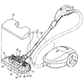
図1は、一般の真空掃除機を概略的に示す分解斜視図である。図1を参照するに、一般に、真空掃除機は、吸入力を発生するモータが内蔵された真空掃除機本体1、本体1に連結される延長流路10、および延長流路10に連結され、被掃除面上の塵埃などを吸入するための吸入ブラシ組立体20を備えてなる。
FIG. 1 is an exploded perspective view schematically showing a general vacuum cleaner. Referring to FIG. 1, generally, a vacuum cleaner is connected to a vacuum cleaner body 1 having a built-in motor for generating suction input, an
延長流路10は、吸入ブラシ組立体20に連結される延長管コネクタ12、延長管コネクタ12に連結される延長管14、および一端は延長管14に連結され、他端は真空掃除機本体1に連結される吸入ホース16を含む。このような構造を採ることで、吸入ブラシ組立体20から吸入された塵埃などは延長管コネクタ12、延長管14、吸入ホース16を順に経て真空掃除機本体1に設けられた集塵室(図示省略)に捕集される。
The
吸入ブラシ組立体20は、カバー22、カバー22に結合され、下面に吸入口36が形成されたボディ30、ボディ30に回転可能に設けられるタービンファン90、下端に雑巾のような掃除部材82が装着される回転体80、回転体80の上部に形成されるウォームホイール74、ウォームホイール74に対応し、タービンファン90と同軸上から左右に延びる軸上に形成されるウォーム72を含む。回転体80は、ボディ30に形成された回転体収納室38の回転体取付ボス40に回転可能に取り付けられる。
The suction brush assembly 20 includes a
前述のような構造で真空掃除機本体1に内蔵されたモータ(図示省略)が作動すると、ボディ30の下部に形成された吸入口36に吸入力が形成され、被掃除面上の塵埃などを含む空気を吸入するようになる。吸入された空気は、タービンファン90に形成されたタービンブレード92にぶつかってタービンファン90を回転させるようになる。タービンファン90が回転すると、タービンファン90と同軸上に形成されたウォーム72が回転し、このウォーム72は、ウォームホイール74に動力を伝達する。ウォームホイール74に伝達された動力は、ウォームホイール74と一体に形成された回転体80を回転させ、これにより、回転体80の下部に装着される掃除部材82が回転するようになる。このような掃除部材82の回転により被掃除面の塵埃などをより効率良く掃除することが可能となる。
When a motor (not shown) built in the vacuum cleaner main body 1 with the above-described structure is activated, a suction input is formed in the
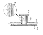
しかし、図2に示されたように、回転体80が回転して掃除部材82が被掃除面を掃除しながら回転体収納室38(図1参照)の底面板39と回転体80の掃除部材装着部84との間に塵埃などが流入される。流入された塵埃は、回転体80と回転体取付ボス40との間に溜まるだけでなく、回転体収納室38まで流入され、ウォーム72(図1参照)およびウォームホイール74(図1参照)にも溜まるようになる。このような塵埃の流入により回転体80の円滑な回転ができなくなり、これによって、回転体80と共に回転する掃除部材82が円滑に被掃除面の塵埃などを拭き取ることができなくなる。即ち、掃除効率が低下してしまう。
However, as shown in FIG. 2, the rotating
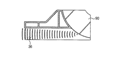
また、図3に示されたように、吸入口36とタービンファン90までの到達距離が短いため、タービンファン90および各種の部品から発生する騒音は、吸入部36を介して吸入ブラシ組立体20の外部に放出される。外部に放出された騒音は、使用者に伝達され、使用者が不快感を感じるようになる。特に、高周波領域帯の騒音に敏感に反応する。
Further, as shown in FIG. 3, since the reach distance between the
本発明は、上記のような問題点を解決するためになされたものであって、本発明の目的は、内部に塵埃などが流入されるのを防止することで掃除効率を向上させることができるように構造が改善された吸入ブラシ組立体およびこれを備えた真空掃除機を提供することにある。 The present invention has been made to solve the above-described problems, and an object of the present invention is to improve cleaning efficiency by preventing dust and the like from flowing inside. It is an object of the present invention to provide a suction brush assembly having an improved structure and a vacuum cleaner provided with the same.
本発明の他の目的は、タービンファンおよび各種の部品から発生する高周波領域帯の騒音を低減することができるように構造が改善された吸入ブラシ組立体およびこれを備えた真空掃除機を提供することにある。 Another object of the present invention is to provide a suction brush assembly having an improved structure and a vacuum cleaner provided with the suction brush assembly so as to reduce high-frequency band noise generated from a turbine fan and various components. There is.
前述の目的を達成するための本発明に係る吸入ブラシ組立体は、被掃除面上の塵埃などを吸入する吸入口が形成されたボディと、前記ボディに結合され、外部空気が吸入されるように開口が形成されたカバーと、前記ボディに回転可能に設けられ、下部に被掃除面と接触する掃除部材が着脱可能に設けられる回転体とを含み、前記開口から吸入された外部空気が前記回転体と前記ボディとの間に形成された結合隙間を通過して前記ボディの下部に流出されることを特徴とする。 In order to achieve the above object, a suction brush assembly according to the present invention includes a body formed with a suction port for sucking dust and the like on a surface to be cleaned, and is coupled to the body so that external air is sucked. A cover having an opening formed therein, and a rotating body rotatably provided on the body and provided with a cleaning member in contact with a surface to be cleaned in a detachable manner, and external air sucked from the opening is It passes through the coupling gap formed between the rotating body and the body and flows out to the lower part of the body.
また、本発明の目的は、被掃除面上の塵埃などを吸入する吸入口が形成されたボディと、前記ボディに結合されるカバーと、前記ボディに回転可能に設けられたタービンファンと、前記吸入口から吸入された空気を前記タービンファンに案内する吸入流路と、前記吸入流路を形成し、複数の貫通孔が形成された流路隔壁とを備える吸入ブラシ組立体により達成することができる。従って、前記回転体と前記ボディとの間の結合隙間を介して塵埃などが流入されるのを防止することができるため、掃除効率が向上し、タービンファンと各種の部品から発生する高周波騒音を低減させることができる。 Another object of the present invention is to provide a body formed with a suction port for sucking dust or the like on the surface to be cleaned, a cover coupled to the body, a turbine fan rotatably provided on the body, This can be achieved by a suction brush assembly that includes a suction flow path that guides air sucked from a suction port to the turbine fan, and a flow path partition that forms the suction flow path and has a plurality of through holes. it can. Accordingly, since dust and the like can be prevented from flowing through the coupling gap between the rotating body and the body, the cleaning efficiency is improved, and high-frequency noise generated from the turbine fan and various parts is reduced. Can be reduced.
本発明の実施例に係る吸入ブラシ組立体は、吸入口が形成されたボディと、前記ボディに回転可能に設けられ、その下部には被掃除面を拭き取るように掃除部材が着脱可能に装着される回転体と、前記回転体を覆うように前記ボディに結合され、外部空気が流入されるように第1の開口が形成された第1のカバーと、前記第1のカバーの上部に位置するように前記ボディに結合され、第2の開口が形成された第2のカバーと、前記ボディに回転可能に設けられるタービンファンと、前記タービンファンの動力を前記回転体に伝達するウォームおよびウォームホイールと、吸入流路を形成するように前記ボディに設けられ、複数の貫通孔が形成された流路形成部材と、前記貫通孔を覆うように前記流路形成部材に取り付けられる吸音材とを備えてなる。 A suction brush assembly according to an embodiment of the present invention includes a body having a suction port formed therein, and is rotatably provided in the body, and a cleaning member is detachably attached to a lower portion of the suction brush assembly so as to wipe a surface to be cleaned. A rotating body, a first cover coupled to the body so as to cover the rotating body, and having a first opening formed to allow external air to flow in, and an upper portion of the first cover A second cover that is coupled to the body and has a second opening, a turbine fan that is rotatably provided in the body, and a worm and a worm wheel that transmit power of the turbine fan to the rotating body And a flow path forming member provided in the body so as to form a suction flow path and formed with a plurality of through holes, and a sound absorbing material attached to the flow path forming member so as to cover the through holes. It made.
前述のような構造で第2の開口および第1の開口を介して吸入された外部空気は、前記回転体と前記ボディに形成された回転体取付ボスとの間に形成された結合隙間を通過してボディの下部に流出される。これにより、前記結合隙間を介して被掃除面から前記回転体へ塵埃などが流入されるのを防止することが可能となる。従って、前記回転体の回転が円滑に行われ、掃除効率が向上する効果が得られる。 The external air sucked through the second opening and the first opening in the structure as described above passes through a coupling gap formed between the rotating body and the rotating body mounting boss formed on the body. Then it is drained to the bottom of the body. Thereby, it is possible to prevent dust and the like from flowing into the rotating body from the surface to be cleaned through the coupling gap. Therefore, the rotating body is smoothly rotated, and an effect of improving cleaning efficiency can be obtained.
また、前記タービンファンおよび各種の部品から発生する騒音、特に、高周波大域の騒音は、吸入流路を介して前記吸入口に流出される過程で前記貫通孔を介して前記吸音材に吸収される。従って、使用者の敏感な反応を引き起こす高周波帯域の騒音を減らすことができる。 Further, noise generated from the turbine fan and various components, particularly high frequency high frequency noise, is absorbed by the sound absorbing material through the through hole in the process of flowing out to the suction port through the suction flow path. . Therefore, it is possible to reduce high frequency band noise that causes a sensitive reaction of the user.
本発明に係る吸入ブラシ組立体およびこれを備えた真空掃除機によれば、カバーに形成された開口を介して回転体収納室に案内された外部空気が回転体と回転体取付ボスとの間に形成された結合隙間を介してボディの下部に流出されることで、被掃除面の塵埃などが回転体および動力伝達手段へ流入されるのを防止することができる。従って、回転体の回転が円滑に行われ、掃除の効率を向上する効果を奏する。 According to the suction brush assembly and the vacuum cleaner having the same according to the present invention, the external air guided to the rotating body storage chamber through the opening formed in the cover is between the rotating body and the rotating body mounting boss. By flowing out to the lower part of the body through the coupling gap formed in the above, dust and the like on the surface to be cleaned can be prevented from flowing into the rotating body and the power transmission means. Therefore, the rotating body is smoothly rotated, and the effect of improving the cleaning efficiency is achieved.
また、吸入流路上に貫通孔およびその上部に吸音材を適用することで、吸入ブラシ組立体から発生する騒音が低減する。特に、使用者の敏感な反応を引き起こす高周波帯域におけるピーク騒音を格段に低減することが可能となる。 Moreover, noise generated from the suction brush assembly is reduced by applying the sound absorbing material to the through hole and the upper portion thereof on the suction flow path. In particular, it is possible to significantly reduce peak noise in a high frequency band that causes a sensitive reaction of the user.
以下、添付の図面を参照して本発明の好適な実施例を詳述する。 Hereinafter, preferred embodiments of the present invention will be described in detail with reference to the accompanying drawings.
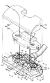
図4は、本発明の実施例に係る吸入ブラシ組立体を示す分解斜視図である。図4を参照するに、本発明の実施例に係る吸入ブラシ組立体は、カバー122、カバー122に結合され、下部には吸入口136が形成されたボディ130、ボディ130上に回転可能に設けられるタービンファン190、タービンファン190の前方に位置するようにボディ130に設けられる流路形成部材150、ボディ130に回転可能に設けられ、タービンファン190から動力を伝達されて回転する回転体180、タービンファン190から発生する動力を回転体180に伝達する動力伝達手段170とを備えてなる。
FIG. 4 is an exploded perspective view showing the suction brush assembly according to the embodiment of the present invention. Referring to FIG. 4, a suction brush assembly according to an embodiment of the present invention is connected to a
カバー122は、回転体180およびタービンファン190を覆うことができるようにボディ130に結合される第1のカバー124と、第1のカバー124の上部に位置し、ボディ130と結合される第2のカバー126とを有する。第1のカバー124が直接回転体180およびタービンファン190を覆うと共に第1のカバー124の上部を第2のカバー126が覆うことでタービンファン190と回転体180から発生する騒音が第1および第2のカバー124、126を介して外部に放出されるのを低減することができる。また、第1および第2のカバー124、126には、それぞれ外部空気が吸入されるように第1および第2の開口127、128が形成される。
The
ボディ130には、回転体180が収納される回転体収納室138が形成され、回転体収納室138には、回転体180が取り付けられる回転体取付ボス140が設けられる。回転体180は、回転体取付ボス140に挿入され、回転可能にボディ130に取り付けられる。また、第1および第2の開口127、128を介して吸入された外部空気は、回転体収納室138に案内される。
The body 130 is formed with a rotating
タービンファン190は、ボディ130の後端部に回転可能に取り付けられる。このようなタービンファン190は、複数のタービンブレード192を有し、吸入口136から吸入される空気がタービンブレード192にぶつかってタービンファン190が回転するようになる。
The
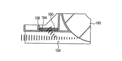
流路形成部材150は、両側にスライド溝154が形成され、このスライド溝154に対応するようにボディ130にスライド突起152が形成され、流路形成部材150を上から下へスライドさせてボディ130に取り付けるようになる。そして、流路形成部材150は、タービンファン190の前方に形成され、吸入口136に吸入された空気をタービンファン190に案内する。流路形成部材150により形成された流路は、吸入口136からだんだん狭くなる形状を有するため、吸入された空気の流速を速くする。これにより、タービンファン190は、より高い回転力を得ることができる。また、流路形成部材150の上部には、吸音材160を取り付けるための吸音材取付部156が形成され、吸音材取付部156の底面には、多数の貫通孔158が形成される。この貫通孔158は、吸入流路134(図7参照)まで貫設され、吸入流路134を介して外部に放出される騒音を減らす機能を果たす。
The flow
回転体180は、回転体収納室138に形成された回転体取付ボス140に挿入され、回転可能に取り付けられる。回転体180の下部には、掃除部材182が着脱できるように掃除部材装着部184が形成される。掃除部材182としては、雑巾などを使用することができる。このような掃除部材182は、タービンファン190から伝達される動力により回転する回転体180と共に回転しながら被掃除面上の塵埃などを拭き取る機能をする。また、このような回転体180は、回転体取付ボス140との間に結合隙間181(図5参照)を形成する。前述のような構造で、図4において矢印で示されるように、第1および第2のカバー124、126が形成された第1および第2の開口127、128を介して回転体収納室138に吸入された外部空気は、結合隙間181を介してボディ130の下部に流出される。また、ボディ130の下部に流出された外部空気は、再び吸入口136に吸入される。これにより、結合隙間181を介して回転体収納室138に塵埃などが流入されるのを防止することが可能となる。
The
動力伝達手段170は、タービンファン190により発生された動力を回転体180に伝達する機能を行う。このような動力伝達手段170は、タービンファン190の同軸上から左右に延長形成されたウォーム172と、ウォーム172に対応するように回転体180の上部に形成されたウォームホイール174とで構成される。しかし、この他にさまざまな手段によりタービンファン190から回転体180に動力を伝達することができる。
The
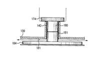
図5は、図4のV−Vに沿った断面図であって、回転体180への塵埃の流入を防止する動作を説明するための図である。図5を参照するに、第1および第2のカバー124、126(図4参照)に形成された第1および第2の開口127、128(図4参照)を介して流入された外部空気は、回転体収納室138(図4参照)に形成された真空により回転体収納室138に流入される。回転体収納室138に流入された外部空気は、回転体取付ボス140とウォームホイール174、回転体取付ボス140と回転体180、および回転体収納室138の底面板139と掃除部材装着部184との間に形成された結合隙間181を介して矢印方向のようにボディ130の下部に流出される。このような作用で、被掃除面上の塵埃がボディ130の下部から結合隙間181を介して回転体180、ウォームホイール174、ウォーム172(図4参照)に流入されるのを防止することができる。これにより、回転体180の回転が円滑に行われ、掃除の効率が向上する。
FIG. 5 is a cross-sectional view taken along the line V-V in FIG. 4 and is a view for explaining an operation for preventing the inflow of dust into the
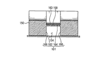
図6および図7は、図4のVI−VIおよびVII−VIIに沿った断面図であって、タービンファン190および各種の部品から発生する騒音を減らす動作を説明するための図である。図6および図7を参照するに、吸入口136(図4参照)から吸入された空気をタービンファン190まで案内する吸入流路134は、流路形成部材150に形成された流路隔壁161により形成される空間である。このような流路隔壁161は、吸入流路134の上部を形成する上部隔壁164と、吸入流路134の側部を形成する側部隔壁166と、吸入流路134の底面を形成するボディ130の底面板162とで取り囲まれている。また、上部隔壁164には、複数の貫通孔158が形成され、貫通孔158が形成された上部隔壁164の上面には吸音材160が取り付けられている。
6 and 7 are cross-sectional views taken along lines VI-VI and VII-VII in FIG. 4, and are diagrams for explaining an operation of reducing noise generated from the
タービンファン190および各種の部品から発生する騒音は、吸入流路134に沿って吸入口136から外部に伝達される。このとき、上部隔壁164に形成された複数の貫通孔158は、吸入流路134上の圧力を変化させることで、タービンファン190から発生する騒音は貫通孔158を介して吸音材160に吸収される。本実施例においては、吸音材160を設けているが、吸音材160を省略し、貫通孔158のみを形成する場合でも、タービンファン190から発生する高周波騒音が低減されることが実験で明らかになった。このような実験に関する詳細な説明は、後述する。また、貫通孔158は、上部隔壁164の他に側部隔壁166またはボディ130の底面板162に形成されることもできる。
Noise generated from the
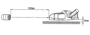
図8は、吸入ブラシ組立体から発生する高周波騒音の低減効果を確認するための実験条件を示す概念図であり、図9は、図8の実験条件で計測されたデータによるグラフである。図8を参照するに、先ず、吸入ブラシ組立体を被掃除面から100mm離間して真空掃除機を稼動させ、吸入ブラシ組立体から1000mmの距離で音圧を計測した。また、実験サンプルとしては、(イ)貫通孔158が形成されていない吸入ブラシ組立体(以下、「C」と記する)。(ロ)上部隔壁164に複数の貫通孔158が形成された吸入ブラシ組立体(以下、「R1」と記する)、(ハ)上部隔壁164に複数の貫通孔158を形成し、上部隔壁164の上面に吸音材160を設けた吸入ブラシ組立体(以下、「R2」と記する)を使用した。また、貫通孔158の径は、2.3mmであり、貫通孔158の個数は、30個である。
FIG. 8 is a conceptual diagram showing experimental conditions for confirming the effect of reducing high-frequency noise generated from the suction brush assembly, and FIG. 9 is a graph based on data measured under the experimental conditions of FIG. Referring to FIG. 8, first, the vacuum brush was operated with the
図9を参照するに、横軸は、吸入ブラシ組立体から発生する騒音の周波数を示し、縦軸は、前記周波数による音圧を示す。それぞれの単位は、HzおよびdBである。 Referring to FIG. 9, the horizontal axis represents the frequency of noise generated from the suction brush assembly, and the vertical axis represents the sound pressure due to the frequency. Each unit is Hz and dB.
実験の結果を次の表1に示す。 The results of the experiment are shown in Table 1 below.

また、前記表中の全体騒音は、図9に示された周波数の全体範囲を積分した値であって、貫通孔158のみが形成された吸入ブラシ組立体(R1)の場合に3dB程度低減し、吸音材160が取り付けられた場合に低減効果が一層向上した。
The total noise in the table is a value obtained by integrating the entire frequency range shown in FIG. 9, and is reduced by about 3 dB in the case of the suction brush assembly (R1) in which only the through
結局、吸入流路134上に貫通孔158を形成することで、吸入ブラシ組立体の騒音が減少し、また、吸音材160を適用すると、低減効果は、一層向上することがわかる。また、実験結果のように使用者の敏感な反応を引き起こす高周波騒音、特に高周波におけるピーク騒音は、一層減少することがわかる。
Eventually, by forming the through-
本発明は、真空掃除機の吸入ブラシ組立体に関し、特に、掃除効率を向上させると共に騒音を低減することができるように構造が改善された吸入ブラシ組立体およびこれを備えた真空掃除機に関するものであって、本発明は、キャニスタータイプの掃除機だけでなく、アップライトタイプの真空掃除機にも適用可能である。また、本発明は、家庭用掃除機は言うまでもなく産業用掃除機にも適用可能である。 The present invention relates to a suction brush assembly of a vacuum cleaner, and more particularly to a suction brush assembly having an improved structure so as to improve cleaning efficiency and reduce noise, and a vacuum cleaner including the same. The present invention is applicable not only to canister type vacuum cleaners but also to upright type vacuum cleaners. Further, the present invention can be applied to an industrial vacuum cleaner as well as a household vacuum cleaner.
122 カバー
124、126 第1および第2のカバー
127、128 第1および第2の開口
130 ボディ
134 吸入流路
136 吸入口
150 流路形成部材
156 吸音材取付部
158 貫通孔
160 吸音材
161 流路隔壁
162 ボディ底面板
164 上部隔壁
166 側部隔壁
170 動力伝達手段
172 ウォーム
174 ウォームホイール
180 回転体
181 結合隙間
182 掃除部材
184 掃除部材装着部
190 タービンファン
122
Claims (9)
前記ボディに結合され、外部空気が吸入されるように開口が形成されたカバーと、
前記ボディに回転可能に設けられ、下部に被掃除面と接触する掃除部材が着脱可能に装着される回転体とを含み、
前記開口から吸入された外部空気が前記回転体と前記ボディとの間に形成された結合隙間を通過して前記ボディの下部に流出されることを特徴とする吸入ブラシ組立体。 A body formed with an inlet for inhaling dust on the surface to be cleaned;
A cover coupled to the body and having an opening formed to allow external air to be sucked;
A rotating body that is rotatably provided on the body and on which a cleaning member that comes into contact with the surface to be cleaned is detachably mounted;
The suction brush assembly, wherein the external air sucked from the opening passes through a coupling gap formed between the rotating body and the body and flows out to a lower portion of the body.
前記タービンファンに連結され、前記回転体に動力を伝達する動力伝達手段とを更に含むことを特徴とする請求項1に記載の吸入ブラシ組立体。 A turbine fan rotatably provided on the body;
The suction brush assembly according to claim 1, further comprising power transmission means coupled to the turbine fan and transmitting power to the rotating body.
前記ボディに結合されるカバーと、
前記ボディに回転可能に設けられたタービンファンと、
前記吸入口から吸入された空気を前記タービンファンに案内する吸入流路と、
前記吸入流路を形成し、複数の貫通孔が形成された流路隔壁とを含むことを特徴とする吸入ブラシ組立体。 A body formed with an inlet for inhaling dust on the surface to be cleaned;
A cover coupled to the body;
A turbine fan rotatably provided on the body;
A suction flow path for guiding air sucked from the suction port to the turbine fan;
A suction brush assembly, comprising: a suction channel, and a partition wall formed with a plurality of through holes.
前記吸入力発生部と空気流動可能に前記真空掃除機本体に連結される延長流路と、
前記延長流路に連結され、被掃除面上の塵埃などを吸入する吸入ブラシ組立体とを備え、
前記吸入ブラシ組立体は、
被掃除面上の塵埃などを吸入する吸入口が形成されたボディと、前記ボディに結合されるカバーと、前記ボディに回転可能に設けられたタービンファンと、前記吸入口から吸入された空気を前記タービンファンに案内する吸入流路と、前記吸入流路を形成し、複数の貫通孔が形成された流路隔壁とを備えることを特徴とする真空掃除機。 A vacuum cleaner body with a built-in suction input generator,
An extension passage connected to the vacuum cleaner main body so as to allow air flow with the suction input generating portion;
A suction brush assembly connected to the extension flow path and sucking dust and the like on the surface to be cleaned;
The suction brush assembly includes:
A body formed with a suction port for sucking dust and the like on the surface to be cleaned, a cover coupled to the body, a turbine fan rotatably provided on the body, and air sucked from the suction port A vacuum cleaner comprising: a suction channel that guides the turbine fan; and a channel partition that forms the suction channel and has a plurality of through holes.
Applications Claiming Priority (2)
| Application Number | Priority Date | Filing Date | Title |
|---|---|---|---|
| KR20040025183 | 2004-04-13 | ||
| KR1020040057754A KR100582517B1 (en) | 2004-04-13 | 2004-07-23 | A suction brush assembly and a vacuum cleaner having the same |
Publications (1)
| Publication Number | Publication Date |
|---|---|
| JP2005296621A true JP2005296621A (en) | 2005-10-27 |
Family
ID=36219332
Family Applications (1)
| Application Number | Title | Priority Date | Filing Date |
|---|---|---|---|
| JP2004334974A Pending JP2005296621A (en) | 2004-04-13 | 2004-11-18 | Suction brush assembly and vacuum cleaner provided with the same |
Country Status (9)
| Country | Link |
|---|---|
| US (1) | US7334291B2 (en) |
| JP (1) | JP2005296621A (en) |
| CN (1) | CN1325009C (en) |
| AU (1) | AU2005200611B2 (en) |
| DE (1) | DE102005008472A1 (en) |
| FR (1) | FR2868681B1 (en) |
| GB (1) | GB2413062B (en) |
| NL (1) | NL1028419C2 (en) |
| RU (1) | RU2286077C2 (en) |
Cited By (8)
| Publication number | Priority date | Publication date | Assignee | Title |
|---|---|---|---|---|
| JP2013146303A (en) * | 2012-01-17 | 2013-08-01 | Sharp Corp | Self-propelled vacuum cleaner |
| JP2016013474A (en) * | 2015-09-24 | 2016-01-28 | シャープ株式会社 | Self-propelled vacuum cleaner |
| JP2016026857A (en) * | 2015-11-17 | 2016-02-18 | シャープ株式会社 | Self-propelled vacuum cleaner |
| JP2016026856A (en) * | 2015-11-17 | 2016-02-18 | シャープ株式会社 | Self-propelled cleaner |
| JP2016026854A (en) * | 2015-11-17 | 2016-02-18 | シャープ株式会社 | Self-propelled vacuum cleaner |
| JP2016026855A (en) * | 2015-11-17 | 2016-02-18 | シャープ株式会社 | Self-propelled vacuum cleaner |
| JP2016039993A (en) * | 2015-11-17 | 2016-03-24 | シャープ株式会社 | Self-propelled vacuum cleaner |
| JP2016039994A (en) * | 2015-11-17 | 2016-03-24 | シャープ株式会社 | Self-propelled vacuum cleaner |
Families Citing this family (20)
| Publication number | Priority date | Publication date | Assignee | Title |
|---|---|---|---|---|
| KR100592095B1 (en) * | 2004-11-03 | 2006-06-22 | 삼성광주전자 주식회사 | Suction structure assembly of vacuum cleaner |
| KR100718283B1 (en) * | 2006-01-11 | 2007-05-16 | 삼성광주전자 주식회사 | Suction brush for vacuum cleaner |
| KR101408733B1 (en) * | 2007-05-15 | 2014-06-19 | 삼성전자주식회사 | Suction brush for steam-powered vacuum cleaner |
| CA2684168A1 (en) * | 2009-10-30 | 2011-04-30 | G.B.D. Corp. | Surface cleaning head |
| US9072415B2 (en) | 2010-11-05 | 2015-07-07 | Bissell Homecare, Inc. | Bare floor vacuum cleaner |
| US9801513B2 (en) * | 2011-11-24 | 2017-10-31 | Omachron Intellectual Property Inc. | Turbo brush |
| ITUD20130115A1 (en) * | 2013-09-03 | 2015-03-04 | Longhi Appliances S R L Con Un Ico Socio De | BRUSH FOR CLEANING EQUIPMENT |
| GB2529820B (en) * | 2014-09-02 | 2016-10-26 | Dyson Technology Ltd | Cleaner head |
| CN106955057B (en) * | 2017-05-17 | 2019-09-06 | 江苏美的清洁电器股份有限公司 | Control unit and floor brush of dust collector |
| KR102679309B1 (en) | 2018-04-30 | 2024-07-01 | 엘지전자 주식회사 | Nozzle for cleaner |
| CN115989982B (en) | 2018-04-30 | 2026-01-16 | Lg电子株式会社 | Suction nozzle of cleaner |
| WO2019212177A1 (en) | 2018-04-30 | 2019-11-07 | 엘지전자 주식회사 | Cleaner nozzle |
| CN114869170B (en) | 2018-04-30 | 2024-04-12 | Lg电子株式会社 | Cleaner |
| WO2019212195A1 (en) * | 2018-04-30 | 2019-11-07 | 엘지전자 주식회사 | Vacuum cleaner nozzle |
| WO2019212176A1 (en) | 2018-04-30 | 2019-11-07 | 엘지전자 주식회사 | Cleaner nozzle |
| KR102711296B1 (en) | 2018-04-30 | 2024-09-30 | 엘지전자 주식회사 | Nozzle for cleaner |
| KR102625905B1 (en) | 2018-07-30 | 2024-01-18 | 엘지전자 주식회사 | Nozzle for cleaner |
| US11998150B2 (en) * | 2019-05-01 | 2024-06-04 | Sharkninja Operating Llc | Vacuum cleaner and docking station for use with the same |
| USD950176S1 (en) * | 2020-02-27 | 2022-04-26 | Lg Electronics Inc. | Nozzle for vacuum cleaner |
| CN112890677B (en) * | 2021-03-26 | 2022-03-08 | 西安医学院第二附属医院 | Medical bed sweeping device |
Family Cites Families (23)
| Publication number | Priority date | Publication date | Assignee | Title |
|---|---|---|---|---|
| JPS5128363A (en) * | 1974-09-04 | 1976-03-10 | Yasue Tanaka | SOJIKI |
| JPS57200120A (en) * | 1981-06-03 | 1982-12-08 | Hitachi Ltd | Upright type electric cleaner |
| JPS6185911A (en) | 1984-10-02 | 1986-05-01 | 株式会社東芝 | Cleaner |
| JPS6187517A (en) * | 1984-10-08 | 1986-05-02 | 松下電器産業株式会社 | vacuum cleaner floor nozzle |
| JPS6458224A (en) | 1987-08-28 | 1989-03-06 | Matsushita Electric Industrial Co Ltd | Floor nozzle for cleaner |
| SU1736423A1 (en) * | 1990-04-23 | 1992-05-30 | В.Д. Нагорных | Vacuum cleaner jet |
| AU8514591A (en) * | 1990-08-08 | 1992-03-17 | Arthur L. Fassauer | Air-floated apparatus |
| JP2520375B2 (en) | 1993-05-29 | 1996-07-31 | 大宇電子株式會▲社▼ | Brush assembly for vacuum cleaner with sound absorber |
| KR0129653Y1 (en) * | 1993-09-17 | 1999-10-01 | 김광호 | Suction brush of vacuum cleaner |
| JPH0928632A (en) | 1995-07-14 | 1997-02-04 | Hitachi Ltd | Electric vacuum cleaner |
| KR0136306Y1 (en) | 1996-09-10 | 1999-02-01 | 최진호 | Suction nozzle of a vacuum cleaner |
| CN1188634A (en) | 1996-09-10 | 1998-07-29 | 光州电子株式会社 | Getter device of vacuum cleaner |
| KR19980023805A (en) * | 1996-09-30 | 1998-07-06 | 배순훈 | Brush Drive for Vacuum Cleaner |
| KR100208133B1 (en) * | 1997-06-25 | 1999-07-15 | 최진호 | Suction device of vacuum cleaner |
| KR100208134B1 (en) * | 1997-06-25 | 1999-07-15 | 최진호 | Suction device of vacuum cleaner |
| JP2823013B2 (en) * | 1997-11-21 | 1998-11-11 | 株式会社日立製作所 | Vacuum cleaner and its suction body |
| JP2000060773A (en) * | 1998-08-19 | 2000-02-29 | Kenichi Nagai | Vacuum cleaner |
| KR100282337B1 (en) * | 1998-09-01 | 2001-02-15 | 구자홍 | Suction port for vacuum cleaner |
| US6792648B2 (en) * | 2000-03-28 | 2004-09-21 | Samsung Kwangju Electronics Co., Ltd. | Floor cloth for use in vacuum cleaner and apparatus of vacuum cleaner for rotatably driving the floor cloth |
| AU779644B2 (en) * | 2000-10-31 | 2005-02-03 | Samsung Gwangju Electronics Co., Ltd. | Suction port assembly of vacuum cleaner |
| KR100420170B1 (en) | 2001-08-21 | 2004-03-02 | 삼성광주전자 주식회사 | Brush of vacuum cleaner having floor cloth |
| KR100470559B1 (en) * | 2002-05-11 | 2005-03-08 | 삼성광주전자 주식회사 | Sucking device of a vacuum cleaner |
| KR20030093625A (en) | 2002-06-04 | 2003-12-11 | 삼성광주전자 주식회사 | A Brush of vacuum cleaner with floor cloth using a Turbine |
-
2004
- 2004-11-18 JP JP2004334974A patent/JP2005296621A/en active Pending
- 2004-12-15 US US11/013,024 patent/US7334291B2/en not_active Expired - Lifetime
-
2005
- 2005-02-02 CN CNB2005100062969A patent/CN1325009C/en not_active Expired - Fee Related
- 2005-02-11 AU AU2005200611A patent/AU2005200611B2/en not_active Expired
- 2005-02-15 RU RU2005104021/12A patent/RU2286077C2/en not_active IP Right Cessation
- 2005-02-24 DE DE102005008472A patent/DE102005008472A1/en not_active Withdrawn
- 2005-02-25 NL NL1028419A patent/NL1028419C2/en not_active IP Right Cessation
- 2005-02-25 GB GB0503943A patent/GB2413062B/en not_active Expired - Fee Related
- 2005-02-25 FR FR0501932A patent/FR2868681B1/en not_active Expired - Fee Related
Cited By (8)
| Publication number | Priority date | Publication date | Assignee | Title |
|---|---|---|---|---|
| JP2013146303A (en) * | 2012-01-17 | 2013-08-01 | Sharp Corp | Self-propelled vacuum cleaner |
| JP2016013474A (en) * | 2015-09-24 | 2016-01-28 | シャープ株式会社 | Self-propelled vacuum cleaner |
| JP2016026857A (en) * | 2015-11-17 | 2016-02-18 | シャープ株式会社 | Self-propelled vacuum cleaner |
| JP2016026856A (en) * | 2015-11-17 | 2016-02-18 | シャープ株式会社 | Self-propelled cleaner |
| JP2016026854A (en) * | 2015-11-17 | 2016-02-18 | シャープ株式会社 | Self-propelled vacuum cleaner |
| JP2016026855A (en) * | 2015-11-17 | 2016-02-18 | シャープ株式会社 | Self-propelled vacuum cleaner |
| JP2016039993A (en) * | 2015-11-17 | 2016-03-24 | シャープ株式会社 | Self-propelled vacuum cleaner |
| JP2016039994A (en) * | 2015-11-17 | 2016-03-24 | シャープ株式会社 | Self-propelled vacuum cleaner |
Also Published As
| Publication number | Publication date |
|---|---|
| GB2413062B (en) | 2006-05-10 |
| CN1325009C (en) | 2007-07-11 |
| GB0503943D0 (en) | 2005-04-06 |
| GB2413062A (en) | 2005-10-19 |
| US7334291B2 (en) | 2008-02-26 |
| CN1682631A (en) | 2005-10-19 |
| NL1028419A1 (en) | 2005-10-17 |
| US20050223522A1 (en) | 2005-10-13 |
| FR2868681A1 (en) | 2005-10-14 |
| AU2005200611B2 (en) | 2007-04-19 |
| AU2005200611A1 (en) | 2005-10-27 |
| NL1028419C2 (en) | 2006-02-21 |
| RU2005104021A (en) | 2006-07-20 |
| DE102005008472A1 (en) | 2005-11-10 |
| RU2286077C2 (en) | 2006-10-27 |
| FR2868681B1 (en) | 2010-01-01 |
Similar Documents
| Publication | Publication Date | Title |
|---|---|---|
| JP2005296621A (en) | Suction brush assembly and vacuum cleaner provided with the same | |
| JP2009050687A (en) | Stick type vacuum cleaner | |
| JP2006015113A (en) | Suction port assembly and vacuum cleaner provided with the same | |
| KR100809738B1 (en) | Vacuum cleaner | |
| US20060185119A1 (en) | Brush assembly for a vacuum cleaner | |
| KR20060122521A (en) | Vacuum cleaner | |
| CN101204303A (en) | vacuum cleaner nozzle | |
| KR20040036182A (en) | Suction nozzle for vacuum cleaner | |
| CN101242768A (en) | Discharge Structure of Vacuum Cleaners | |
| KR100582517B1 (en) | A suction brush assembly and a vacuum cleaner having the same | |
| JP5909635B2 (en) | Electric vacuum cleaner | |
| KR100631571B1 (en) | Suction head of vacuum cleaner | |
| CN217539120U (en) | Surface cleaning machine that noise reduction effect is good | |
| KR20040050217A (en) | suction assembly for vacuum cleaner | |
| JP5819687B2 (en) | Vacuum cleaner suction port | |
| KR101055076B1 (en) | Nozzle of vacuum cleaner | |
| JP2013034592A (en) | Vacuum cleaner | |
| CN202739918U (en) | Vertical type electric dust collector | |
| KR100710392B1 (en) | Vacuum cleaner | |
| CN100531647C (en) | vacuum cleaner suction head | |
| JP2011019820A (en) | Vacuum cleaner | |
| KR101246483B1 (en) | Suction nozzle of vaccum cleaner | |
| KR100240762B1 (en) | Neck structure of suction brush for vacuum cleaner | |
| KR20240020600A (en) | Vacuum cleaner | |
| KR200328541Y1 (en) | Nozzle for cleaner |
Legal Events
| Date | Code | Title | Description |
|---|---|---|---|
| A131 | Notification of reasons for refusal |
Free format text: JAPANESE INTERMEDIATE CODE: A131 Effective date: 20070814 |
|
| A601 | Written request for extension of time |
Free format text: JAPANESE INTERMEDIATE CODE: A601 Effective date: 20071106 |
|
| A602 | Written permission of extension of time |
Free format text: JAPANESE INTERMEDIATE CODE: A602 Effective date: 20071109 |
|
| A02 | Decision of refusal |
Free format text: JAPANESE INTERMEDIATE CODE: A02 Effective date: 20080226 |