JP2005296591A - card case - Google Patents
card case Download PDFInfo
- Publication number
- JP2005296591A JP2005296591A JP2004148416A JP2004148416A JP2005296591A JP 2005296591 A JP2005296591 A JP 2005296591A JP 2004148416 A JP2004148416 A JP 2004148416A JP 2004148416 A JP2004148416 A JP 2004148416A JP 2005296591 A JP2005296591 A JP 2005296591A
- Authority
- JP
- Japan
- Prior art keywords
- card
- packaging material
- outer packaging
- storage chamber
- card storage
- Prior art date
- Legal status (The legal status is an assumption and is not a legal conclusion. Google has not performed a legal analysis and makes no representation as to the accuracy of the status listed.)
- Granted
Links
Images

Landscapes
- Sheet Holders (AREA)
- Purses, Travelling Bags, Baskets, Or Suitcases (AREA)
Abstract
【課題】 一室ずつ仕切られたカード収納室に多数のカードが一枚ずつ収納可能で、且つカードの出し入れや識別が容易に可能なカードケースを提供する。更には前記主課題を解決すると共にカードケースを開いた状態で傾斜等をしもカードが脱落しにくいカードケースを提供する。更には手入れが容易に可能で、且つコンパクトで、携帯に便利なカードケースを提供する。
【解決手段】 外包材の内部に、襞部材の屈曲部に相当する部位が糸で縫着され、且つカード出し入れ時における外包材の開閉でカード収納室の幅が変化し、上部の出し入れ口や底部が開口した六角形のカード収納室を一個備えたカード収納襞を複数備えた事を特徴とするカードケース。
【効果】 前記課題が解決された。
【選択図】 図1。PROBLEM TO BE SOLVED: To provide a card case in which a large number of cards can be stored one by one in a card storing room partitioned by one room, and the cards can be easily inserted and removed. Furthermore, the present invention provides a card case that solves the above-mentioned main problems and prevents the card from dropping off even if the card case is tilted and the like is opened. Furthermore, the present invention provides a card case that can be easily maintained and is compact and convenient to carry.
A portion corresponding to a bent portion of the collar member is sewn with a thread inside the outer packaging material, and the width of the card storage chamber is changed by opening / closing the outer packaging material when the card is inserted / removed. A card case comprising a plurality of card storage baskets each having a hexagonal card storage chamber with an open bottom.
[Effect] The above problem has been solved.
[Selection] FIG.
Description
本発明はカードケースに関する。更に詳しくは各種多数のカードを一個のケースに一枚ずつ各別に収納でき、しかもカード出し入れ時に外包材を開くとカード収納室の幅が大になり、カードが立体的に立ち上がり、カードの出し入れや識別等容易に出来、コンパクトなカードケースに関する。更にはカードが脱落しにくいカードケースに関する。更には紙幣や他の小物類等を収納可能な補助収納室を外包材や内部に備え、且つ携帯に便利でコンパクトなカードケースに関する。 The present invention relates to a card case. More specifically, a large number of various cards can be stored separately in each case, and when the outer packaging material is opened when inserting and removing the card, the width of the card storage room increases, the card rises in three dimensions, It relates to a compact card case that can be easily identified. Further, the present invention relates to a card case in which the card is difficult to drop off. Further, the present invention relates to a compact card case that is provided with an auxiliary storage chamber capable of storing banknotes, other small items, and the like inside and outside and is convenient to carry.
金融機関や他のサービス機関等が発行した多数のカードが使用されている。従来カードケースとしてカード収納室を備えた財布が使用されていた。このような財布として、特許文献1に一方の内面に紙幣収納室を備え他方の内面に段状に形成されたカード収納室を備えた財布が開示されている。
又特許文献2や3等に内面の両側に段状に形成されたカード収納室を備えた財布が開示されている。
前記3件に開示された技術にあつては、ある小量のカードは収納可能かもしれないが、多数のカードをそれぞれの収納室に一枚ずつ収納する事は不可能である。前記技術において多数のカードを収納する場合、カード収納室一室に複数のカードを重ねて収納する必要があり必然的にカードの識別や出し入れ等が困難となる。又一室に一枚ずつ収納する場合、多数の収納室を備える必要があり、大型の財布となる。従ってコンパクト性に劣る物となる。Many cards issued by financial institutions and other service institutions are used. Conventionally, a wallet provided with a card storage room has been used as a card case. As such a wallet, Patent Document 1 discloses a wallet including a banknote storage chamber on one inner surface and a card storage chamber formed in a step shape on the other inner surface.
With the technologies disclosed in the three cases, a small amount of cards may be stored, but it is impossible to store a large number of cards one by one in each storage chamber. In the case of storing a large number of cards in the above technique, it is necessary to store a plurality of cards in a single card storage chamber, which inevitably makes it difficult to identify and remove cards. Moreover, when storing one by one in a room, it is necessary to provide a large number of storage rooms, which makes a large wallet. Therefore, it becomes a thing inferior to compactness.
特許文献4にカバー材の内部に、合成樹脂シート等が山谷折りされ収納室が蛇腹状に形成された小物収容具が開示されている。又特許文献5にカバー本体の内部に交互に複数個所折り曲げた蛇腹体を一端側面から二つ折りにし、折返し面を接着した扇状の蛇腹体を備えたカードケースが開示されている。
前記2件に開示された技術にあつては収納室が蛇腹体に形成されているので、本体の開閉により収納物が立体的に立ち上がるという機能がある。
Since the storage chamber is formed in the bellows body in the technologies disclosed in the above two cases, there is a function that the storage object rises in three dimensions by opening and closing the main body.
しかし前記特許文献4に開示された技術にあつては、一枚物の基材を突出片を有する特殊構造に打ち抜き、V状の波型に折り曲げ谷と山を交互に形成し、突出片を外側に折り曲げ本体部を外側から支え、夫々の収容部を形成した物である。この技術にあつては夫々の収容部は突出片で支えているのみであり縫着等がされていない。従つて各収容部が襞部で外れ易い。又各収容部はその底部が閉塞し一室を構成している。従つてその底部に異物等が堆積し易く、該異物等により、カードを損傷する事があつた。また手入れする場合すべての収容物を抜き取って手入れする必要があつた。更に底部が閉塞しているので、小物収容具を開いた時カードはその底部の縁部が接しているのみで、カードの底部近傍の面が挟持されていない。従つて小物収容具を開きその出し入れ口を下方に傾斜した場合、カードが脱落するという課題がある。又屈曲部が湾曲した構造であり、長期使用により屈曲部が更に変形し易いという課題がある。 However, in the technique disclosed in
又前記特許文献5に開示されたカードケースの場合、夫々の収納室は側面の仕切りがなく、蛇腹体の対面する略V状に形成された空間部の両端にカードの両端のみ挟み込んで収納するように構成されている。従つてカードを収納する場合、カードが正しい収納室に収納されず、隣接する他の収納室にカードの一方の端部が入り込んだ状態で収納される事がある。従つてカードケースやカード等が損傷し易い。又各収納室の底部は閉塞し夫々の収納室を構成している。従つてその底部に異物等が堆積し易い。従つてすべてのカードをぬきとつて掃除する必要があつた。更に底部が閉塞しているので、カードケースを開いた時カードはその底部の縁部が接しているのみで、カードの底部近傍の側面が挟持されていない。従つてカードケースを開きその出し入れ口を下方に傾斜した場合、カードが脱落するという課題がある。 Further, in the case of the card case disclosed in
又前記特許文献4や5等に開示された技術には、収容部や蛇腹体の底部とカバー等の間が閉塞された構造となつている。従つて該空間部に略棒状の小物等を収納出来ない。
本発明は前記背景技術の課題を解決するために為されたものであり、一個のケースに多数のカードを一枚ずつ各別に収納可能で、カードケースを開くと隣接するカード間の幅が大となりカードが立体的に立ち上がり、カードの出し入れや識別等が容易なカードケースを提供するものである。又カード以外の他の書類や紙幣等も収納可能なカードケースを提供するものである。又カード出し入れ時にカドケースを下方に傾斜してもカードが脱落しにくいカードケースを提供するものである。又カードケースの手入れが容易で、その底部に棒状の小物等が収納可能で、かつコンパクトなカードケースを提供するものである。 The present invention has been made in order to solve the above-described problems of the background art, and can store a large number of cards one by one in one case. When the card case is opened, the width between adjacent cards is large. The card case rises three-dimensionally, and provides a card case that allows easy card insertion / removal and identification. The present invention also provides a card case that can store documents other than cards, banknotes, and the like. It is another object of the present invention to provide a card case in which the card is not easily dropped even when the card case is inclined downward when the card is inserted or removed. Further, the present invention provides a compact card case that can be easily cared for, can store a rod-shaped accessory at the bottom, and the like.
本発明は前記課題を解決するため、カード収納室、外包材等の構成や使用する材料等を鋭意研究し成されたものであり、以下に示すようなカードケースを提供するものである。 In order to solve the above-mentioned problems, the present invention has been made by intensive research on the configuration of the card storage room, the outer packaging material, etc., the materials used, and the like, and provides a card case as shown below.
(1)留め具を備えた外包材を備えその内部に、襞部材の屈曲部が糸で縫着され且つ外包材の開閉でカード収納室の幅が変化し、出し入れ口及び底部が開口した六角形のカード収納室を一室備えたカード収納襞を、複数個備えた事を特徴とするカードケース。(1) An outer packaging material provided with a fastener is provided, in which the bent portion of the collar member is sewn with a thread, and the width of the card storage chamber is changed by opening and closing the outer packaging material, and the slot and the bottom are opened. A card case characterized by having a plurality of card storage boxes each having a square card storage room.
(2)カード収納襞は、その側面が外包材に糸で縫着された請求項1に記載のカードケース。(2) The card case according to claim 1, wherein a side surface of the card storage case is sewn to the outer packaging material with a thread.
(3)カード収納襞は、その底部と外包材の底部との間に5から20mmの空隙を有するように外包材の内部に配置された請求項1又は2に記載のカードケース。(3) The card case according to claim 1 or 2, wherein the card storage case is disposed inside the outer packaging material so as to have a gap of 5 to 20 mm between the bottom portion and the bottom portion of the outer packaging material.
(4)外包材は、折り曲げ部に線状のプレス線を有する芯材の表面側に表面布帛が接合された表面部材を備え、更にその内面に内面布帛が接合されたものである請求項1から3いずれかに記載のカードケース。(4) The outer packaging material includes a surface member in which a surface fabric is bonded to the surface side of a core material having a linear press line at a bent portion, and an inner surface fabric is bonded to the inner surface thereof. To card case in any one of 3.
(5)補助収納室を備えた請求項1から4いずれかに記載のカードケース。(5) The card case according to any one of claims 1 to 4, further comprising an auxiliary storage chamber.
(6)襞部材は硬さ指数40以下の繊維布帛である請求項1から5いずれかに記載のカードケース。(6) The card case according to any one of claims 1 to 5, wherein the heel member is a fiber fabric having a hardness index of 40 or less.
(7)襞部材は縫着部の端部に切欠部を有しかつ折り曲げられたものである請求項1から6いずれかに記載のカードケース。(7) The card case according to any one of claims 1 to 6, wherein the collar member has a notch at the end of the sewn portion and is bent.
(8)外包材は表面側にクレープ加工された布が接合されたものである請求項1から7いずれかに記載のカードケース。(8) The card case according to any one of claims 1 to 7, wherein the outer packaging material is obtained by bonding a creped cloth to the surface side.
(9)留め具がチヤツクである請求項1から8いずれかに記載のカードケース。(9) The card case according to any one of claims 1 to 8, wherein the fastener is a chuck.
(10)カード収納室は密着したときの長さが50から65mmで深さが45から65mmであり、カードケースは厚みが3から40mmで幅及び長さが70から120mmである請求項1から9いずれかに記載のカードケース。(10) The card storage chamber has a length of 50 to 65 mm and a depth of 45 to 65 mm when in close contact, and the card case has a thickness of 3 to 40 mm and a width and length of 70 to 120 mm. 9. A card case according to any one of the above.
本発明の前記(1)の構成によればカード収納室を備えたカード収納襞が多数配置されているので多数のカードがコンパクトに収納可能である。又カード収納室が六角形でしかもカード出し入れ時、外包材の開閉等によりその幅が密着状態から広幅状態まで変化するように構成されているので、外包材等を開くと隣接する全てのカード間が大になりカードが立体的に立ち上がる。従つてカードの出し入れがし易くなると共に、カードの識別が容易である。又外包材を開くとカード収納室の幅が広幅状態になると同時に長さが小となるので、収納されたカードが挟み込まれるようになる。又カード収納室の底部が開口しその上部と連通している。従つてカードはその底部でその側面も挟みこまれれ、出し入れ時、カードの脱落等を阻止できる。又襞部材の屈曲部が糸で縫着され、六角形となつているので屈曲部が常にシャープで、長期間使用可能である。 According to the configuration of (1) of the present invention, since a large number of card storage troughs having a card storage chamber are arranged, a large number of cards can be stored compactly. Also, the card storage chamber is hexagonal, and when the card is inserted or removed, its width changes from the close contact state to the wide state by opening and closing the outer cover material, etc. Becomes larger and the card stands up in three dimensions. Accordingly, the card can be easily inserted and removed, and the card can be easily identified. When the outer packaging material is opened, the width of the card storage chamber becomes wide and the length is reduced at the same time, so that the stored card is sandwiched. The bottom of the card storage chamber is open and communicates with the top. Therefore, the side of the card is also sandwiched at the bottom of the card, and the card can be prevented from dropping off when being put in and out. In addition, the bent portion of the collar member is sewn with a thread to form a hexagon, so that the bent portion is always sharp and can be used for a long time.
前記(2)の構成によれば、カード収納襞の側面が外包材に縫着されているので、カード出し入れ時における外材の開閉のみで、カード収納室の幅が密着状態から広幅状態まで変化し、好ましくカードの出し入れや識別が出来る。又糸による縫着であるので接合が強い。従つて接合部の剥離等が起きず長期間使用可能である。 According to the configuration of (2), since the side surface of the card storage case is sewn to the outer packaging material, the width of the card storage chamber changes from the close contact state to the wide state only by opening and closing the outer member when the card is inserted and removed. The card can be taken in and out and identified. In addition, since it is sewn with thread, the joint is strong. Therefore, it is possible to use for a long time without peeling of the joint portion.
前記(3)の構成によれば、カード収納襞の底部と外包材の内側の底部との間に空隙が配置されている事、及びカード収納室は出し入れ口とその底部が連通し共に開口している事等により、カード収納室の底部に異物等が堆積しない構造となつている。従つて異物等によるカードの損傷を阻止できる。又異物等が外包材の底部に堆積するので、異物の確認が容易でありカードを収納した状態でその底部から簡単に異物等の除去が可能である。又カードはその底部近傍の側面がカード収納室の底部の開口部に挟みこまれるように収納される事、及び外包材を開いた時カード収納室の長さが小となりカードの両方の縁部がカード収納室の屈曲部で挟みこまれるように収納されるのでカードの出し入れ時、カードケースを開いた状態で下方に傾斜してもカードが脱落しにくい。更に又その底部の空隙部に筆記用具等の棒状の小物を収納できる。 According to the configuration of the above (3), the gap is disposed between the bottom of the card storage case and the inner bottom of the outer packaging material, and the card storage chamber has an open / close opening that communicates with the bottom thereof. As a result, foreign matter or the like does not accumulate on the bottom of the card storage chamber. Accordingly, it is possible to prevent the card from being damaged by a foreign object or the like. In addition, since foreign matters and the like are accumulated on the bottom of the outer packaging material, the foreign matters can be easily confirmed, and the foreign matters and the like can be easily removed from the bottom in a state where the card is stored. The card is stored so that the side surface near the bottom of the card is sandwiched in the opening of the bottom of the card storage chamber, and when the outer packaging material is opened, the length of the card storage chamber is reduced and both edges of the card are stored. Is stored so as to be sandwiched between the bent portions of the card storage chamber, so that when the card is inserted or removed, the card is not easily dropped even if it is tilted downward with the card case opened. Furthermore, a rod-shaped accessory such as a writing instrument can be stored in the gap at the bottom.
前記4の構成によれば外包材の部材として、折り曲げ部に細長い線状のプレス線を有する芯材を備え、しかもこの芯材に布等の布帛が両面に接合された物が使用されている。従つて中央折り曲げ部や蓋体として機能する延設部折り曲げ部等で外包材を内側に折り曲げた時、その厚みを正確に保持できかつ確実に直線状に折り曲げる事ができる。又外包材の開閉時、開閉抵抗が小さくスムーズな開閉が可能である。又布等の布帛が接合されているので手触り等の風合いが良いものとなる。 According to the configuration of 4 above, as the outer packaging material member, a core material having a long and narrow press line at the bent portion is used, and a material such as a cloth joined to both surfaces is used. . Therefore, when the outer packaging material is folded inward by the central bent portion or the extended portion bent portion functioning as a lid, the thickness can be accurately maintained and can be reliably bent linearly. Further, when opening and closing the outer packaging material, the opening and closing resistance is small and smooth opening and closing is possible. In addition, since a cloth such as a cloth is joined, a texture such as a touch is good.
前記5の構成によれば補助収納室を備えているので、貨幣、紙幣、小物等の収納が可能である。 According to the configuration of 5, the auxiliary storage chamber is provided, so that it is possible to store money, banknotes, small items and the like.
前記6の構成によれば、襞部材として剛性のある繊維布帛が使用されている。従つてカード収納室に皺が発生する事がない。従つてカードの角部が皺等に引っかかつたりせず、出し入れがスムーズに出来る。又カード収納襞がバネ様の作用があり、外包材の開閉時に無理のないスムーズな良い開閉が可能である。 According to the configuration of 6, the rigid fiber fabric is used as the heel member. Therefore, no wrinkles occur in the card storage room. Therefore, the corners of the card do not get caught in the bag etc., and it can be inserted and removed smoothly. In addition, the card holder has a spring-like action, and can be smoothly opened and closed smoothly without opening or closing the outer packaging material.
前記7の構成によれば、襞部材はその縫着部の端部に切欠部を有し、しかも折り曲げたものである。従つてその切欠部を密着した襞部材を重ね、糸で縫着し襞部材を製造する際、直線状の縫着部即ち、カード収納室の深さ方向に直線状の屈曲部を形成する事が可能である。又縫着部に針孔が形成されるので、屈曲性が一層良い、シャープな屈曲部を形成できる。 According to the structure of said 7, a collar member has a notch part in the edge part of the sewing part, and also bend | folds. Therefore, when manufacturing the heel member by stacking the heel members closely contacting the notches and sewing them with a thread, a linear sewn portion, that is, a straight bent portion in the depth direction of the card storage chamber is formed. Is possible. Further, since a needle hole is formed in the sewn portion, a sharp bent portion with better flexibility can be formed.
前記8の構成によればクレープ加工された布が配置されているので、ザラツキ感のある良い風合いとなり、しかもカード出し入れ時、カードケースが脱落しにくい。 According to the configuration described above, since the creped cloth is arranged, the texture is good with a feeling of roughness, and the card case does not easily fall off when the card is inserted or removed.
前記9の構成によれば、皮革等の外包材をチヤツクでその底部以外の前後の側面部、及び上部等完全に留める事が可能である。即ちカード収納襞を外包材の内部に完全に収納する事が可能である。 According to the configuration of 9, the outer packaging material such as leather can be completely fastened with the chuck, such as the front and rear side portions other than the bottom portion, and the upper portion. That is, it is possible to completely store the card storage box inside the outer packaging material.
前記10の構成によれば、カード収納室やカードケース等の寸法が収納すべきカードに好ましく適合するように構成されているので、カード等を好ましく収納可能である。又携帯し易いコンパクトなカードケースとなる。 According to the
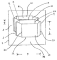
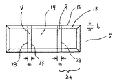
以下図面を参照しながら本発明に係るカードケースを実施するための最良の形態を説明する。図1は本発明に係るカードケースを開いたときの概略斜視図である。図2はカード収納室の概略斜視図である。図7は芯材に表面布帛が接合された表面部材の概略平面図である。図8は表面部材に内面部材が接合された外包材の概略平面図である。
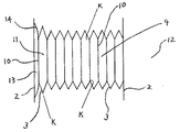
本発明の実施形態に係る図1のカードケース1は、形状保持性を有する外包材2の内部に多数のカード収納襞3を備えている。このカードケースは中央折り曲げ部Vや延設部折り曲げ部R等で折り曲げて使用するように構成されている。この折り曲げ部Vの左側内面と右側内面に挟み込まれるようにカード収納襞3を多数備えている。図1の形態ではカード収納襞を11個備えている。又カード収納襞は一個に一室のカード収納室4を備えている。The best mode for carrying out a card case according to the present invention will be described below with reference to the drawings. FIG. 1 is a schematic perspective view when the card case according to the present invention is opened. FIG. 2 is a schematic perspective view of the card storage chamber. FIG. 7 is a schematic plan view of a surface member in which a surface fabric is bonded to a core material. FIG. 8 is a schematic plan view of the outer packaging material in which the inner surface member is joined to the surface member.
The card case 1 of FIG. 1 according to the embodiment of the present invention includes a large number of
カード収納室4はカード出し入れ時における外包材の開閉等により、その屈曲部K即ち六角形となる各部位の糸による深さ方向の直線状の縫着ライン20で屈曲し、本体の開閉等により収納室の幅wが変化するように構成されている。このカード収納室4は開いたとき、上部の縁部や下部の縁部等の形状が六角形の形状をしている(図1、図2)。又カード収納室はカード出し入れ口及び下部が共に開口し連通している(図2)。
外包材2は延設部24を備えている。この延設部はカード収納襞3及び外包材の一部を包み込むような蓋体を構成している。又外包材には留め具8を備えている。この留め具は面で固着する留め具で、その一個を外包材延設部の内側に備え、他の一個を外包材の左表面側に備えている(図1)。
本発明の実施形態に係るカードケースは内面布帛17を接合した内面部材6の左右に、カード収納襞の最初の襞部材及び最後の襞部材10が、糸で縫着ライン20のように図1で示す奥側にそれぞれ二箇所ずつ縫着されている。又カード収納襞はその底部と外包材内側の底部との間に空隙Mを有するように配置されている。この縫着により、多数のカード収納襞即ちカード収納襞群12が外包材の内部に確実に備えられ、しかも外包材の開閉により全てのカード収納室が連動しその幅が変化するように構成されている。
本発明の他の実施形態に係るカードケースは、延設部のない外包材でも良い。又留め具8は、面留め具、ホツク留め具、ボタン留め具、チヤツク留め具、その他各種の留め具を用いる事ができる。又前記留め具は外包材に直接備えていても良く、他の部材を併用し外包材に接合されたものであつてもよい。他の部材を併用したものは、例えば第一の留め具を備えた帯状片を外包材に接合し、他の第二の留め具を外包材に備えた物等が例示できる。The
The
In the card case according to the embodiment of the present invention, the first heel member and the
The card case according to another embodiment of the present invention may be an outer packaging material without an extending portion. As the
外包材2は各種の材料が使用可能である。この外包材は単層構造の物、多層構造の物等いずれも使用可能である。とりわけ形状保持性を有する芯材19が外包材を構成するひとつの材料として好ましく用いられる。この芯材は例えば各種の板紙、合成樹脂板、木質板、硬質化された布、硬化剤で処理された板紙、不織布、熱融着された不織布、接着剤で接着された不織布、麻織物等が例示できる。又芯材として前記材料を二種以上併用した物が使用可能である。
外包材は前記芯材と各種布帛の併用物が使用可能である。例えば板紙を芯材とし、これに織物を重ね合わせ接合した物等が例示できる。又外包材として、板紙と不織布を重ね更に織物を表面側及び内面側に重ね、接合した物等が例示できる。又芯材として不織布と第一の板紙を配置し、表面布帛で不織布側を包み込み端部を板紙に接合し、第二の板紙に内面布帛で内面側を包み込み接合した物を更に、前記表面布帛が接合された第一の板紙に重ね接合した物等が例示できる。
又外包材として、不織布に色相や物性等の異なる他の不織布を重ね接合した物、板紙に合成樹脂フイルムを熱接着し更にその外側を織物で包み込み接合した物等、何れも使用可能である。
とりわけ外包材として、板紙、不織布、合成樹脂板等の芯材が少なくとも一個配置された物は形状保持性が良く、曲げ追従性の良さ、価格の安さ等の点で好ましく用いられる。又板紙は適度の吸湿性があるという点で好ましく用いられる。
また外包材として動物の皮革や合成皮革、マイクロフアイバー等が使用された合成皮革等も使用可能である。Various materials can be used for the
As the outer packaging material, a combination of the core material and various fabrics can be used. For example, the thing etc. which used the paperboard as the core material and overlapped and joined the textile fabric to this can be illustrated. Examples of the outer packaging material include a paperboard and a non-woven fabric, and a woven fabric that is superposed on the surface side and the inner surface side. Further, a non-woven fabric and a first paperboard are arranged as a core material, the non-woven fabric side is wrapped with a surface fabric, the end is joined to the paperboard, and the inner surface is wrapped with a second paperboard and joined to the paperboard, and the surface fabric is further joined. The thing etc. which were overlapped and joined to the 1st paperboard to which No. was joined can be illustrated.
Further, as the outer packaging material, any one can be used, such as a non-woven fabric laminated with other non-woven fabrics having different hues or physical properties, a synthetic resin film thermally bonded to paperboard, and the outside wrapped and joined with a woven fabric.
In particular, as an outer packaging material, a material in which at least one core material such as paperboard, nonwoven fabric, or synthetic resin plate is disposed is preferably used in terms of good shape retention, good bending followability, and low cost. Also, paperboard is preferably used in that it has moderate hygroscopicity.
In addition, animal leather, synthetic leather, synthetic leather using microfiber etc. can be used as the outer packaging material.
本発明の実施形態で使用する芯材19は厚みが約0・1から4mmであり、好ましくは約0・1から3mmであり、更に好ましくは約0・2から2mmである。芯材の長さや幅は外包材全体の長さや幅とほぼ同じであれば良い。又芯材は全体が一体物でカードケースの上蓋を形成する長さの延設部24を有する物が用いられる(図1、図7)。
芯材19は中央折り曲げ部V及び延設部折り曲げ部Rに相当する部位にそれぞれ二本ずつ直線状の細長いプレス線23が形成された物が好ましく用いられる。この線間の幅は芯材の折り曲げ幅m、即ちカードケースの厚みgにほぼ等しい。又プレス線の代わりに、溝状に打ち抜き加工された物や刃物等で細い線状の物が加工されたもの等も使用可能である。The core material 19 used in the embodiment of the present invention has a thickness of about 0.1 to 4 mm, preferably about 0.1 to 3 mm, more preferably about 0.2 to 2 mm. The length and width of the core material may be substantially the same as the length and width of the entire outer packaging material. As the core material, a material having an extended
The core material 19 is preferably a material in which two linear
本発明に係る実施形態において、外包材2は表面部材5に内面部材6が接合されている(図1)。この表面部材5は、芯材19が表面布帛16で表面側から内面側に包み込まれるように覆われ折り曲げ部18が内側に折り曲げて芯材に接合されている(図7)。この折り曲げ部の幅は約5から30mmである。又外包材は内面に内面布帛が直接接合された物でもよい。又表面布帛で芯材の表面側、内面側全部覆われていても良い。
表面布帛16は織物、編み物、不織布、動物の皮革、合成皮革、合成樹脂膜、前記いずれかの布帛二種以上の併用等何れも使用可能である。またクレープのある織物、刺繍がある布、起毛された布等何れも使用可能である。
又図8で示すように左表面側に面状の留め具8が接合されている。In the embodiment according to the present invention, the
The
As shown in FIG. 8, a
本発明に係る実施形態において、内面部材6は芯材に内面布帛が接合された物が使用されている。図8に示すように表面部材5より小さい寸法の芯材に、内面布帛が積層され、その折り曲げ部が奥側に折り曲げて内面部材6の芯材に接合されている。内面部材6は更に表面部材に接合されている。折り曲げ部18の表面布帛が内面に現れる幅cは約1から20mmである。
この内面布帛は前記表面布帛で例示したような各種布帛が使用可能である。とりわけ剛性のある硬さ指数40以下の布帛が好ましく用いられる。なお硬さ指数とは後記のテスト法による。
この布帛として、レーヨン織物が糊剤で処理された布、綿織物が糊剤で処理された布、スパンボンド法ポリエチレンテレフタレート不織布、スパンポンド法ポリオレフイン系不織布、レーヨン長繊維不織布等が提示できる。又前記布帛と熱接着性不織布が接合された布帛等が例示できる。
又内面部材に用いられる芯材は前記表面部材同様の芯材が使用可能である。この芯材は内面全体に使用する事もでき、内面の一部に使用する事もできる。この芯材は前記同様、中央折り曲げ部や延設部折り曲げ部等に相当する部位に、その折り曲げ幅に相当する線状のプレス線を二本ずつ備えていても良い。又この芯材は厚みが前記表面部材の芯材より小さいものが、外包材全体の厚みを小とする事が可能であるという点で好ましく用いられる。しかし内面部材には芯材が配置されていなくとも良い。
又内面部材には図8に示すように延設部24に面状の留め具8が接合されている。In the embodiment according to the present invention, the inner surface member 6 is formed by joining an inner surface fabric to a core material. As shown in FIG. 8, an inner surface fabric is laminated on a core material having a size smaller than that of the
As the inner surface fabric, various fabrics as exemplified in the surface fabric can be used. In particular, a fabric having a stiffness index of 40 or less is preferably used. The hardness index is based on the test method described later.
As this fabric, a fabric in which a rayon fabric is treated with a paste, a fabric in which a cotton fabric is treated with a paste, a spunbonded polyethylene terephthalate nonwoven fabric, a spun pond polyolefine nonwoven fabric, a rayon long fiber nonwoven fabric, or the like can be presented. Moreover, the fabric etc. which the said fabric and the heat bondable nonwoven fabric were joined can be illustrated.
The core material used for the inner surface member can be the same core material as the surface member. This core material can be used for the entire inner surface, or can be used for a part of the inner surface. Similarly to the above, this core material may be provided with two linear press wires corresponding to the bent width at portions corresponding to the central bent portion, the extended portion bent portion, and the like. Further, this core material having a thickness smaller than that of the surface member is preferably used in that the thickness of the entire outer packaging material can be reduced. However, the core member does not have to be disposed on the inner surface member.
Further, as shown in FIG. 8, a
前記表面部材用の芯材と表面布帛の接合、内面部材用の芯材と内面布帛の接合、表面部材と内面部材の接合等は各種の接合が適用可能である。例えば糸による縫着、接着剤による接着、鋲止め等が例示できる。しかし接着剤によるものは接着部が幅の広い面状で接着できるという点で好ましく用いられる。 Various types of bonding can be applied to the bonding of the core material for the surface member and the surface fabric, the bonding of the core material for the inner surface member and the inner surface fabric, the bonding of the surface member and the inner surface member, and the like. Examples thereof include sewing with a thread, adhesion with an adhesive, and tacking. However, an adhesive is preferably used in that the adhesive part can be bonded with a wide surface.
一個のカード収納襞3は襞部材10が二枚重ねられ、六角形の角部に該当する部位が糸で直線状に深さ方向に縫着され、一室のカード収納室4を備えた襞を構成している(図2)。この縫着により縫着ライン20が形成され、屈曲部Kも形成されている。左右の縁部9は約1から3mmその内側が縫着されている。この縫着により、縫着ライン20部に縫い糸のピツチに相当する数の針孔が形成される。又カード出し入れ口に相当する上部21、及び下部22は開口し、しかも連通したカード収納室4を構成している。図2で示す奥側の襞部材は図示していない内面部材に糸で左右二箇所ずつ直線状に縫着され、更にこの内面部材が外包材2に接着剤で接合されている。
又手前側のカード収納襞は隣接する奥側のカード収納襞にそれぞれ襞部材が糸で縫着されている。奥側の襞部材と手前側の襞部材との間には、狭小な空隙7が形成されている。しかしこの空隙は襞部材が密着しているので、実質的にはその幅は約0・5mm以下である。
又カード収納襞3はその底部に空隙Mを有する様に配置されている(図1、図2)。この空隙Mは主として異物の堆積阻止、及びその発見がし易い、手入れがやり易い、等の機能がある。又筆記用具等のような棒状体を装着できるという機能もある。つまり、多数のカードを収納したとき、カードを抜き取らず、収納した状態で、その空隙Mを簡単に掃除する事が可能である。
本実施形態において、カード収納室4は襞部材が糸で縫着されているので、糸による強い接合がされている。しかもこの縫着は実質的に糸の直径分の狭い幅で接合されている。つまり、接着剤や、溶着等による接合は接合部の接合幅を大にとる必要があるが、本形態では、接合部の幅が狭く直線状に縫着されている。本形態では、縫着時、襞部材の縫着ライン20に多数の小さい針孔が直線状に形成されている。従つて、全部の屈曲部Kがシャープな屈曲性を有する。
又本実施形態では、一個のカード収納室の長さpは密着時で約45から100mmで、深さhは約40から80mmである。又カード収納室の幅wは開いた時で約1から80mmである。One
In addition, the card storage rods on the front side are each sewn with a hook member with a thread on the adjacent card storage rod on the back side. A
The
In the present embodiment, the
In the present embodiment, the length p of one card storage chamber is about 45 to 100 mm when in close contact, and the depth h is about 40 to 80 mm. The width w of the card storage chamber is about 1 to 80 mm when opened.
図5の実施形態は補助収納室を左右一室ずつ備えたカード収納襞群を開いたときの模式図である。図6は補助収納室及び長さの長いカード収納室11を備えたカード収納襞群を開いたときの模式図である。
本発明に係る実施形態では、一個のカード収納襞3に一室のカード収納室4を備えたカード収納襞3を複数個備えている。図5の例では9個備えている。又図6の例では長さが短いカード収納襞を9個、長さが長いカード収納襞を一個備えている。
このカード収納室4は、襞部材が二枚ずつ糸で縫着されて一室が六角形に構成されている。カード出し入れ時における外包材の開閉によりそれぞれの収納室の幅wが変化するように構成されている。又角部が糸で直線状に縫着され、且つ針孔が形成されているので、開いたとき屈曲部Kがシャープな形状となる。
又図5の例では本体内面の左側、及び右側に一室ずつ補助収納室13を備えている。この補助収納室の補助収納室部材14にカード収納襞3の最初の襞部材と最後の襞部材がそれぞれ接合されている。この接合は糸で縫着されている。
補助収納室13は長さbがカード収納室の長さpより大に構成されている。しかし補助収納室の長さは特に限定されない。
図6の例では本体内面の左側に補助収納室13を備え、長さが長いカード収納襞が補助収納室に接合されている。又最後の襞部材は外包材に接合されている。
又本発明に係る実施形態では、補助収納室に蓋体を備えていても良い。The embodiment of FIG. 5 is a schematic view when a card storage basket group having auxiliary storage chambers on the left and right sides is opened. FIG. 6 is a schematic view when the card storage basket group including the auxiliary storage chamber and the long card storage chamber 11 is opened.
In the embodiment according to the present invention, a plurality of
In this
In the example of FIG. 5,
The
In the example of FIG. 6, the
In the embodiment according to the present invention, the auxiliary storage chamber may be provided with a lid.
本発明の実施形態に係る襞部材10は、硬さ指数が40以下の布帛が好ましく用いられる。ここで硬さ指数とは後記測定法によるものである。
硬さ指数が40以下の布帛は比較的剛性があり、カード収納室の屈曲部以外の部位が曲がつたり、皺が発生したりする事が無い。従つてカードの出し入れがスムーズに出来る。又剛性があるのでカード収納襞が屈曲部でバネ様の弾性作用がある。従つて外包材を開いた時、カード収納襞群に閉じようとする力が働き、逆にカード収納襞群を密着しようとする時、カード収納襞群に開けようとする力が働き、急激な開閉等によるカードの脱落を阻止できる。又スムーズな自然な開閉が出来る。又延設部を有するカードケースの場合、外包材を開いたとき蓋体として機能する延設部自体の重さでカード収納室の幅を大にする事が可能であり、スムーズな開閉が出来る。The
A fabric having a hardness index of 40 or less is relatively rigid and does not cause bending or wrinkles in portions other than the bent portion of the card storage chamber. Therefore, cards can be inserted and removed smoothly. In addition, since it is rigid, the card holder has a spring-like elastic action at the bent portion. Therefore, when the outer packaging material is opened, the force that tries to close the card storage cage group works, and conversely, when the card storage cage group comes into close contact, the force that tries to open the card storage cage group works. The card can be prevented from dropping off by opening and closing. It can also be opened and closed smoothly. In the case of a card case having an extended portion, it is possible to increase the width of the card storage chamber by the weight of the extended portion itself that functions as a lid when the outer packaging material is opened, and it can be smoothly opened and closed. .
前記硬さ指数のテスト法は以下の方法による。試料を幅5cm、長さ10cmに切断し試験片とする。この試験片を水平なテーブル上に置く。試験片の長さ7cmをテーブルの端部からはみ出し、他方の3cmをテーブル上に置いた状態でその上部に金属片を載せ、試験片を固定する。一分経過後、はみ出し垂れ下がつた試験片の先端部とテーブルの垂直距離をmm単位で測定する。垂れ下がつた垂直距離を硬さ指数とする。 The hardness index test method is as follows. A sample is cut into a width of 5 cm and a length of 10 cm to obtain a test piece. Place the specimen on a horizontal table. A length of 7 cm of the test piece protrudes from the end of the table, the other 3 cm is placed on the table, a metal piece is placed on the upper part, and the test piece is fixed. After 1 minute, the vertical distance between the tip of the test piece that protrudes and hangs down and the table is measured in mm. The vertical distance that droops is taken as the hardness index.
本発明に係る実施形態に備える襞部材10は、各種の布帛が使用可能である。例えば織物、編み物、不織布、紙、天然皮革、合成皮革、合成樹脂フイルム、等が使用可能である。勿論前記の併用物も使用可能である。前記不織布が積層された物、前記いずれかの布帛と他の布帛が積層され熱接着や接着剤で接合された物、前記布帛が硬化剤で処理された物等を使用する事ができる。とりわけ剛性があり、且つ繊維が用いられた布帛が好ましく用いられる。例えば硬さ指数が40以下の布帛は剛性があり好ましく用いられる。又開閉時にカード収納襞の屈曲部がバネ様の弾性作用も有するので好ましく用いられる。
又繊維が用いられた布帛は、糸による縫着で強い屈曲部を形成する事が可能である。Various types of fabric can be used for the
In addition, a fabric using fibers can form a strong bent portion by sewing with a thread.
本発明に係る実施形態において、襞部材はカード収納室一室分に相当する寸法の布帛を使用する事が出来る。
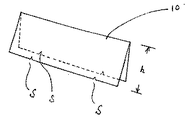
図4は折り曲げた襞部材の概略斜視図である。図4の実施形態では、縫着部に相当する二箇所の部位に小さな切欠部Sを有し、二つ折りにした物である。折り曲げ部がカード上部の出し入れ口側に相当する。カード収納室の二倍の深さがあるものを切欠部を有するように打ち抜くか、カード収納室の二倍の深さがあるものを打ち抜いた後、鋏み等で切欠部を切り取る事等により襞部材とする。図4の実施形態では縫着部二箇所に切欠部を備えているが、更に左右の縁部近傍の縫着部にも前記のような切欠部を備えていても良い。しかし該Sは二箇所で十分である。このような切欠部を備える事により、折り曲げた襞部材を積層し縫着する際、縫着部位を正確に位置決めし、かつ直線状の縫着ラインを形成する事が可能である。即ち多数のカード収納襞を正確に位置決めし、どのカード収納襞も正確な六角形のカード収納室を形成する事が出来る。
又二つ折りした後その下部近傍を接着剤で接着し一個の襞部材とする事も可能である。接着した襞部材はカード収納襞の下部近傍が開口せず、しかもほつれ等が阻止できる。
又二つ折りした襞部材はそのカードの出し入れ口に相当する上部の縁部の解れ等が防止できる。従つて長期間使用可能である。In the embodiment according to the present invention, the heel member can use a fabric having a size corresponding to one card storage room.
FIG. 4 is a schematic perspective view of the bent collar member. In the embodiment of FIG. 4, there are small cutout portions S at two portions corresponding to the sewn portion, which are folded in half. The bent portion corresponds to the slot at the top of the card. Either punching out a card with a depth twice that of the card storage room with a notch, or punching out a card with a depth of twice as much as the card storage chamber, A member. In the embodiment of FIG. 4, the notched portions are provided at two sewing portions, but the above-described notched portions may also be provided in the sewn portions near the left and right edges. However, two locations are sufficient for the S. By providing such a notch, it is possible to accurately position the sewing site and form a linear sewing line when the folded collar members are stacked and sewn. That is, it is possible to accurately position a large number of card storage boxes, and any card storage box can form an accurate hexagonal card storage chamber.
Alternatively, after folding in half, the vicinity of the lower part can be bonded with an adhesive to form a single eaves member. The glued gutter member does not open in the vicinity of the lower part of the card housing gutter and can prevent fraying and the like.
Further, the hook member folded in two can prevent the upper edge corresponding to the card slot from being unwound. Therefore, it can be used for a long time.
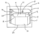
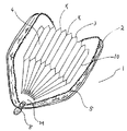
本発明の実施形態において、カードケースに補助収納室を備える事が出来る。図3は補助収納室とカード収納室の概略斜視図である。図3の実施形態では外包材の内部に補助収納室13を備え、更にカード収納襞3を備えている。補助収納室は補助収納室部材14が外包材に糸で縫着されている。又補助収納室部材14はその底部が縫着され閉塞されている。又その上部に留め具8を備えた蓋15が接合されている。この補助収納室は、深さがカード収納室の深さよりも大に構成されている。手前側の襞部材10は補助収納室部材14に左右二箇糸で直線状に縫着されている。二枚の襞部材がその屈曲部Kで縫着され六角形のカード収納室4を構成している。又カード収納室の上部、底部は共に開口し連通した構造となつている。又カード収納襞は、その底部と外包材の底部との間に空隙を有するように配置されている。なお補助収納室部材は前記襞部材や外包材等で例示したような各種の布帛が使用可能である。又補助収納室は留め具がある事が好ましいがなくとも良い。 In the embodiment of the present invention, an auxiliary storage chamber can be provided in the card case. FIG. 3 is a schematic perspective view of the auxiliary storage chamber and the card storage chamber. In the embodiment of FIG. 3, an
本発明に係る他の実施形態において、補助収納室はカードケースの各種の位置に装着が可能である。例えば、カード収納襞郡のほぼ中央部に備えたもの、外包材の表面側に備えたもの、外包材の表面側に一室、外包材内部の側面に一室備えたもの等が例示できる。
又補助収納室は、外包材に多層構造の表面布帛や内面布帛等を配置し、その一部の布帛を補助収納室部材として兼用する事が可能である。又補助収納室部材として透明な布帛を配置する事が可能である。In another embodiment according to the present invention, the auxiliary storage chamber can be mounted at various positions of the card case. For example, one provided in a substantially central portion of the card storage Gamagori, one provided on the surface side of the outer packaging material, one room on the surface side of the outer packaging material, one provided on the side surface inside the outer packaging material, and the like can be exemplified.
In the auxiliary storage chamber, it is possible to arrange a surface fabric, an inner surface fabric or the like having a multilayer structure on the outer packaging material, and to use a part of the fabric as an auxiliary storage chamber member. Moreover, it is possible to arrange a transparent fabric as an auxiliary storage chamber member.
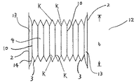
本発明に係る実施形態において、カードケース1はカード収納襞群全体を外包材に包み込んだ構造とすることが出来る。図9の実施形態は留め具8としてチヤツクを備え、カード収納襞郡全体を外包材の内部に包み込んだ構造の物である。この実施形態では10個のカード収納襞を備えている。それぞれの襞部材の屈曲部Kが糸で深さ方向に直線状に縫着され、六角形のカード収納室を備えている。又最初の襞部材と最後の襞部材は内面布帛に糸で縫着され、更に内面布帛が外包材に接合されている。この接合により、チヤツクを開き、更に外包材をカード収納室の幅w方向に開いた時、カード収納室の幅が大となるように構成されている。又カード収納襞群はその底部に空隙Mが5から20mmあるように配置されている。 In the embodiment according to the present invention, the card case 1 may have a structure in which the entire card storage case group is wrapped in an outer packaging material. The embodiment of FIG. 9 has a structure in which a chuck is provided as the
延設部を有する外包材の内側にカード収納襞を11個備えたカードケース1を製造した。カード収納襞3は一個の収納襞に一室のカード収納室を備えたものであつた。又外包材の延設部の内面と左側の表面部に留め具8を備えたものであつた。外包材2は厚み0.5mmの板紙を芯材として用いた。この板紙は比較的硬質で且つ柔軟性を兼ね備えたものであつた。この板紙を両手で曲げた時、くつきりした角部が具現せずゆるやかに湾曲し、曲げ追従性があるものであつた。この板紙を切断し長さ85mm、延設部を含む全体の幅が245mmの芯材とした。図7に示すように、この芯材の中央折り曲げ部V及び延設部折り曲げ部Rにそれぞれ二本ずつプレス線23を押圧した。この幅mは15mmであつた。又線M自体の幅は約0.7mmであつた。 A card case 1 having 11 card storage baskets inside an outer packaging material having an extending portion was manufactured. The
クレープ加工されたポリエチレンテレフタレート繊維織物を、芯材の寸法より折り曲げ部の幅分大きい寸法に切断し表面布帛とした。この布は黒色に染色されたものであつた。表面布帛に芯材を重ね、幅15mmの折り曲げ部18を内側に折り曲げ酢酸ビニル系の接着剤を用い芯材に接着し、図7に示すような表面部材5を得た。なお表面布帛は延設部の反対側表面の所定部位に面留め具8を縫着したものを用いた。この留め具は布に略U状の繊維が多数植毛されたものであつた。 The creped polyethylene terephthalate fiber woven fabric was cut into a size larger than the size of the core material by the width of the bent portion to obtain a surface fabric. This fabric was dyed black. The core material was overlapped on the surface fabric, the
内面部材として、厚み0・2mmの板紙を芯材とし、この芯材にポリエチレンテレフタレート不織布を接合した物を使用した。この芯材は前記表面部材の芯材よりも幅や長さが10mm小さいものであつた。又折り曲げ部VやR等に二本ずつのプレス線を押圧した。内面布帛はその折り曲げ部を外側に折り曲げ、酢酸ビニル系の接着剤で接着した。なお内面布帛は延設部の所定の内面に面留め具8を糸で縫着したものを用いた。この留め具は布に略J状の繊維が多数植毛された物であつた。 As the inner surface member, a paperboard having a thickness of 0.2 mm was used as a core material, and a polyethylene terephthalate nonwoven fabric bonded to the core material was used. This core material was 10 mm smaller in width and length than the core material of the surface member. In addition, two press lines were pressed against the bent portions V, R, and the like. The inner fabric was folded at the folded portion and bonded with a vinyl acetate adhesive. In addition, the inner surface fabric used what sewn the
襞部材10としてポリエチレンテレフタレート不織布を用いた。この不織布を縦120mm、横68mmに切断した。更に上部の縁部、及び下部の縁部に二個ずつ図4に示すような切欠部Sを設けた。夫々の切欠部Sは端部から15mmの位置に設けた。この不織布を図4に示すように二つ折りし、更にその下部を酢酸ビニル系の接着剤で接着し、深さhが60mmの襞部材とした。この襞部材を22個製造した。この襞部材は、硬さ指数が接着前の不織布で28であつた。
前記襞部材を重ね屈曲部に相当する切欠部Sや縁部9近傍を糸で直線状に縫着した。このカード収納襞群は、両手で開くと適度のバネ様の抵抗感があり、離すと自然に密着するものであつた。
更に襞部材を前記内面部材に積層し、最初の襞部材と最後の襞部材それぞれの屈曲部を糸で縫着した。なお襞部材はその底部と内面部材の底部との距離が10mmとなるように縫着した。
前記カード収納襞が縫着された内面部材を、前記表面部材に重ね、夫々の折り曲げ部が一致するように位置決めした。更に酢酸ビニル系の接着剤を用い、内面部材の外側を接着し、図1に示すようなカードケース1を得た。A polyethylene terephthalate nonwoven fabric was used as the
The heel member was overlapped, and the notch S corresponding to the bent portion and the vicinity of the edge 9 were sewn linearly with a thread. This group of card holders had moderate spring-like resistance when opened with both hands, and naturally adhered when released.
Further, the collar member was laminated on the inner surface member, and the bent portions of the first collar member and the last collar member were sewn with a thread. The collar member was sewn so that the distance between its bottom and the bottom of the inner surface member was 10 mm.
The inner surface member to which the card storage rod was sewn was overlapped with the surface member and positioned so that the respective bent portions coincided with each other. Furthermore, the outer side of the inner surface member was bonded using a vinyl acetate adhesive to obtain a card case 1 as shown in FIG.
このカードケースは、折り畳み更に留め具で外包材を留めた状態で、幅fが95mm、厚みgが15mm、長さdが85mmであつた。又カード収納室の長さpが62mm、深さhが60mmであつた。
又外包材2は、表面部材5より内面部材が小さく、内面側に現れる表面布帛の幅cが5mmであつた。
このカードケース1は11個のカード収納襞に11室のカード収納室4を備えたものであつた。このカードケースは外包材2を開いた時、それぞれのカード収納室すべてその幅wが大となり、且つ六角形となるものであつた。又その屈曲部に針孔がありしかも屈曲部がシャープであつた。開いたとき、中央部のカード収納室で幅wが約13mmであつた。
又カード収納襞の底部と外包材の底部間に幅10mmの空隙Mがあるものであつた。
このカードケースに11個のカードを一室に一枚ずつカードの底部がカードケースの底部に接するように収納した。なおカードは57mm×86mmで、その 長尺部の端部がカードケースの底部に当接するように挿入した。即ちカード収納室の底部から10mm延出した状態でカードを収納した。
このカードケースは留め具で留めたとき、隣接するカード収納室が密着しカード収納性が良く、しかも嵩張らずコンパクト性に優れたものであつた。又外包材を開いたとき、それぞれのカード収納室はその幅wが大となり、且つ六角形となるものであつた。又隣接するカードが離れ、カードが立体的に立ち上がリ、カードの識別や出し入れ等が容易に出来るものであつた。しかも開いたときカード収納室の長さpが小となり、カード収納室の両端部の屈曲部Kでカードの両縁部が挟みこまれるようになるものであつた。又外包材を開いた時カードの下部近傍の両面がカード収納室の底部近傍に挟みこまれるようになるものであつた。カードケースを開いた状態でカードの垂直状態から135度下方に傾斜したがカードは脱落せず全て収納されていた。なおこの傾斜角度は図1の状態から更に約45度下方に傾斜した事を意味する。又外包材の開閉時に、襞部材の屈曲部がバネ様の弾性があり、急激な開閉とならず、若干抵抗感のある自然な開閉が出来た。
又カードケース内部の底部に空隙Mがあるので、底部の掃除が容易に可能なものであつた。又カードケースはその表面布帛が適度のザラツキ感があり、風合いが良いものであつた。This card case was folded, and the outer packaging material was fastened with a fastener, and the width f was 95 mm, the thickness g was 15 mm, and the length d was 85 mm. The length p of the card storage chamber was 62 mm, and the depth h was 60 mm.
Further, the
This card case 1 was provided with 11
In addition, there was a gap M having a width of 10 mm between the bottom of the card storage case and the bottom of the outer packaging material.
Eleven cards were stored in this card case one by one so that the bottom of the card was in contact with the bottom of the card case. The card was 57 mm × 86 mm, and was inserted so that the end of the long part was in contact with the bottom of the card case. That is, the card was stored in a state extending 10 mm from the bottom of the card storage chamber.
When this card case was fastened with a fastener, the adjacent card storage chambers were in close contact with each other, the card storage was good, and the card case was not bulky and excellent in compactness. When the outer packaging material was opened, each card storage chamber had a large width w and a hexagonal shape. In addition, the adjacent cards are separated, the cards rise up three-dimensionally, and the cards can be easily identified and put in and out. Moreover, when the card is opened, the length p of the card storage chamber becomes small, and both edges of the card are sandwiched between the bent portions K at both ends of the card storage chamber. Also, when the outer packaging material is opened, both sides near the bottom of the card are sandwiched between the bottom of the card storage chamber. While the card case was opened, the card was tilted 135 degrees downward from the vertical state of the card, but the card was not dropped and was all stored. This inclination angle means that the inclination is further lowered by about 45 degrees from the state of FIG. In addition, when the outer packaging material was opened and closed, the bent portion of the eaves member had spring-like elasticity, so that it could not be suddenly opened and closed, but a natural opening and closing with a slight resistance.
Further, since there is a gap M at the bottom inside the card case, the bottom can be easily cleaned. Further, the card case had a suitable surface texture and a good texture.
動物皮革を用いた外包材の内部にカード収納襞を10個備えたカードケースを製造した。このカードケースは図9に示すように一個のカード収納襞に六角形のカード収納室を一室備えたものであつた。又留め具8としてチヤツクを備えたものであつた。
襞部材10やカード収納襞3等は前記実施例1に同じ物を使用した。但し、カード収納襞は10個備えたものを使用した。又内面布帛として綿平織物が糊剤で処理された布を用いた。この布帛は硬さ指数が24であつた。この内面布帛に前記カード収納襞を糸で左右二箇所ずつ縫着した。なおカード収納襞はその底部と外包材の底部に空隙Mが12mmあるように縫着した。
褐色に着色された牛皮を外包材として用いた。この牛皮を切断し二つ折りし、更にチヤツクを糸で縫着した。
前記カード収納襞が縫着された内面布帛を外包材の内側に入れ、更に糸で縫着し、図9に示すようなカードケース1を製造した。A card case having 10 card storage baskets inside an outer packaging material using animal leather was manufactured. As shown in FIG. 9, this card case has a single card storage box provided with a hexagonal card storage chamber. The
The same thing as Example 1 was used for the
Brown skinned cowhide was used as the outer packaging material. The cowhide was cut and folded in half, and the chuck was sewn with a thread.
The inner surface fabric, to which the card storage bag was sewn, was put inside the outer packaging material, and further sewn with a thread to produce a card case 1 as shown in FIG.
このカードケースは、チヤツクで外包材を留めた状態で、厚みが13mm、幅が95mm、長さが95mmであつた。又カード収納室の長さpが62mm、深さhが60mmであつた。
このカードケース1は10個のカード収納襞に10室のカード収納室4を備えたものであつた。このカードケースはチヤツクを開け外包材を開いた時、それぞれのカード収納室すべてその幅wが大となり、且つ六角形となるものであつた。開いたとき、中央部のカード収納室で幅wが約12mmであつた。
又カード収納襞の底部と外包材の底部に幅12mmの空隙Mがあるものであつた。
このカードケースに10個のカードを一室に一枚ずつ収納した。なおカードは57mm×86mmで、その短尺部の端部がカードケースの底部に当接するように挿入した。This card case had a thickness of 13 mm, a width of 95 mm, and a length of 95 mm with the outer packaging material fastened with a chuck. The length p of the card storage chamber was 62 mm, and the depth h was 60 mm.
This card case 1 was provided with 10
Further, there was a gap M having a width of 12 mm between the bottom of the card storage case and the bottom of the outer packaging material.
Ten cards were stored in the card case one by one. The card was 57 mm × 86 mm, and was inserted so that the end of the short part was in contact with the bottom of the card case.
このカードケースはチヤツクで留めたとき、隣接するカード収納室が密着しカード収納性が良く、しかも嵩張らずコンパクト性に優れたものであつた。チヤツクを開け、外包材を開いたとき、それぞれのカード収納室はその幅wが大となり、且つ六角形となるものであつた。又その屈曲部に針孔がありしかも屈曲部がシャープであつた。又隣接するカードが離れ、カードが立体的に立ち上がリ、カードの識別や出し入れ等が容易に出来るものであつた。しかも開いたときカード収納室の長さpが小となり、カード収納室の両端部の屈曲部Kでカードの両縁部が挟みこまれるようになるものであつた。又外包材を開いた時カードの下部近傍の両面がカード収納室の底部近傍に挟みこまれるようになるものであつた。カードケースを開いた状態でカードの垂直状態から135度下方に傾斜したがカードは脱落せず全て収納されていた。又外包材の開閉時に、襞部材の屈曲部がバネ様の弾性があり、急激な開閉とならず、若干抵抗感のある自然な開閉が出来た。
又カードケース内部の底部に空隙Mがあるので、底部の掃除が容易に可能なものであつた。又カードケースはその表面側が適度の柔らかさがあり、風合いが良いものであつた。When this card case is fastened with a chuck, the adjacent card storage chambers are in close contact with each other, the card storage property is good, and the card case is not bulky and has excellent compactness. When the chuck was opened and the outer packaging material was opened, each card storage chamber had a large width w and a hexagonal shape. The bent part had a needle hole and the bent part was sharp. In addition, the adjacent cards are separated, the cards rise up three-dimensionally, and the cards can be easily identified and put in and out. Moreover, when the card is opened, the length p of the card storage chamber becomes small, and both edges of the card are sandwiched between the bent portions K at both ends of the card storage chamber. Also, when the outer packaging material is opened, both sides near the bottom of the card are sandwiched between the bottom of the card storage chamber. While the card case was opened, the card was tilted 135 degrees downward from the vertical state of the card, but the card was not dropped and was all stored. In addition, when the outer packaging material was opened and closed, the bent portion of the eaves member had spring-like elasticity, so that it could not be suddenly opened and closed, but a natural opening and closing with a slight resistance.
Further, since there is a gap M at the bottom inside the card case, the bottom can be easily cleaned. The card case had moderate softness on the surface side and a good texture.
1 カードケース
2 外包材
3 カード収納襞
4 カード収納室
5 表面部材
6 内面部材
7 狭小な間隙
8 留め具
9 カード収納襞の縁部
10 襞部材
11 長さが大のカード収納室
12 カード収納襞群
13 補助収納室
14 補助収納室部材
15 蓋
16 表面布帛
17 内面布帛
18 布帛の折り曲げ部
19 芯材
20 縫着ライン
21 上部の開口部
22 下部の開口部
23 プレス線
24 延設部DESCRIPTION OF SYMBOLS 1
K 屈曲部
M 空隙
R 延設部の折り曲げ部
S 切欠部
V 中央折り曲げ部K bent part M gap R extended part bent part S notch part V central bent part
b 補助収納室の長さ
c 表面布帛が内面に現れる幅
d カードケースの長さ
f カードケースの幅
g カードケースの厚み
h カード収納室の深さ
m 芯材の折り曲げ幅
p カード収納室の長さ
w カード収納室の幅b Length of auxiliary storage chamber c Width at which surface fabric appears on the inner surface d Card case length f Card case width g Card case thickness h Card storage chamber depth m Core material folding width p Card storage chamber length Width of card storage room
Claims (10)
Priority Applications (1)
| Application Number | Priority Date | Filing Date | Title |
|---|---|---|---|
| JP2004148416A JP4575025B2 (en) | 2004-04-15 | 2004-04-15 | card case |
Applications Claiming Priority (1)
| Application Number | Priority Date | Filing Date | Title |
|---|---|---|---|
| JP2004148416A JP4575025B2 (en) | 2004-04-15 | 2004-04-15 | card case |
Publications (3)
| Publication Number | Publication Date |
|---|---|
| JP2005296591A true JP2005296591A (en) | 2005-10-27 |
| JP2005296591A5 JP2005296591A5 (en) | 2007-06-07 |
| JP4575025B2 JP4575025B2 (en) | 2010-11-04 |
Family
ID=35328830
Family Applications (1)
| Application Number | Title | Priority Date | Filing Date |
|---|---|---|---|
| JP2004148416A Expired - Fee Related JP4575025B2 (en) | 2004-04-15 | 2004-04-15 | card case |
Country Status (1)
| Country | Link |
|---|---|
| JP (1) | JP4575025B2 (en) |
Cited By (3)
| Publication number | Priority date | Publication date | Assignee | Title |
|---|---|---|---|---|
| JP2009045116A (en) * | 2007-08-14 | 2009-03-05 | Shigeo Nakagawa | Three-dimensional sheet for storage |
| JP2011136535A (en) * | 2009-12-28 | 2011-07-14 | Kuramatsu Yashiro | Filing implement |
| WO2017091642A1 (en) * | 2015-11-27 | 2017-06-01 | Strong Joseph | Holder for rfid enabled cards |
Citations (3)
| Publication number | Priority date | Publication date | Assignee | Title |
|---|---|---|---|---|
| JPS6370377U (en) * | 1986-10-27 | 1988-05-11 | ||
| JPH0345713U (en) * | 1990-08-31 | 1991-04-26 | ||
| JPH0390713U (en) * | 1989-10-17 | 1991-09-17 |
-
2004
- 2004-04-15 JP JP2004148416A patent/JP4575025B2/en not_active Expired - Fee Related
Patent Citations (3)
| Publication number | Priority date | Publication date | Assignee | Title |
|---|---|---|---|---|
| JPS6370377U (en) * | 1986-10-27 | 1988-05-11 | ||
| JPH0390713U (en) * | 1989-10-17 | 1991-09-17 | ||
| JPH0345713U (en) * | 1990-08-31 | 1991-04-26 |
Cited By (5)
| Publication number | Priority date | Publication date | Assignee | Title |
|---|---|---|---|---|
| JP2009045116A (en) * | 2007-08-14 | 2009-03-05 | Shigeo Nakagawa | Three-dimensional sheet for storage |
| JP2011136535A (en) * | 2009-12-28 | 2011-07-14 | Kuramatsu Yashiro | Filing implement |
| WO2017091642A1 (en) * | 2015-11-27 | 2017-06-01 | Strong Joseph | Holder for rfid enabled cards |
| US9990574B2 (en) | 2015-11-27 | 2018-06-05 | Joseph James Strong | Holder for RFID enabled cards |
| GB2559941A (en) * | 2015-11-27 | 2018-08-22 | Strong Joseph | Holder for RFID enabled cards |
Also Published As
| Publication number | Publication date |
|---|---|
| JP4575025B2 (en) | 2010-11-04 |
Similar Documents
| Publication | Publication Date | Title |
|---|---|---|
| TWI325309B (en) | ||
| JP6109381B2 (en) | Product group packaging method and package | |
| KR101278069B1 (en) | Cleaning article, fiber raising method for the article, and production method for the article | |
| TW398967B (en) | Disposable wiping article, multiple layer disposable wiping article, and method of making a wiping article | |
| JP4575025B2 (en) | card case | |
| JP5066408B2 (en) | Seat container | |
| JP2008119171A (en) | Cleaning article and method for manufacturing the same | |
| CA2191171A1 (en) | Mouse pad | |
| JP2005199675A (en) | Card storage body | |
| JP2005111244A (en) | Card storage body | |
| US3270791A (en) | Fabric storage device | |
| RU81419U1 (en) | DISPOSABLE FLOOR EXTRA ROOM MAT | |
| US20180042440A1 (en) | Cleaning sheet and cleaning instrument | |
| JP2004203483A (en) | Tissue box | |
| JP2017024782A (en) | Attachment for wiper dispenser and wiper dispenser | |
| JP2021079969A (en) | Sheet package | |
| KR200498625Y1 (en) | Colored paper storage box set | |
| JPH07308216A (en) | Storage case | |
| US9290342B1 (en) | System for singly dispensing fibrous filters from bulk | |
| JP6925494B1 (en) | Sponge spicule capture device | |
| JP3099848U (en) | Pension document storage | |
| JP3232411U (en) | Packaging container and sheet dispenser | |
| JP2021008286A (en) | Sheet package and manufacturing method of sheet package | |
| JP3152454U (en) | Card holder | |
| JP3071972U (en) | Pillow case |
Legal Events
| Date | Code | Title | Description |
|---|---|---|---|
| A521 | Written amendment |
Free format text: JAPANESE INTERMEDIATE CODE: A523 Effective date: 20070411 |
|
| A621 | Written request for application examination |
Free format text: JAPANESE INTERMEDIATE CODE: A621 Effective date: 20070411 |
|
| RD02 | Notification of acceptance of power of attorney |
Free format text: JAPANESE INTERMEDIATE CODE: A7422 Effective date: 20070411 |
|
| A977 | Report on retrieval |
Free format text: JAPANESE INTERMEDIATE CODE: A971007 Effective date: 20091117 |
|
| A131 | Notification of reasons for refusal |
Free format text: JAPANESE INTERMEDIATE CODE: A131 Effective date: 20091124 |
|
| A521 | Written amendment |
Free format text: JAPANESE INTERMEDIATE CODE: A523 Effective date: 20100112 |
|
| TRDD | Decision of grant or rejection written | ||
| A01 | Written decision to grant a patent or to grant a registration (utility model) |
Free format text: JAPANESE INTERMEDIATE CODE: A01 Effective date: 20100810 |
|
| A01 | Written decision to grant a patent or to grant a registration (utility model) |
Free format text: JAPANESE INTERMEDIATE CODE: A01 |
|
| A61 | First payment of annual fees (during grant procedure) |
Free format text: JAPANESE INTERMEDIATE CODE: A61 Effective date: 20100819 |
|
| R150 | Certificate of patent or registration of utility model |
Ref document number: 4575025 Country of ref document: JP Free format text: JAPANESE INTERMEDIATE CODE: R150 Free format text: JAPANESE INTERMEDIATE CODE: R150 |
|
| FPAY | Renewal fee payment (event date is renewal date of database) |
Free format text: PAYMENT UNTIL: 20130827 Year of fee payment: 3 |
|
| R250 | Receipt of annual fees |
Free format text: JAPANESE INTERMEDIATE CODE: R250 |
|
| R250 | Receipt of annual fees |
Free format text: JAPANESE INTERMEDIATE CODE: R250 |
|
| R250 | Receipt of annual fees |
Free format text: JAPANESE INTERMEDIATE CODE: R250 |
|
| R250 | Receipt of annual fees |
Free format text: JAPANESE INTERMEDIATE CODE: R250 |
|
| R250 | Receipt of annual fees |
Free format text: JAPANESE INTERMEDIATE CODE: R250 |
|
| R250 | Receipt of annual fees |
Free format text: JAPANESE INTERMEDIATE CODE: R250 |
|
| R250 | Receipt of annual fees |
Free format text: JAPANESE INTERMEDIATE CODE: R250 |
|
| LAPS | Cancellation because of no payment of annual fees |