JP2005296560A - Piggy bank for automatically changing date - Google Patents
Piggy bank for automatically changing date Download PDFInfo
- Publication number
- JP2005296560A JP2005296560A JP2004142900A JP2004142900A JP2005296560A JP 2005296560 A JP2005296560 A JP 2005296560A JP 2004142900 A JP2004142900 A JP 2004142900A JP 2004142900 A JP2004142900 A JP 2004142900A JP 2005296560 A JP2005296560 A JP 2005296560A
- Authority
- JP
- Japan
- Prior art keywords
- date
- piggy bank
- box body
- drum
- coin
- Prior art date
- Legal status (The legal status is an assumption and is not a legal conclusion. Google has not performed a legal analysis and makes no representation as to the accuracy of the status listed.)
- Pending
Links
- 241001071864 Lethrinus laticaudis Species 0.000 title claims abstract description 6
- 238000005192 partition Methods 0.000 claims description 19
- 230000037431 insertion Effects 0.000 description 5
- 238000003780 insertion Methods 0.000 description 5
- 238000010586 diagram Methods 0.000 description 2
Images

Landscapes
- Purses, Travelling Bags, Baskets, Or Suitcases (AREA)
Abstract
Description
本発明は、お金を投入する事によりのみ日付の変更が可能な貯金箱である。 The present invention is a piggy bank whose date can be changed only by inserting money.
従来は、お金を投入する貯金箱と、日付及びカレンダーと連結のない状態で、カレンダーの付いた貯金箱、及びお金を投入しても自分自身の手で日付を変更していた。 In the past, the date was changed by one's own hand even when the money box was inserted and the money box with the calendar and the money box with the calendar were inserted without being connected to the date and the calendar.
そのために次のような問題点があった。
お金を入れなくても日付が変更できたり、日付を動かすのが面倒になったりするので、日付の変更、及びカレンダーとの連結性の無い状態で使用されるようになっていた。
本発明は以上の問題点を解決しようとするものである。Therefore, there were the following problems.
The date can be changed without making money, and it becomes troublesome to move the date. Therefore, the date has been changed and the connection with the calendar is not used.
The present invention is intended to solve the above problems.
箱本体を設け、箱本体上部に投入口、前面に拡大レンズ付の日付窓を設け、箱内部に貯金空間と機構収納部を隔てる隔壁、機構収納部に軸着された日付ドラム、歯車を連結させ、投入口から投入されたコインにより動作し、日付ドラムを一単位分動かす回転制御機構と投入されたコインを貯金空間に導くガイド機構とより成る日付変更貯金箱。 A box body is provided, a slot is provided at the top of the box body, a date window with a magnifying lens is provided on the front, a partition that separates the storage space from the mechanism storage section, a date drum that is pivotally attached to the mechanism storage section, and gears are connected to the interior of the box. The date-changing piggy bank is composed of a rotation control mechanism that operates by a coin inserted from the insertion slot and moves the date drum by one unit, and a guide mechanism that guides the inserted coin to the saving space.
本発明は、お金を投入する事により自動的に日付が変更する。したがって日付変更、及びカレンダーを変更するという日常生活の動作と関連づけることで興味がわきお金が貯まる。 In the present invention, the date is automatically changed by inserting money. Therefore, it is interesting and saves money by associating it with the daily activities of changing the date and changing the calendar.
以下、本発明の実施の形態を説明する。
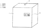
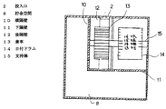
(イ)図1に見るように、箱本体(1)を設け、上部面に投入口(2)、前面に日付窓(3)を設ける。
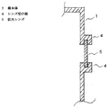
(ロ)図2は図1にある日付窓(3)の詳細であり、箱本体(1)の前面にレンズ受け部(4)を設け、その部分に拡大レンズ(5)を設け、中の文字を大きく見せるようにする。
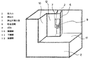
(ハ)図3に見るように、箱本体(1)前面の一部、及び上面の一部を取り外した状態の詳細図であり、投入口(2)の下に突出片を有する押込片(6)、及び押込片の下にばね(9)を設け、押込片(6)が上下に作動できるように、押込片開口部(7)を設け、貯金空間(8)と機構収納部を隔てる横隔壁(10)、下隔壁(11)、後隔壁(12)を設ける。
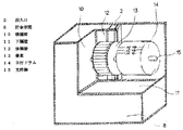
(ニ)図4は図3に機構収納部品を設けた部分を示し、箱本体(1)と横隔壁(10)の間に支持棒(15)を設け、歯車(13)、及び日付ドラム(14)を日付窓(3)に平行かつ同じ高さ、及び横同位置になるように設け、同一軸で軸着させる。またこの日付ドラム(14)は表面に日付が表示されたものであり、30分割あるいは31分割にして、1〜30、あるいは1〜31というように日付が同じ幅となるように表示されている。また歯車(13)はその表示の分割にあわせた数の歯からなっている。
(ホ)図5に見るように、箱本体(1)の前面を取り外した状態の詳細図であり、貯金空間(8)と機構収納部を隔てる横隔壁(10)、下隔壁(11)及び、後隔壁(12)を設け、箱本体(1)と横隔壁(10)の間に支持棒(15)を設け、歯車(13)と日付ドラム(14)を同一軸の支持棒(15)に平行かつ同じ高さ及び、横同位置に軸着させた状態となっている。
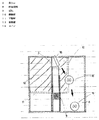
(ヘ)図6は機構収納部の動作を示し、(a)に示すように、投入口(2)にコイン(16)を投入することにより、(b)のように、ばね(9)が縮み、押込片開口部(7)内を押込片(6)が下がり、押込片(6)が歯車(13)の歯に噛み合い、歯車(13)が同軸着した日付ドラム(14)の1回転分のみが廻るようになっている。また投入されたコイン(16)は機構収納部内に絶対に入ることのないように、横隔壁(10)、下隔壁(11)、後隔壁(12)にはばまれ、必ず貯金空間(8)に貯まるようになっている。
本発明は、以上の構成からなりたっていろ。
本発明を使用するときには、箱本体(1)の上面の部分に設けた投入口(2)にコイン(16)を投入すると図6(b)に示すように同時にばね(9)が縮む。また同時に押込片(6)が押込片開口部(7)内を下げる。その時、コイン(16)が貯金空間(8)に必ず落ちるように貯金空間(8)に導くガイド機構〔横隔壁(10)下隔壁(11)後隔壁(12)〕を機構収納部及び貯金空間(8)との間に取り付けられている。押込片(6)が下がることにより箱本体(1)と横隔壁(10)の間に取り付けられた支持棒(15)に軸着された歯車(13)に噛み合い、同一軸着された日付ドラム(14)の1回転分の動作分のみ歯車(13)が廻る。それに連動して日付ドラム(14)が1日分のみ廻り、日付が1日分のみ変更される。その変更された日付ドラム(14)の日付部分を、日付窓(3)に取り付けた拡大レンズ(5)を通して、日付の文字を大きく見ることができる。図6(c)に示すように、コイン(16)が投入され、下げられた投入口(2)がばね(9)の動力により、元の位置に戻るようになっている。Embodiments of the present invention will be described below.
(A) As shown in FIG. 1, a box body (1) is provided, a slot (2) is provided on the upper surface, and a date window (3) is provided on the front surface.
(B) FIG. 2 shows the details of the date window (3) in FIG. 1. A lens receiving part (4) is provided on the front surface of the box body (1), and a magnifying lens (5) is provided on that part. Make the characters look bigger.
(C) As shown in FIG. 3, it is a detailed view of a state in which a part of the front surface of the box body (1) and a part of the upper surface are removed, and a pushing piece having a protruding piece under the insertion port (2) ( 6), and a spring (9) is provided under the pushing piece, and a pushing piece opening (7) is provided so that the pushing piece (6) can be moved up and down to separate the saving space (8) from the mechanism housing portion. A horizontal partition (10), a lower partition (11), and a rear partition (12) are provided.
(D) FIG. 4 shows a portion where the mechanism housing parts are provided in FIG. 3, and a support rod (15) is provided between the box body (1) and the transverse partition wall (10), and the gear (13) and date drum ( 14) is provided parallel to the date window (3), at the same height, and at the same horizontal position, and is attached to the same axis. This date drum (14) has the date displayed on the surface, and is displayed in 30 or 31 divisions so that the dates have the same width, such as 1 to 30, or 1 to 31. . The gear (13) has a number of teeth corresponding to the division of the display.
(E) As shown in FIG. 5, it is a detailed view of the state where the front surface of the box body (1) is removed, and the horizontal bulkhead (10), the lower bulkhead (11) and the partition wall (8) separating the mechanism storage section The rear partition (12) is provided, the support bar (15) is provided between the box body (1) and the horizontal partition (10), and the gear (13) and the date drum (14) are supported on the same axis. In parallel with the same height and at the same horizontal position.
(F) FIG. 6 shows the operation of the mechanism housing portion. As shown in (a), when the coin (16) is inserted into the insertion slot (2), the spring (9) is moved as shown in (b). Shrinking, the pushing piece (6) descends in the pushing piece opening (7), the pushing piece (6) meshes with the teeth of the gear (13), and the rotation of the date drum (14) with the gear (13) attached coaxially Only minutes can be turned. In addition, the inserted coin (16) is caught in the horizontal partition (10), the lower partition (11), and the rear partition (12) so that it never enters the mechanism storage unit, and the saving space (8) is surely formed. It is supposed to accumulate in.
The present invention has the above configuration.
When using the present invention, when the coin (16) is inserted into the insertion slot (2) provided in the upper surface portion of the box body (1), the spring (9) is simultaneously contracted as shown in FIG. 6 (b). At the same time, the pushing piece (6) lowers the inside of the pushing piece opening (7). At that time, the guide mechanism [lateral partition wall (10) lower partition wall (11) rear partition wall (12)] for guiding the coin (16) to the saving space (8) so that the coin (16) always falls into the saving space (8) is moved to the mechanism storage portion and the saving space. It is attached between (8). When the pushing piece (6) is lowered, the date drum is engaged with the gear (13) pivotally attached to the support rod (15) attached between the box main body (1) and the horizontal partition wall (10) and is attached to the same axis. The gear (13) rotates only for the operation of one rotation of (14). In conjunction with this, the date drum (14) rotates only for one day, and the date is changed only for one day. Through the magnifying lens (5) attached to the date window (3), the date character of the date portion of the changed date drum (14) can be seen largely. As shown in FIG. 6C, the coin (16) is inserted, and the lowered insertion port (2) is returned to the original position by the power of the spring (9).
1 箱本体
2 投入口
3 日付窓
4 レンズ受け部
5 拡大レンズ
6 押込片
7 押込片開口部
8 貯金空間
9 ばね
10 横隔壁
11 下隔壁
12 後隔壁
13 歯車
14 日付ドラム
15 支持棒
16 コインDESCRIPTION OF
Claims (1)
Priority Applications (1)
| Application Number | Priority Date | Filing Date | Title |
|---|---|---|---|
| JP2004142900A JP2005296560A (en) | 2004-04-12 | 2004-04-12 | Piggy bank for automatically changing date |
Applications Claiming Priority (1)
| Application Number | Priority Date | Filing Date | Title |
|---|---|---|---|
| JP2004142900A JP2005296560A (en) | 2004-04-12 | 2004-04-12 | Piggy bank for automatically changing date |
Publications (1)
| Publication Number | Publication Date |
|---|---|
| JP2005296560A true JP2005296560A (en) | 2005-10-27 |
Family
ID=35328799
Family Applications (1)
| Application Number | Title | Priority Date | Filing Date |
|---|---|---|---|
| JP2004142900A Pending JP2005296560A (en) | 2004-04-12 | 2004-04-12 | Piggy bank for automatically changing date |
Country Status (1)
| Country | Link |
|---|---|
| JP (1) | JP2005296560A (en) |
Cited By (1)
| Publication number | Priority date | Publication date | Assignee | Title |
|---|---|---|---|---|
| US8075362B2 (en) | 2007-10-03 | 2011-12-13 | Mattel, Inc. | Electronic banking toy |
-
2004
- 2004-04-12 JP JP2004142900A patent/JP2005296560A/en active Pending
Cited By (1)
| Publication number | Priority date | Publication date | Assignee | Title |
|---|---|---|---|---|
| US8075362B2 (en) | 2007-10-03 | 2011-12-13 | Mattel, Inc. | Electronic banking toy |
Similar Documents
| Publication | Publication Date | Title |
|---|---|---|
| JP5923768B2 (en) | Amusement stand | |
| JP5747361B1 (en) | Amusement stand | |
| JP2016087424A (en) | Game machine | |
| JP2018153537A (en) | Game machine | |
| JP2005296560A (en) | Piggy bank for automatically changing date | |
| JP5273854B2 (en) | Defender control device for medal pusher game machine | |
| JP2007061155A (en) | Game machine | |
| JP5555876B2 (en) | Game machine | |
| JP2016202226A (en) | Game machine | |
| JP5526926B2 (en) | Game machine | |
| JP6187916B2 (en) | Amusement stand | |
| JP7030219B2 (en) | Pachinko machine | |
| JP2004129831A (en) | Slot machine | |
| JP2010029251A (en) | Game machine | |
| CN202662085U (en) | Structure for automatic selling machine of tourism commemorative coins | |
| JP5023438B2 (en) | Game machine | |
| KR100432004B1 (en) | turning type coin box | |
| JP6998663B2 (en) | Pachinko machine | |
| JP6047745B2 (en) | Amusement stand | |
| JP4537991B2 (en) | Slot machine | |
| JP2022060413A (en) | Game machine | |
| JP2008237525A (en) | Slot machine | |
| JP5900422B2 (en) | Game machine | |
| JP5900420B2 (en) | Game machine | |
| JP2018202204A (en) | Game machine |