JP2005296536A - Ultrasonic probe - Google Patents
Ultrasonic probe Download PDFInfo
- Publication number
- JP2005296536A JP2005296536A JP2004121031A JP2004121031A JP2005296536A JP 2005296536 A JP2005296536 A JP 2005296536A JP 2004121031 A JP2004121031 A JP 2004121031A JP 2004121031 A JP2004121031 A JP 2004121031A JP 2005296536 A JP2005296536 A JP 2005296536A
- Authority
- JP
- Japan
- Prior art keywords
- ultrasonic probe
- shield case
- piezoelectric plate
- withstand voltage
- matching layer
- Prior art date
- Legal status (The legal status is an assumption and is not a legal conclusion. Google has not performed a legal analysis and makes no representation as to the accuracy of the status listed.)
- Granted
Links
Images

Classifications
-
- B—PERFORMING OPERATIONS; TRANSPORTING
- B06—GENERATING OR TRANSMITTING MECHANICAL VIBRATIONS IN GENERAL
- B06B—METHODS OR APPARATUS FOR GENERATING OR TRANSMITTING MECHANICAL VIBRATIONS OF INFRASONIC, SONIC, OR ULTRASONIC FREQUENCY, e.g. FOR PERFORMING MECHANICAL WORK IN GENERAL
- B06B1/00—Methods or apparatus for generating mechanical vibrations of infrasonic, sonic, or ultrasonic frequency
- B06B1/02—Methods or apparatus for generating mechanical vibrations of infrasonic, sonic, or ultrasonic frequency making use of electrical energy
- B06B1/06—Methods or apparatus for generating mechanical vibrations of infrasonic, sonic, or ultrasonic frequency making use of electrical energy operating with piezoelectric effect or with electrostriction
- B06B1/0644—Methods or apparatus for generating mechanical vibrations of infrasonic, sonic, or ultrasonic frequency making use of electrical energy operating with piezoelectric effect or with electrostriction using a single piezoelectric element
- B06B1/0662—Methods or apparatus for generating mechanical vibrations of infrasonic, sonic, or ultrasonic frequency making use of electrical energy operating with piezoelectric effect or with electrostriction using a single piezoelectric element with an electrode on the sensitive surface
- B06B1/067—Methods or apparatus for generating mechanical vibrations of infrasonic, sonic, or ultrasonic frequency making use of electrical energy operating with piezoelectric effect or with electrostriction using a single piezoelectric element with an electrode on the sensitive surface which is used as, or combined with, an impedance matching layer
Landscapes
- Engineering & Computer Science (AREA)
- Mechanical Engineering (AREA)
- Ultra Sonic Daignosis Equipment (AREA)
Abstract
【目的】シールド機能を維持して、印加電圧による音響整合層の破壊を防止して耐電圧性を維持した超音波探触子を提供する。
【構成】圧電板の外周側面をシールドケースで覆い、前記圧電板及び前記シールドケースを含めた超音波の送受波面に音響整合層を設けてなる超音波探触子において、前記シールドケースの少なくとも開口端面を含む先端側に耐電圧材を設けた構成とする。前記圧電板は遮蔽板によって分割され、前記遮蔽板の端面を含めた先端側に耐電圧材を設けた分割型の超音波探触子とする。また、前記耐電圧材はポリイミドテープとする。
【選択図】図1[Objective] To provide an ultrasonic probe that maintains a shield function, prevents breakdown of an acoustic matching layer due to an applied voltage, and maintains voltage resistance.
In an ultrasonic probe in which an outer peripheral side surface of a piezoelectric plate is covered with a shield case and an acoustic matching layer is provided on an ultrasonic wave transmission / reception surface including the piezoelectric plate and the shield case, at least an opening of the shield case is provided. A withstand voltage material is provided on the tip side including the end face. The piezoelectric plate is divided by a shielding plate, and is a split type ultrasonic probe in which a withstand voltage material is provided on the tip side including the end face of the shielding plate. The withstand voltage material is a polyimide tape.
[Selection] Figure 1
Description
本発明は超音波探触子を技術分野とし、特にシールドケースを有する超音波探触子に関する。 The present invention relates to an ultrasonic probe, and particularly to an ultrasonic probe having a shield case.
(発明の背景)超音波探触子は例えば医用とした超音波診断装置の超音波送受波源として広く知られている。このようなものの一つに、圧電板の外周をシールドケースで覆った超音波探触子がある。 BACKGROUND OF THE INVENTION Ultrasonic probes are widely known as ultrasonic transmission / reception sources of, for example, medical ultrasonic diagnostic apparatuses. One such example is an ultrasonic probe in which the outer periphery of a piezoelectric plate is covered with a shield case.
(従来技術の一例)第4図は一従来例を説明する超音波探触子の断面図である。
超音波探触子は例えば圧電板1、内ケース2、シールドケース3、外ケース4及び音響整合層5を備えてなる。圧電板1は両主面に図示しない駆動電極を有し、表面側の駆動電極は裏面側に接続部が延出する。そして、一対のリード線6が裏面側に接続する。
(Example of Prior Art) FIG. 4 is a cross-sectional view of an ultrasonic probe for explaining one conventional example.
The ultrasonic probe includes, for example, a
内ケース2は開口面側に段部を有し、圧電板1の外周を保持する。そして、圧電板1の裏面側には制動機能を有するバッキング材7が例えば樹脂の流し込みによって設けられる。シールドケース3は内ケース2の外周に設けられ、開口端面を送受波面に接近させて圧電板1の外周を覆う。これにより、外来雑音の侵入を防止して誤診を防止する。
The
外ケース4は、シールドケース3の外周に設けられる。音響整合層5は圧電板1の前面(送受波面)、内ケース2、シールドケース3及び外ケース4の開口端面に設けられ、送受波面の全面を覆う。圧電板1の前面に設けられる音響整合層5の厚みは一般に超音波波長のλ/4に設定される。また、送受波面が当接する生体の安全を確保するため、送受波面の全面に設けられる。
(従来技術の問題点)しかしながら、上記構成の超音波探触子では、シールドケース3に起因して耐電圧性を維持できない問題があった。すなわち、上記構成の超音波探触子では、シールドケース3の開口端面は幅も小さく高電圧の印加によって開口端面近傍(先端側)に電界が集中する。これにより、点線枠Pで示す特に開口端面近傍の音響整合層5が破壊する問題があった。
(Problems of the prior art) However, the ultrasonic probe having the above configuration has a problem that the withstand voltage cannot be maintained due to the
なお、この種の超音波探触子では、通常、4KVの電圧を印加しても破壊を生ずることなく正常に動作する耐電圧性を求められる。例えば圧電素子の両主面の駆動電極及びシールドケース3を外部結線でアース電位として、音響整合層5の前面との間に4KVの電圧を印加して検査する。
It should be noted that this type of ultrasonic probe is normally required to have a voltage resistance that operates normally without being broken even when a voltage of 4 KV is applied. For example, the drive electrodes on both main surfaces of the piezoelectric element and the
(発明の目的)本発明はシールド機能を維持して耐電圧性を維持した超音波探触子を提供することを目的とする。 (Object of the Invention) An object of the present invention is to provide an ultrasonic probe which maintains the shield function and maintains the voltage resistance.
本発明は、特許請求の範囲(請求項1)に示したように、圧電板の外周側面をシールドケースで覆い、前記圧電板及び前記シールドケースを含めた超音波の送受波面に音響整合層を設けてなる超音波探触子において、前記シールドケースの少なくとも開口端面を含む先端側に耐電圧材を設けた構成とする。 According to the present invention, as shown in the claims (Claim 1), the outer peripheral side surface of the piezoelectric plate is covered with a shield case, and an acoustic matching layer is provided on the ultrasonic wave transmission / reception surface including the piezoelectric plate and the shield case. In the ultrasonic probe provided, a withstand voltage material is provided on the tip side including at least the opening end face of the shield case.
上記構成によって、印加電圧が耐電圧材に分圧されてシールドケースの先端側での音響整合層の破壊を防止する。 With the above-described configuration, the applied voltage is divided by the withstand voltage material to prevent the acoustic matching layer from being broken at the tip side of the shield case.
本発明の請求項2に示したように、請求項1の前記圧電板は遮蔽板によって分割され、前記遮蔽板の端面を含めた先端側に耐電圧材を設ける。これにより、分割型とした特にドップラー型とする際、遮蔽板の先端側での音響整合層の破壊を防止する。
As shown in
同請求項3に示したように、請求項1の前記耐電圧材はポリイミドテープとする。これにより、容易に耐電圧性を高められる。
As shown in
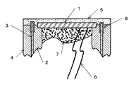
第1図は本発明の第1実施例を説明する超音波探触子の断面図である。なお、前従来例と同一部分には同番号を付与してその説明は簡略又は省略する。 FIG. 1 is a sectional view of an ultrasonic probe for explaining a first embodiment of the present invention. In addition, the same number is attached | subjected to the same part as a prior art example, and the description is simplified or abbreviate | omitted.
超音波探触子は前述同様に裏面側にバッキング材7を充填された圧電板1を内ケース2の段部に保持する。そして、シールドケース3で圧電板1の外周を覆って外ケース4を設け、送受波面の全面に音響整合層5を設けてなる。
As described above, the ultrasonic probe holds the
そして、この実施例では、シールドケース3の開口端面を含む先端側に耐電圧材8を設けてなる。耐電圧材8は例えばポリイミドとした市販の樹脂テープとし、これを先端側の全周に貼着する。樹脂テープの耐電圧強度は概ね400KV/mmであり、この例では25μmの厚みとして10KVの耐電圧強度とする。
In this embodiment, the
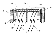
このような構成であれば、超音波探触子の送受波面とアースとの間に印加された電圧V0は、第2図に模式的に示したように音響整合層5と耐電圧材(ポリイミドテープ)8とに分圧されてそれぞれV1、V2になる。そして、音響整合層5には一般に耐電圧強度が20KV/mmのエポキシ樹脂が使用されるため、ポリイミド樹脂とした耐電圧材8の絶縁抵抗が格段に大きい。
In such a configuration, the voltage V0 applied between the transmission / reception surface of the ultrasonic probe and the ground is such that the
したがって、音響整合層5に印加される分圧された電圧V1は小さくなるので、電圧破壊を防止できる。
Accordingly, the divided voltage V1 applied to the acoustic matching
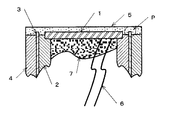
第3図は本発明の第2実施例を説明する超音波探触子の断面図である。なお、前第1実施例と同一部分の説明は省略又は簡略する。 FIG. 3 is a sectional view of an ultrasonic probe for explaining the second embodiment of the present invention. The description of the same parts as in the first embodiment is omitted or simplified.
第2実施例では超音波探触子は圧電板1を分割した送信用と受信用の圧電板1(ab)からなる。そして、送受用の圧電板1(ab)間に遮蔽板9を設けてなる。これは、例えば送信用の圧電板1aから超音波を送出して、受信用の圧電板1bで受波し、特に血流等を測定する所謂ドップラー型として知られるものである。なお、この場合はエアーダンパーとする。
In the second embodiment, the ultrasonic probe includes a piezoelectric plate 1 (ab) for transmission and reception obtained by dividing the
そして、ここでは、前述した耐電圧材8としてのポリイミドテープをシールドケース3のみならず、遮蔽板9の端面を含む先端側に設ける。このような構成であれば、遮蔽板9の先端側における音響整合層5の破壊をも同様な理由によって防止する。
And here, the polyimide tape as the
(他の事項)上記実施例では耐電圧材8はポリイミドテープとしたが、これに限らず、例えば耐電圧性の樹脂を塗布(コーティング)してもよく任意に選択できる。また、シールドケース3は内ケース2と外ケース4の間に介在したが、要は圧電板1の外周をシールドケース3の外周を覆って音響整合層5が設けられた構成の場合に適用できる。また、圧電板1は単板又は分割板としたが、複数の圧電素子を並べた配列型の場合でも同様に適用できる。
(Other matters) Although the
1 圧電板、2 内ケース、3 シールドケース、4 外ケース、5 音響整合層、6 リード線、7 バッキング材、8 耐電圧材、9 遮蔽板。
DESCRIPTION OF
Claims (3)
前記シールドケースの少なくとも開口端面を含む先端側に耐電圧材を設けたことを特徴とする超音波探触子。 In an ultrasonic probe in which an outer peripheral side surface of a piezoelectric plate is covered with a shield case, and an acoustic matching layer is provided on an ultrasonic wave transmission / reception surface including the piezoelectric plate and the shield case,
An ultrasonic probe, characterized in that a withstand voltage material is provided on a tip side including at least an opening end face of the shield case.
Priority Applications (2)
| Application Number | Priority Date | Filing Date | Title |
|---|---|---|---|
| JP2004121031A JP4551111B2 (en) | 2004-04-16 | 2004-04-16 | Ultrasonic probe |
| US11/102,058 US7187108B2 (en) | 2004-04-16 | 2005-04-08 | Ultrasonic probe |
Applications Claiming Priority (1)
| Application Number | Priority Date | Filing Date | Title |
|---|---|---|---|
| JP2004121031A JP4551111B2 (en) | 2004-04-16 | 2004-04-16 | Ultrasonic probe |
Publications (2)
| Publication Number | Publication Date |
|---|---|
| JP2005296536A true JP2005296536A (en) | 2005-10-27 |
| JP4551111B2 JP4551111B2 (en) | 2010-09-22 |
Family
ID=35135715
Family Applications (1)
| Application Number | Title | Priority Date | Filing Date |
|---|---|---|---|
| JP2004121031A Expired - Lifetime JP4551111B2 (en) | 2004-04-16 | 2004-04-16 | Ultrasonic probe |
Country Status (2)
| Country | Link |
|---|---|
| US (1) | US7187108B2 (en) |
| JP (1) | JP4551111B2 (en) |
Cited By (1)
| Publication number | Priority date | Publication date | Assignee | Title |
|---|---|---|---|---|
| US10743757B2 (en) | 2017-09-28 | 2020-08-18 | Nihon Dempa Kogyo Co., Ltd. | Ultrasonic transducer |
Families Citing this family (7)
| Publication number | Priority date | Publication date | Assignee | Title |
|---|---|---|---|---|
| US8456957B2 (en) * | 2008-01-29 | 2013-06-04 | Schneider Electric USA, Inc. | Ultrasonic transducer for a proximity sensor |
| US7804742B2 (en) * | 2008-01-29 | 2010-09-28 | Hyde Park Electronics Llc | Ultrasonic transducer for a proximity sensor |
| KR101145152B1 (en) * | 2009-10-29 | 2012-05-15 | 삼성메디슨 주식회사 | Probe for ultrasonic diagnostic apparatus and manufacturing method thereof |
| JP5411072B2 (en) * | 2010-06-29 | 2014-02-12 | 株式会社日本自動車部品総合研究所 | Ultrasonic sensor |
| US20120274182A1 (en) * | 2011-04-27 | 2012-11-01 | Tung Thih Electronic Co., Ltd. | Ultrasonic sensor |
| EP3295494B1 (en) * | 2015-05-11 | 2022-04-06 | Measurement Specialties, Inc. | Impedance matching layer for ultrasonic transducers with metallic protection structure |
| CN109562414B (en) * | 2016-07-29 | 2021-02-26 | 皇家飞利浦有限公司 | Systems, methods, and apparatus for thermal and drop impact management of ultrasound transducers |
Citations (2)
| Publication number | Priority date | Publication date | Assignee | Title |
|---|---|---|---|---|
| JPH07274297A (en) * | 1994-03-25 | 1995-10-20 | Nippon Dempa Kogyo Co Ltd | Split type ultrasonic probe |
| JPH09294300A (en) * | 1996-04-26 | 1997-11-11 | Olympus Optical Co Ltd | Ultrasonic probe and its manufacture |
Family Cites Families (5)
| Publication number | Priority date | Publication date | Assignee | Title |
|---|---|---|---|---|
| US4387720A (en) * | 1980-12-29 | 1983-06-14 | Hewlett-Packard Company | Transducer acoustic lens |
| JPS59225044A (en) * | 1983-06-07 | 1984-12-18 | 松下電器産業株式会社 | Ultrasonic transducer |
| US5577507A (en) * | 1994-11-21 | 1996-11-26 | General Electric Company | Compound lens for ultrasound transducer probe |
| JP3484358B2 (en) | 1998-10-09 | 2004-01-06 | 日本電波工業株式会社 | Ultrasonic probe |
| JP4118737B2 (en) | 2002-06-03 | 2008-07-16 | 日本電波工業株式会社 | Ultrasonic probe |
-
2004
- 2004-04-16 JP JP2004121031A patent/JP4551111B2/en not_active Expired - Lifetime
-
2005
- 2005-04-08 US US11/102,058 patent/US7187108B2/en not_active Expired - Lifetime
Patent Citations (2)
| Publication number | Priority date | Publication date | Assignee | Title |
|---|---|---|---|---|
| JPH07274297A (en) * | 1994-03-25 | 1995-10-20 | Nippon Dempa Kogyo Co Ltd | Split type ultrasonic probe |
| JPH09294300A (en) * | 1996-04-26 | 1997-11-11 | Olympus Optical Co Ltd | Ultrasonic probe and its manufacture |
Cited By (1)
| Publication number | Priority date | Publication date | Assignee | Title |
|---|---|---|---|---|
| US10743757B2 (en) | 2017-09-28 | 2020-08-18 | Nihon Dempa Kogyo Co., Ltd. | Ultrasonic transducer |
Also Published As
| Publication number | Publication date |
|---|---|
| US7187108B2 (en) | 2007-03-06 |
| US20050236930A1 (en) | 2005-10-27 |
| JP4551111B2 (en) | 2010-09-22 |
Similar Documents
| Publication | Publication Date | Title |
|---|---|---|
| KR101354603B1 (en) | Ultrasound Probe and Manufacturing Method thereof | |
| KR101354604B1 (en) | Ultrasound Probe and Manufacturing Method thereof | |
| CN110448331B (en) | Air-filled ultrasonic transducer | |
| JP4551111B2 (en) | Ultrasonic probe | |
| US7714482B2 (en) | Ultrasonic sensor | |
| US11998397B2 (en) | Thermal conductive layer for transducer face temperature reduction | |
| WO2016104820A1 (en) | Ultrasonic transducer having flexible printed circuit board with thick metal layer and manufacturing method thereof | |
| CN102112060B (en) | Ultrasonic probe | |
| KR20130090038A (en) | Ultrasound probe and manufacturing method thereof | |
| JP2012129662A (en) | Ultrasonic probe | |
| US10429497B2 (en) | Ultrasonic device, ultrasonic probe, electronic apparatus, and ultrasonic imaging apparatus | |
| JP5346182B2 (en) | Intracavity ultrasound probe | |
| JP3212734U (en) | Ultrasonic probe | |
| KR101840523B1 (en) | The intravascular ultrasound transducer manufactured by using polarization inversion of piezoelectric element and method for manufacturing thereof | |
| JP3484358B2 (en) | Ultrasonic probe | |
| JP2006211058A (en) | Ultrasonic probe, ultrasonic diagnostic device and ultrasonic flaw detector | |
| CN211534500U (en) | An air-filled ultrasonic transducer | |
| US20170119346A1 (en) | Ultrasonic device, ultrasonic probe, electronic apparatus, and ultrasonic imaging apparatus | |
| CN218129608U (en) | Energy converter base, energy converter assembly and ultrasonic ablation treatment system | |
| JP4795707B2 (en) | Ultrasonic probe and ultrasonic diagnostic apparatus | |
| JP3305117B2 (en) | Ultrasonic probe | |
| JP6471391B2 (en) | MRI phone | |
| KR101605162B1 (en) | Ultrasonic transducer having thick metal of FPCB and method for manufacture thereof | |
| JP3358964B2 (en) | Array type ultrasonic probe | |
| JPH05199587A (en) | Ultrasonic probe |
Legal Events
| Date | Code | Title | Description |
|---|---|---|---|
| A621 | Written request for application examination |
Free format text: JAPANESE INTERMEDIATE CODE: A621 Effective date: 20070313 |
|
| A977 | Report on retrieval |
Free format text: JAPANESE INTERMEDIATE CODE: A971007 Effective date: 20100209 |
|
| A131 | Notification of reasons for refusal |
Free format text: JAPANESE INTERMEDIATE CODE: A131 Effective date: 20100216 |
|
| A521 | Request for written amendment filed |
Free format text: JAPANESE INTERMEDIATE CODE: A523 Effective date: 20100419 |
|
| TRDD | Decision of grant or rejection written | ||
| A01 | Written decision to grant a patent or to grant a registration (utility model) |
Free format text: JAPANESE INTERMEDIATE CODE: A01 Effective date: 20100706 |
|
| A01 | Written decision to grant a patent or to grant a registration (utility model) |
Free format text: JAPANESE INTERMEDIATE CODE: A01 |
|
| A61 | First payment of annual fees (during grant procedure) |
Free format text: JAPANESE INTERMEDIATE CODE: A61 Effective date: 20100709 |
|
| R150 | Certificate of patent or registration of utility model |
Ref document number: 4551111 Country of ref document: JP Free format text: JAPANESE INTERMEDIATE CODE: R150 Free format text: JAPANESE INTERMEDIATE CODE: R150 |
|
| FPAY | Renewal fee payment (event date is renewal date of database) |
Free format text: PAYMENT UNTIL: 20130716 Year of fee payment: 3 |
|
| FPAY | Renewal fee payment (event date is renewal date of database) |
Free format text: PAYMENT UNTIL: 20130716 Year of fee payment: 3 |
|
| R250 | Receipt of annual fees |
Free format text: JAPANESE INTERMEDIATE CODE: R250 |
|
| R250 | Receipt of annual fees |
Free format text: JAPANESE INTERMEDIATE CODE: R250 |
|
| R250 | Receipt of annual fees |
Free format text: JAPANESE INTERMEDIATE CODE: R250 |
|
| S531 | Written request for registration of change of domicile |
Free format text: JAPANESE INTERMEDIATE CODE: R313531 |
|
| R350 | Written notification of registration of transfer |
Free format text: JAPANESE INTERMEDIATE CODE: R350 |
|
| R250 | Receipt of annual fees |
Free format text: JAPANESE INTERMEDIATE CODE: R250 |
|
| R250 | Receipt of annual fees |
Free format text: JAPANESE INTERMEDIATE CODE: R250 |
|
| R250 | Receipt of annual fees |
Free format text: JAPANESE INTERMEDIATE CODE: R250 |
|
| R250 | Receipt of annual fees |
Free format text: JAPANESE INTERMEDIATE CODE: R250 |
|
| R250 | Receipt of annual fees |
Free format text: JAPANESE INTERMEDIATE CODE: R250 |
|
| R250 | Receipt of annual fees |
Free format text: JAPANESE INTERMEDIATE CODE: R250 |
|
| R250 | Receipt of annual fees |
Free format text: JAPANESE INTERMEDIATE CODE: R250 |
|
| R250 | Receipt of annual fees |
Free format text: JAPANESE INTERMEDIATE CODE: R250 |
|
| EXPY | Cancellation because of completion of term |