JP2005296534A - Electronic endoscope apparatus - Google Patents
Electronic endoscope apparatus Download PDFInfo
- Publication number
- JP2005296534A JP2005296534A JP2004121003A JP2004121003A JP2005296534A JP 2005296534 A JP2005296534 A JP 2005296534A JP 2004121003 A JP2004121003 A JP 2004121003A JP 2004121003 A JP2004121003 A JP 2004121003A JP 2005296534 A JP2005296534 A JP 2005296534A
- Authority
- JP
- Japan
- Prior art keywords
- signal
- pixels
- circuit
- image
- electronic
- Prior art date
- Legal status (The legal status is an assumption and is not a legal conclusion. Google has not performed a legal analysis and makes no representation as to the accuracy of the status listed.)
- Granted
Links
- 238000003384 imaging method Methods 0.000 claims description 10
- 239000003990 capacitor Substances 0.000 claims description 9
- 230000015556 catabolic process Effects 0.000 claims description 3
- 238000010276 construction Methods 0.000 abstract 1
- 238000006243 chemical reaction Methods 0.000 description 16
- 230000000875 corresponding effect Effects 0.000 description 9
- 238000001514 detection method Methods 0.000 description 4
- 238000010586 diagram Methods 0.000 description 4
- 238000001444 catalytic combustion detection Methods 0.000 description 3
- 101000860173 Myxococcus xanthus C-factor Proteins 0.000 description 2
- 230000005540 biological transmission Effects 0.000 description 2
- 235000019800 disodium phosphate Nutrition 0.000 description 2
- 238000005286 illumination Methods 0.000 description 2
- 238000000034 method Methods 0.000 description 2
- 230000007704 transition Effects 0.000 description 2
- 238000004891 communication Methods 0.000 description 1
- 230000001276 controlling effect Effects 0.000 description 1
- 230000002596 correlated effect Effects 0.000 description 1
- 239000013078 crystal Substances 0.000 description 1
- 230000007274 generation of a signal involved in cell-cell signaling Effects 0.000 description 1
- 238000002955 isolation Methods 0.000 description 1
- 230000000750 progressive effect Effects 0.000 description 1
- 230000004044 response Effects 0.000 description 1
- 238000005070 sampling Methods 0.000 description 1
- 230000011664 signaling Effects 0.000 description 1
- 230000001360 synchronised effect Effects 0.000 description 1
- 230000000007 visual effect Effects 0.000 description 1
Images


Landscapes
- Instruments For Viewing The Inside Of Hollow Bodies (AREA)
- Endoscopes (AREA)
- Studio Devices (AREA)
Abstract
Description
本発明は電子内視鏡装置、特に固体撮像素子の画素数の異なる各種の電子内視鏡が使用される環境で、ハイビジョンテレビ方式のモニタへも被観察体映像を出力することができる電子内視鏡装置の構成に関する。 The present invention relates to an electronic endoscope apparatus, particularly an electronic endoscope capable of outputting a subject image to a high-definition television system monitor in an environment where various types of electronic endoscopes having different numbers of pixels of a solid-state imaging device are used. The present invention relates to a configuration of an endoscope apparatus.
電子内視鏡装置は、固体撮像素子であるCCD(Charge Coupled Device)等を電子内視鏡(電子スコープ)の先端部に搭載しており、このCCDは光源装置からの光の照明に基づいて被観察体を撮像する。そして、この電子内視鏡のCCDで得られた撮像信号をプロセッサ装置へ出力し、このプロセッサ装置で映像処理を施すことにより、被観察体の映像をモニタへ表示したり、静止画等を記録装置へ記録したりできるものである。 The electronic endoscope apparatus has a CCD (Charge Coupled Device) or the like, which is a solid-state image sensor, mounted on the tip of an electronic endoscope (electronic scope). The CCD is based on illumination of light from a light source device. The subject is imaged. The imaging signal obtained by the CCD of this electronic endoscope is output to the processor device, and the processor device performs image processing to display the image of the object to be observed on the monitor or record a still image or the like. It can be recorded on the device.
一般に、上記の被観察体映像は、標準テレビジョン方式であるNTSC方式用モニタ(縦横比3:4)に表示されるが、例えば特開平4−253830号公報に示されるように、走査線数が約2倍となる高品位のハイビジョンテレビ(HDTV)方式のモニタ(縦横比9:16)に被観察体映像を表示することも試みられている。電子内視鏡装置では、CCDの出力信号から通常のNTSC方式の信号(アナログ信号)が形成されるので、このNTSC信号をハイビジョンテレビ信号へ変換することが行われる。 In general, the above-mentioned object image is displayed on a monitor for NTSC system (aspect ratio 3: 4) which is a standard television system. For example, as disclosed in Japanese Patent Laid-Open No. 4-253830, the number of scanning lines Attempts have also been made to display a subject image on a high-definition television (HDTV) type monitor (aspect ratio 9:16) that is approximately twice as high. In the electronic endoscope apparatus, a normal NTSC system signal (analog signal) is formed from the output signal of the CCD. Therefore, the NTSC signal is converted into a high-definition television signal.
一方、電子内視鏡装置で得られた被観察体の静止画(デジタル信号)は、パーソナルコンピュータ(パソコン)等のファイリング装置で記録媒体に記録し、後にパソコン用モニタへ表示して観察することが行われており、同時にCCDにおいては高解像度となる高画素数のものが用いられる傾向となっている。
上述のように、近年では固体撮像素子であるCCDが高解像度化、高画素数化されていることから、ハイビジョンテレビ方式による映像表示おいても、従来と比較すると画質が向上した被観察体映像を観察できるという利点があるが、上述のようにNTSC信号をハイビジョンテレビ信号へ変換するのでは、NTSC映像信号の解像度に制限され、高画質化されたCCDの解像度を十分に生かすことができないという問題がある。 As described above, in recent years, CCDs, which are solid-state imaging devices, have higher resolutions and higher pixel counts, so even in high-definition television image display, the image of the object to be observed has improved image quality compared to the past. However, if the NTSC signal is converted to a high-definition television signal as described above, it is limited to the resolution of the NTSC video signal, and the resolution of the high-quality CCD cannot be fully utilized. There's a problem.
また、電子内視鏡には上述のように異なる画素数のCCDが搭載されており、このCCD画素数の相違や高画素数化の変遷に対応してハイビジョンテレビ信号への変換回路をプロセッサ装置内に配置し又は更新(交換)するのでは、コスト的に無駄があり、装置が高価になるという問題がある。
更に、医療現場で使用される機器には、EMC(Electro-Magnetic Compatibility)や電気安全性について厳しい規格が要求されており、ハイビジョンテレビ信号への変換のために、パソコン等の専用の大きな装置において上記の医療用の規格が満たされるようにすることも非現実的である。
The electronic endoscope is equipped with a CCD having a different number of pixels as described above, and a processor device for converting a high-definition television signal conversion circuit in response to the difference in the number of CCD pixels and the transition to a higher number of pixels. If they are arranged or updated (replaced), there is a problem that the cost is wasted and the apparatus becomes expensive.
Furthermore, strict standards for EMC (Electro-Magnetic Compatibility) and electrical safety are required for equipment used in the medical field. For conversion to high-definition television signals, a large dedicated device such as a personal computer is required. It is also impractical to ensure that the above medical standards are met.
本発明は上記問題点に鑑みてなされたものであり、その目的は、パーソナルコンピュータ等へ供給するためにデジタル処理した映像出力を利用し、画素数の異なる固体撮像素子を搭載する電子内視鏡を接続する場合でも、解像度を低下させることなく、ハイビジョンテレビ方式の映像を簡単な構成かつ低コストにて得ることができる電子内視鏡装置を提供することにある。 The present invention has been made in view of the above-described problems, and an object of the present invention is to provide an electronic endoscope using solid-state imaging devices having different numbers of pixels, using video output digitally processed for supply to a personal computer or the like. It is an object of the present invention to provide an electronic endoscope apparatus that can obtain a high-definition television system image with a simple configuration and low cost without reducing resolution.
上記目的を達成するために、請求項1に係る発明は、被観察体を撮像するための固体撮像素子の画素数が異なる各種の電子内視鏡をプロセッサ装置に接続可能に構成し、上記固体撮像素子で得られた信号からアナログ映像信号とデジタル映像信号を形成する電子内視鏡装置において、上記プロセッサ装置に配置され、上記固体撮像素子の画素数に対応させかつ外部コンピュータ用表示規格に合わせたデジタル映像信号を形成すると共に、このデジタル映像信号をパラレル−シリアル変換し、差動信号として出力する差動信号出力部と、この差動信号出力部に対し着脱可能に接続され、この差動信号出力部から入力した差動信号に基づいてデジタル映像信号の画素数を検出し、この画素数に応じて映像信号をハイビジョンテレビ信号へ変換し出力するハイビジョン方式変換器と、を設けたことを特徴とする。
請求項2に係る発明は、上記ハイビジョン方式変換器には、映像を電子的に拡大する電子拡大回路を設け、任意に拡大した映像のハイビジョンテレビ信号を形成することを特徴とする。
請求項3に係る発明は、上記差動信号出力部と上記ハイビジョン方式変換器とを、所定の耐圧を維持するためのパルストランス又はコンデンサを用いて構成した差動形回路で接続することを特徴とする。
In order to achieve the above object, the invention according to
The invention according to
The invention according to claim 3 is characterized in that the differential signal output unit and the HDTV converter are connected by a differential circuit configured using a pulse transformer or a capacitor for maintaining a predetermined breakdown voltage. And
上記の構成によれば、固体撮像素子であるCCDには各種の画素(ピクセル)数を持つものが存在することから、パーソナルコンピュータ等へ出力するための差動信号出力部(例えばDVI)では、640(水平方向)×480(垂直方向)の画素のVGA(Video Graphics Array)、1024×768画素のXGA(eXtended Graphics Array)、1280×960画素、1280×1024画素のSXGA(Super XGA)等の規格に合わせたデジタル映像信号が形成され、この映像信号がパラレル−シリアル変換された後、差動信号としてパソコン用モニタ等へ出力される。この差動信号であるデジタル映像信号がハイビジョン方式変換器へ供給されると、その映像信号の画素数が検出され、この画素数に応じたハイビジョンテレビ信号が形成される。即ち、CCDの全ての画素情報を生かす形で、ハイビジョン信号が得られる。従って、このハイビジョン方式変換器をプロセッサ装置に接続するだけで、ハイビジョン用モニタで被観察体映像(動画又は静止画)を観察することができ、またこの映像はハイビジョン用記録装置に記録することができる。 According to the above configuration, there are CCDs having various numbers of pixels (pixels), which are solid-state image pickup devices. Therefore, in a differential signal output unit (for example, DVI) for outputting to a personal computer or the like, 640 (horizontal direction) × 480 (vertical direction) pixel VGA (Video Graphics Array), 1024 × 768 pixel XGA (eXtended Graphics Array), 1280 × 960 pixel, 1280 × 1024 pixel SXGA (Super XGA), etc. A digital video signal conforming to the standard is formed, and this video signal is subjected to parallel-serial conversion and then output as a differential signal to a personal computer monitor or the like. When the digital video signal as the differential signal is supplied to the high-definition converter, the number of pixels of the video signal is detected, and a high-definition television signal corresponding to the number of pixels is formed. That is, a high-definition signal can be obtained using all the pixel information of the CCD. Therefore, just by connecting this high-definition converter to the processor device, it is possible to observe the object image (moving image or still image) on the high-definition monitor, and this image can be recorded on the high-definition recording device. it can.
上記請求項2の発明によれば、差動信号出力部から入力した映像が電子拡大回路によって任意の倍率で拡大された後にハイビジョンテレビ信号に変換されることになり、被観察体映像(動画及び静止画)が観察し易い大きさでハイビジョン用モニタに表示される。
また、上記差動信号の入出力(伝送)回路として、パルストランスやコンデンサを用いた差動形回路があるが、請求項3の発明では、このパルストランスやコンデンサの耐圧を電子内視鏡で求められる例えば4kV以上に設定することにより、ハイビジョン方式変換器側(電源)を電子内視鏡(差動信号出力部)側から容易に電気的に分離することができる。
According to the second aspect of the present invention, an image input from the differential signal output unit is enlarged by an electronic enlargement circuit at an arbitrary magnification and then converted into a high-definition television signal. A still image is displayed on a high-definition monitor with a size that allows easy observation.
Further, as the differential signal input / output (transmission) circuit, there is a differential circuit using a pulse transformer and a capacitor. In the invention of claim 3, the breakdown voltage of the pulse transformer and the capacitor is measured by an electronic endoscope. By setting the required 4 kV or more, for example, the high-definition converter side (power supply) can be easily electrically separated from the electronic endoscope (differential signal output unit) side.
本発明の電子内視鏡装置のハイビジョン方式変換器によれば、デジタル映像をパーソナルコンピュータ等へ供給するための差動信号出力部出力を利用して、採用されるCCD画素数(解像度)が異なる電子内視鏡を接続する場合でも、CCDが持つ解像度を低下させることなく、ハイビジョンテレビ方式の映像を簡単な構成かつ低コストで形成し、ハイビジョン用モニタや記録装置に出力することが可能となる。また、このビジョン方式変換器を、医療現場で要求されるEMCや電気安全性の規格を満たしたアダプター装置とすることにより、医療現場におけるハイビジョン映像の観察が容易になるという利点がある。更には、電子拡大回路を設けることにより、観察し易い大きさの被観察体映像をハイビジョン用モニタに表示させることが可能となる。 According to the high-definition converter of the electronic endoscope apparatus of the present invention, the number of CCD pixels (resolution) employed is different using the output of the differential signal output unit for supplying digital video to a personal computer or the like. Even when an electronic endoscope is connected, it is possible to form a high-definition television system image with a simple configuration and low cost without reducing the resolution of the CCD and to output it to a high-definition monitor or recording device. . Further, by using this vision system converter as an adapter device that meets EMC and electrical safety standards required in the medical field, there is an advantage that observation of a high-definition image in the medical field becomes easy. Furthermore, by providing an electronic magnifying circuit, it is possible to display an object image having a size that is easy to observe on the high-vision monitor.
図1乃至図3には、実施例に係る電子内視鏡装置の構成が示されており、まず図3に基づいて全体の構成を説明する。図3において、電子内視鏡(電子スコープ)10には、その先端部に固体撮像素子であるCCD11が設けられており、このCCD11としては、40万画素、80万画素、130万画素等、各種のものが搭載される。また、このCCD11から出力された撮像信号をサンプリングする相関二重サンプリング(CDS)回路12及び電子内視鏡10の識別情報や映像処理情報等を格納するメモリ(EEPROM)13等が設けられる。なお、この電子内視鏡10には、図示していない光源装置の光がライトガイドを介して供給されており、先端部から照明光を出力することにより被観察体が上記CCD11で撮像される。そして、上述した画素数(若しくはその画素数に対応したCCDの転送方式)の異なるCCD11を搭載する各種の電子内視鏡10は、プロセッサ装置16に着脱自在に接続可能となっている。
FIGS. 1 to 3 show the configuration of the electronic endoscope apparatus according to the embodiment. First, the overall configuration will be described with reference to FIG. In FIG. 3, an electronic endoscope (electronic scope) 10 is provided with a
このプロセッサ装置16には、A/D変換器17、映像信号に対し各種の信号処理をするための第1DSP(デジタル信号プロセッサ)19、第2DSP20及び第3DSP21、上記DSP19,20の何れかを選択するためのセレクタ(S)18、上記CCD11から第1及び第2DSP19,20までの回路に対し同期信号やタイミング信号を供給するタイミングジェネレータ22、水晶発振器を有するPLL回路23、各種の制御を実行するマイコン24、上記第3DSP21等に同期信号やタイミング信号を供給するための同期信号発生回路(SSG)25が設けられる。
The processor unit 16 selects an A /
また、上記第3DSP21の後段には、デジタル映像信号を形成するための第4DSP27、そしてDVI(Digital Visual Image)回路28が設けられており、このDVI回路28は、パソコン用モニタ等へ出力するための表示規格、例えばVGA、XGA、SXGA等に対応した映像信号を形成し、その後にパラレル−シリアル変換し、このシリアル信号を差動信号としてパソコン用モニタやファイリング装置等へ出力する。このDVIは、DDWG(Digital Display Working Group)が設定した高速スピードのディスプレイ用インターフェースで、データフォーマットにTMDS(Transition Minimized Differential Signaling)を採用するものである。一方、上記第4DSP27には、信号変換回路29を介してUSB出力部30やネット出力部31が設けられており、このUSB出力部30、ネット出力部31からはそれぞれの出力形態に合わせた信号が出力される。更に、上記第3DSP21の後段には、デジタル処理された映像信号をアナログ信号へ変換するアナログ信号プロセッサ33、輝度(Y)信号と色差(C)信号を出力するY/C信号出力部34、R(赤),G(緑),B(青)の信号を出力するRGB出力部35が設けられる。
Further, a
そして、上記のDVI回路28の出力部(端子)に着脱可能に接続する形で、ハイビジョン方式変換器37が設けられ、このハイビジョン方式変換器37の出力がHDTV用モニタやHDTV用レコーダへ接続される。なお、図3の構成においてプロセッサ装置16内の回路として説明したものの一部を、電子内視鏡10側に配置する構成にすることができる。
A high-
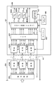
図1には、上記DVI回路28とハイビジョン方式変換器37内の詳細な構成が示されており、DVI回路28では、上述した各表示規格の映像を形成する信号処理部39やRGBの信号、同期信号及び制御信号等を送信するための送信部(エンコーダ/シリアライザ含む)40A,40B,40Cが設けられる。このDVI回路28は、シリアル伝送ケーブル41を介してハイビジョン方式変換器37に接続され、このハイビジョン方式変換器37には、上記3つの送信部40A,40B,40Cに対応した受信部(エンコーダ/シリアライザ含む)42A,42B,42C、ICA(Inter Channel Alignment)部43、映像の画素数を検出してハイビジョンテレビ信号を形成するHDTV(ハイビジョンテレビ)信号変換部(FPGA−Filed Programmable Gate Array 回路)44、各種の制御を実行するマイコン45、入力した映像信号を一時的に記憶するフレームメモリ46が設けられる。また、上記HDTV信号変換部44には、電子拡大回路47が接続されると共に、コネクタ49との間に、輝度(Y)信号、色差信号であるPr,Pb信号に対応してD/A変換器48A,48B,48Cが設けられる。
FIG. 1 shows a detailed configuration of the
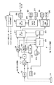
図2には、上記HDTV信号変換部44内の構成が示されており、このHDTV信号変換部44には、水平同期信号(H)、垂直同期信号(V)、映像信号及びクロック信号を入力して映像信号の画素数を検出する画素数検出回路44a、ハイビジョン映像形成のための同期信号発生回路44b、上記フレームメモリ46に対し映像信号の書込み及び読出しを制御するメモリコントローラ44c、このメモリコントローラ44cから出力されたRGB信号をハイビジョン映像であるY,Pr,Pb信号に変換する信号変換器44dが設けられる。
FIG. 2 shows the configuration of the HDTV
実施例は以上の構成からなり、その作用を図4及び図5を参照しながら説明する。まず、この電子内視鏡装置では、図3のCCD11にて被観察体内が撮像され、その撮像信号はCDS回路12にてサンプリングされ、A/D変換器17でデジタル信号へ変換された後に、セレクタ18へ供給される。このセレクタ18では、接続された電子内視鏡10の種類に応じて第1DSP19と第2DSP20の何れかを選択する。例えば、電子内視鏡10とプロセッサ装置16との通信によってマイコン24がメモリ13内の情報を読み取ることにより、CCD11の画素数(若しくはその画素数に対応したCCDの転送方式)に応じ、第1DSP19(インターラインスキャンの場合)又は第2DSP20(プログレッシブスキャンの場合)を選択する。
The embodiment has the above-described configuration, and the operation thereof will be described with reference to FIGS. First, in this electronic endoscope apparatus, the object to be observed is imaged by the
この第1DSP19又は第2DSP20と第3DSP21では、各種の映像処理が施されることになり、この第3DSP21の出力は、第4DSP27とアナログ信号プロセッサ33へ供給される。この第4DSP27では、デジタル出力のための映像信号が形成されており、この映像信号は、信号変換回路29、USB出力部30及びネット出力部31を介して外部へ出力されると共に、DVI回路28を介してパソコン用モニタ等に出力することができる。一方、上記アナログ信号プロセッサ33では、アナログ出力のための映像信号が形成され、Y/C信号出力部34を介してY信号とC信号が出力されると共に、RGB出力部35を介してR,G,Bの各色信号が出力される。
The
一方、上記DVI回路28の出力がハイビジョン方式変換器37へ供給されると、このハイビジョン方式変換器37ではハイビジョンテレビ信号が形成される。即ち、図1に示されるDVI回路28の信号処理部39によって、CCD11の画素数に対応した例えば640×480(VGA)、1024×768(XGA)、1280×960、1280×1024(SXGA)等の表示規格の映像信号が形成される。そして、この信号処理部39から出力されたパラレル信号[B(青),G(緑),R(赤),H(水平同期信号),V(垂直同期信号),C0,C1,C2,C3(制御信号)等]は、送信部40A〜40Cでシリアル信号に変換され、ケーブル41を介してハイビジョン方式変換器37へ出力される。図1のように、送信部40Aから送信されたB信号とH,V等の信号は受信部42Aで、送信部40Bから送信されたG信号とその他の信号は受信部42Bで、送信部40Cから送信号されたR信号とその他の信号は受信部42Cで受信される。これらの受信部42A〜42Cでは、シリアル信号が元のパラレル信号へ変換され、この信号がICA回路43を介してHDTV信号変換部(FPGA)44へ供給される。
On the other hand, when the output of the
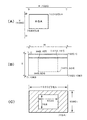
このHDTV信号変換部44では、入力された映像信号が図2のメモリコントローラ44cを介してフレームメモリ46に格納されると同時に、画素数検出回路44aにて入力映像信号の画素数が例えば水平同期信号や垂直同期信号によって検出される。即ち、図4(A)に示されるように、ハイビジョン方式の水平同期信号(H)は1920画素分、垂直同期信号(V)は1080画素分の長さとなるが、例えば変換器37へ入力された映像信号の水平同期信号によって1024の水平画素が検出(カウント)されたとき、又は垂直同期信号によって768の垂直画素が検出されたときは、1024×768のXGA規格の映像(画像)であると判断される。同様に、1280の水平画素又は960の垂直画素が検出されたときは1280×960の映像、640の水平画素又は480の垂直画素が検出されたときは640×480のVGA規格の映像、1208の水平画素又は1024の垂直画素が検出されたときは1280×1024のSXGAの映像であると判断される。そして、この画素数の検出結果が同期信号発生回路44bとメモリコントローラ44cに供給されることにより、メモリコントローラ44cでは画素数に応じてフレームメモリ46からの映像信号の読出し制御が行われる。
In the HDTV
例えば、図4(B)に示されるように、垂直方向の1〜156までは全ての水平画素に黒色を割り当て、垂直方向157番目については、水平方向の449〜1472において上記XGAの映像信号を割り当るというようにして、(449,157)、(1472,157)、(449,924)、(1472,924)の画素で囲まれる範囲の映像信号(RGB信号)が読み出される。その他の画素には、黒色が割り当てられる。そして、信号変換器44dでは、RGB信号がY,Pr,Pb信号へ変換され、このY,Pr,Pb信号と同期信号がHDTV用モニタやHDTV用レコーダへ出力される。このようにして、図4(C)に示されるように、HDTV用モニタには、1024×768画素の被観察体映像を中心領域に配置したハイビジョン映像、即ち1920×1080i(インターレース)の画素の映像(フォーマットD4)が表示される。
For example, as shown in FIG. 4B, black is assigned to all horizontal pixels from 1 to 156 in the vertical direction, and for the 157th vertical direction, the XGA video signal is transmitted from 449 to 1472 in the horizontal direction. In such a manner, video signals (RGB signals) in a range surrounded by the pixels of (449, 157), (1472, 157), (449, 924), and (1472, 924) are read out. Black is assigned to the other pixels. In the
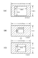
図5(A)には、1280×960画素の映像が検出された場合のハイビジョン映像が示されており、この場合は、HDTV用モニタに1280×960画素の被観察体映像を中心領域に配置したハイビジョン映像が表示される。また、図5(B),(C)には、640×480画素のVGAの映像が検出された場合のハイビジョン映像が示されており、この場合は、図5(B)に示されるように、フォーマットD4によって、640×480画素の被観察体映像を中心に配置したハイビジョン映像を表示してもよいが、やや小さくなるので、実施例では、上記メモリコントローラ44cにてフォーマットD4からフォーマットD3への変換を行い、図5(C)のように、640×480画素の被観察体映像を中心に配置した1280×720iの画素のフォーマットD3のハイビジョン映像を表示させている。
FIG. 5 (A) shows a high-definition video when a video of 1280 × 960 pixels is detected. In this case, an object image of 1280 × 960 pixels is arranged in the central area on the HDTV monitor. The high-definition video is displayed. FIGS. 5B and 5C show high-definition images when a 640 × 480 pixel VGA image is detected. In this case, as shown in FIG. , the format D 4, may display the high-definition image arranged around the
更に、実施例では、図1に示したように電子拡大回路47が設けられており、この電子拡大回路47によって観察し易い大きさ(画像サイズ)に映像を拡大して表示することができる。例えば、このハイビジョン方式変換器37自体に電子拡大率を任意に設定するスイッチ等を設け(或いはプロセッサ装置や外部機器から電子拡大率を設定できるようにしてもよい)、マイコン45を介して電子拡大回路47の拡大率を制御するように構成する。即ち、電子拡大回路47には、HDTV信号変換部44に供給された各種の画素数の映像信号が供給されており、この映像信号から設定倍率に映像拡大された信号が形成され、この拡大映像信号がHDTV信号変換部44へ戻される。そして、HDTV信号変換部44のメモリコントローラ44cでは、この拡大映像信号をフレームメモリ46に書き込んだ後、上述のようにハイビジョン方式に対応させた信号読出しを行うことにより、ハイビジョンテレビ信号が形成される。この結果、ハイビジョン用モニタには、設定倍率で拡大された被観察体映像が表示されることになり、被観察体の観察を更に容易にすることが可能となる。
Furthermore, in the embodiment, an
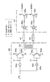
図6及び図7には、上記DVI回路28と上記ハイビジョン方式変換器37とを接続する差動形回路の構成が示されている。図6はパルストランスを用いたものであり、この例では、図示のようにDVI回路28内の差動形ドライバとして、論理回路52a〜52c、トランジスタ53a〜53d、例えば4kV以上の耐圧を維持するパルストランス54等を設け、ハイビジョン方式変換器37内の差動形レシーバとして、コンパレータ55a,55b、トランジスタ56a,56b等を設ける。また、図7はコンデンサを用いたものであり、この例では、図示のようにDVI回路28内に、差動出力回路57等を設け、ハイビジョン方式変換器37内に、例えば4kV以上の耐圧を維持するコンデンサ58a,58bと差動入力回路59等を設ける。
6 and 7 show the configuration of a differential circuit for connecting the
このような差動形回路によれば、上記パルストランス54やコンデンサ58a,58bの耐圧を内視鏡装置で求められる4kV以上に設定するので、別途アイソレーション回路を設けることなく差動信号入出力のため回路を利用して、DVI28とハイビジョン方式変換器37とを商用電源等から電気的に分離することができ、電子内視鏡10の安全性を容易に確保することが可能となる。
According to such a differential circuit, the withstand voltages of the
10…電子内視鏡、 16…プロセッサ装置、
24,45…マイコン、 27…第4DSP、
28…DVI回路(差動信号出力部)、
37…ハイビジョン方式変換器、
44…HDTV(ハイビジョンテレビ)信号変換部、
44a…画素数検出回路、
44c…メモリコントローラ、
46…フレームメモリ、 47…電子拡大回路、
54…パルストランス、
58a,58b…コンデンサ。
10 ... Electronic endoscope, 16 ... Processor device,
24, 45 ... microcomputer, 27 ... 4th DSP,
28 ... DVI circuit (differential signal output unit),
37 ... Hi-Vision converter
44 ... HDTV (high-definition television) signal converter,
44a ... Pixel number detection circuit,
44c ... Memory controller,
46 ... Frame memory, 47 ... Electronic enlargement circuit,
54 ... pulse transformer,
58a, 58b ... capacitors.
Claims (3)
上記プロセッサ装置に配置され、上記固体撮像素子の画素数に対応させかつ外部コンピュータ用表示規格に合わせたデジタル映像信号を形成すると共に、このデジタル映像信号をパラレル−シリアル変換し、差動信号として出力する差動信号出力部と、
この差動信号出力部に対し着脱可能に接続され、この差動信号出力部から入力した差動信号に基づいて上記デジタル映像信号の画素数を検出し、この画素数に応じて映像信号をハイビジョンテレビ信号へ変換し出力するハイビジョン方式変換器と、を設けたことを特徴とする電子内視鏡装置。 Various electronic endoscopes with different numbers of pixels of the solid-state imaging device for imaging the object to be observed are configured to be connectable to the processor device. In the electronic endoscope device to be formed,
A digital video signal arranged in the processor unit, corresponding to the number of pixels of the solid-state imaging device and conforming to a display standard for an external computer is formed, and the digital video signal is parallel-serial converted and output as a differential signal. Differential signal output unit,
The differential signal output unit is detachably connected, and the number of pixels of the digital video signal is detected based on the differential signal input from the differential signal output unit. An electronic endoscope apparatus comprising: a high-definition converter that converts to a TV signal and outputs the signal.
Priority Applications (3)
| Application Number | Priority Date | Filing Date | Title |
|---|---|---|---|
| JP2004121003A JP4493387B2 (en) | 2004-04-16 | 2004-04-16 | Electronic endoscope device |
| US11/105,391 US7773110B2 (en) | 2004-04-16 | 2005-04-14 | Electronic endoscope apparatus |
| CNB2005100673040A CN100370945C (en) | 2004-04-16 | 2005-04-18 | Electronic endoscope apparatus |
Applications Claiming Priority (1)
| Application Number | Priority Date | Filing Date | Title |
|---|---|---|---|
| JP2004121003A JP4493387B2 (en) | 2004-04-16 | 2004-04-16 | Electronic endoscope device |
Publications (2)
| Publication Number | Publication Date |
|---|---|
| JP2005296534A true JP2005296534A (en) | 2005-10-27 |
| JP4493387B2 JP4493387B2 (en) | 2010-06-30 |
Family
ID=35328775
Family Applications (1)
| Application Number | Title | Priority Date | Filing Date |
|---|---|---|---|
| JP2004121003A Expired - Lifetime JP4493387B2 (en) | 2004-04-16 | 2004-04-16 | Electronic endoscope device |
Country Status (1)
| Country | Link |
|---|---|
| JP (1) | JP4493387B2 (en) |
Cited By (3)
| Publication number | Priority date | Publication date | Assignee | Title |
|---|---|---|---|---|
| WO2006013795A1 (en) * | 2004-08-05 | 2006-02-09 | Olympus Corporation | Signal processing device for endoscope |
| EP2123208A2 (en) | 2008-05-20 | 2009-11-25 | FUJIFILM Corporation | Endoscope system with option circuit board |
| JP2015005896A (en) * | 2013-06-21 | 2015-01-08 | オリンパス株式会社 | Endoscope image processing apparatus, endoscope system, and endoscope image processing method |
Citations (13)
| Publication number | Priority date | Publication date | Assignee | Title |
|---|---|---|---|---|
| JPH05176324A (en) * | 1991-12-20 | 1993-07-13 | Fuji Photo Optical Co Ltd | Signal transmission processing circuit for electronic endoscope device |
| JPH07298202A (en) * | 1994-04-21 | 1995-11-10 | Olympus Optical Co Ltd | Image processing unit |
| JPH10286232A (en) * | 1997-04-14 | 1998-10-27 | Asahi Optical Co Ltd | Electronic endoscope device |
| JPH10328145A (en) * | 1997-06-02 | 1998-12-15 | Fuji Photo Optical Co Ltd | Electron endoscope system device |
| JP2000115591A (en) * | 1998-09-30 | 2000-04-21 | Fuji Photo Optical Co Ltd | Video signal transmitter |
| JP2000210251A (en) * | 1999-01-21 | 2000-08-02 | Olympus Optical Co Ltd | Endoscope unit |
| JP2000287203A (en) * | 1999-03-30 | 2000-10-13 | Fuji Photo Optical Co Ltd | Electronic endoscope capable of digital output |
| JP2001157665A (en) * | 1999-09-20 | 2001-06-12 | Asahi Optical Co Ltd | Processor of an electronic endoscope device that outputs a digital video signal |
| JP2001215419A (en) * | 2000-02-02 | 2001-08-10 | Asahi Optical Co Ltd | Electronic endoscope device |
| JP2003024272A (en) * | 2001-07-18 | 2003-01-28 | Olympus Optical Co Ltd | Signal processing device |
| JP2003032529A (en) * | 2001-07-17 | 2003-01-31 | Olympus Optical Co Ltd | Signal processor |
| JP2003333454A (en) * | 2002-05-09 | 2003-11-21 | Victor Co Of Japan Ltd | Image signal processor |
| JP2004000335A (en) * | 2002-05-31 | 2004-01-08 | Olympus Corp | Electronic endoscope apparatus |
-
2004
- 2004-04-16 JP JP2004121003A patent/JP4493387B2/en not_active Expired - Lifetime
Patent Citations (13)
| Publication number | Priority date | Publication date | Assignee | Title |
|---|---|---|---|---|
| JPH05176324A (en) * | 1991-12-20 | 1993-07-13 | Fuji Photo Optical Co Ltd | Signal transmission processing circuit for electronic endoscope device |
| JPH07298202A (en) * | 1994-04-21 | 1995-11-10 | Olympus Optical Co Ltd | Image processing unit |
| JPH10286232A (en) * | 1997-04-14 | 1998-10-27 | Asahi Optical Co Ltd | Electronic endoscope device |
| JPH10328145A (en) * | 1997-06-02 | 1998-12-15 | Fuji Photo Optical Co Ltd | Electron endoscope system device |
| JP2000115591A (en) * | 1998-09-30 | 2000-04-21 | Fuji Photo Optical Co Ltd | Video signal transmitter |
| JP2000210251A (en) * | 1999-01-21 | 2000-08-02 | Olympus Optical Co Ltd | Endoscope unit |
| JP2000287203A (en) * | 1999-03-30 | 2000-10-13 | Fuji Photo Optical Co Ltd | Electronic endoscope capable of digital output |
| JP2001157665A (en) * | 1999-09-20 | 2001-06-12 | Asahi Optical Co Ltd | Processor of an electronic endoscope device that outputs a digital video signal |
| JP2001215419A (en) * | 2000-02-02 | 2001-08-10 | Asahi Optical Co Ltd | Electronic endoscope device |
| JP2003032529A (en) * | 2001-07-17 | 2003-01-31 | Olympus Optical Co Ltd | Signal processor |
| JP2003024272A (en) * | 2001-07-18 | 2003-01-28 | Olympus Optical Co Ltd | Signal processing device |
| JP2003333454A (en) * | 2002-05-09 | 2003-11-21 | Victor Co Of Japan Ltd | Image signal processor |
| JP2004000335A (en) * | 2002-05-31 | 2004-01-08 | Olympus Corp | Electronic endoscope apparatus |
Cited By (5)
| Publication number | Priority date | Publication date | Assignee | Title |
|---|---|---|---|---|
| WO2006013795A1 (en) * | 2004-08-05 | 2006-02-09 | Olympus Corporation | Signal processing device for endoscope |
| US8189041B2 (en) | 2004-08-05 | 2012-05-29 | Olympus Corporation | Endoscope signal processing apparatus |
| EP2123208A2 (en) | 2008-05-20 | 2009-11-25 | FUJIFILM Corporation | Endoscope system with option circuit board |
| JP2015005896A (en) * | 2013-06-21 | 2015-01-08 | オリンパス株式会社 | Endoscope image processing apparatus, endoscope system, and endoscope image processing method |
| US9651767B2 (en) | 2013-06-21 | 2017-05-16 | Olympus Corporation | Image processing apparatus for endoscope, endoscope system and image processing method for endoscope |
Also Published As
| Publication number | Publication date |
|---|---|
| JP4493387B2 (en) | 2010-06-30 |
Similar Documents
| Publication | Publication Date | Title |
|---|---|---|
| CN100370945C (en) | Electronic endoscope apparatus | |
| CN100508873C (en) | Signal processing device for endoscope | |
| US7282025B2 (en) | Electronic endoscope apparatus for connection to adapter unit | |
| CN1697490B (en) | Video apparatus and image pickup apparatus | |
| JPH03174886A (en) | Resolution improvement method and circuit device in television system | |
| JP2005211159A (en) | Electronic endoscope apparatus | |
| JP4435029B2 (en) | Endoscope device | |
| JPH0847000A (en) | Compound-eye image pickup device, image signal conversion device, display device, and compound-eye image pickup image recording / reproducing device | |
| KR101016490B1 (en) | Conversion method and conversion circuit of image data, electronic camera | |
| JP4261673B2 (en) | Electronic endoscope device capable of digital output | |
| JP4493387B2 (en) | Electronic endoscope device | |
| KR100985003B1 (en) | Image processing apparatus of multi-CDC and image processing method | |
| JP4493390B2 (en) | Electronic endoscope device | |
| JP2003333454A (en) | Image signal processor | |
| JP3967060B2 (en) | Electronic endoscope device | |
| KR101012585B1 (en) | Multichannel Image Matching System and Its Method | |
| KR20020037640A (en) | Camera of multi-image processing | |
| JP2005118158A (en) | Electronic endoscope apparatus | |
| JP7586798B2 (en) | Camera and television camera system | |
| JP2003309824A (en) | Image display system | |
| JP3777723B2 (en) | Electronic still camera | |
| JP2005012346A (en) | Video camera apparatus and scan conversion circuit used therefor | |
| JP4637031B2 (en) | Camera monitoring device | |
| JP2000079094A (en) | Electronic endoscopic instrument capable of digital output | |
| JP2000279380A (en) | Electronic endoscope capable of digital output |
Legal Events
| Date | Code | Title | Description |
|---|---|---|---|
| A621 | Written request for application examination |
Free format text: JAPANESE INTERMEDIATE CODE: A621 Effective date: 20061114 |
|
| A711 | Notification of change in applicant |
Free format text: JAPANESE INTERMEDIATE CODE: A711 Effective date: 20090902 |
|
| RD02 | Notification of acceptance of power of attorney |
Free format text: JAPANESE INTERMEDIATE CODE: A7422 Effective date: 20090907 |
|
| A131 | Notification of reasons for refusal |
Free format text: JAPANESE INTERMEDIATE CODE: A131 Effective date: 20091201 |
|
| A521 | Request for written amendment filed |
Free format text: JAPANESE INTERMEDIATE CODE: A523 Effective date: 20100114 |
|
| TRDD | Decision of grant or rejection written | ||
| A01 | Written decision to grant a patent or to grant a registration (utility model) |
Free format text: JAPANESE INTERMEDIATE CODE: A01 Effective date: 20100330 |
|
| A01 | Written decision to grant a patent or to grant a registration (utility model) |
Free format text: JAPANESE INTERMEDIATE CODE: A01 |
|
| A61 | First payment of annual fees (during grant procedure) |
Free format text: JAPANESE INTERMEDIATE CODE: A61 Effective date: 20100406 |
|
| R150 | Certificate of patent or registration of utility model |
Free format text: JAPANESE INTERMEDIATE CODE: R150 |
|
| FPAY | Renewal fee payment (event date is renewal date of database) |
Free format text: PAYMENT UNTIL: 20130416 Year of fee payment: 3 |
|
| FPAY | Renewal fee payment (event date is renewal date of database) |
Free format text: PAYMENT UNTIL: 20130416 Year of fee payment: 3 |
|
| FPAY | Renewal fee payment (event date is renewal date of database) |
Free format text: PAYMENT UNTIL: 20140416 Year of fee payment: 4 |
|
| R250 | Receipt of annual fees |
Free format text: JAPANESE INTERMEDIATE CODE: R250 |
|
| R250 | Receipt of annual fees |
Free format text: JAPANESE INTERMEDIATE CODE: R250 |
|
| R250 | Receipt of annual fees |
Free format text: JAPANESE INTERMEDIATE CODE: R250 |
|
| R250 | Receipt of annual fees |
Free format text: JAPANESE INTERMEDIATE CODE: R250 |
|
| R250 | Receipt of annual fees |
Free format text: JAPANESE INTERMEDIATE CODE: R250 |
|
| R250 | Receipt of annual fees |
Free format text: JAPANESE INTERMEDIATE CODE: R250 |