JP2005296489A - Security management system of game machine - Google Patents
Security management system of game machine Download PDFInfo
- Publication number
- JP2005296489A JP2005296489A JP2004120066A JP2004120066A JP2005296489A JP 2005296489 A JP2005296489 A JP 2005296489A JP 2004120066 A JP2004120066 A JP 2004120066A JP 2004120066 A JP2004120066 A JP 2004120066A JP 2005296489 A JP2005296489 A JP 2005296489A
- Authority
- JP
- Japan
- Prior art keywords
- data
- key
- security
- gaming machine
- chip
- Prior art date
- Legal status (The legal status is an assumption and is not a legal conclusion. Google has not performed a legal analysis and makes no representation as to the accuracy of the status listed.)
- Pending
Links
- 238000009434 installation Methods 0.000 claims abstract description 66
- 238000004891 communication Methods 0.000 claims abstract description 24
- 238000003860 storage Methods 0.000 claims description 10
- 238000012986 modification Methods 0.000 claims 1
- 230000004048 modification Effects 0.000 claims 1
- 238000012795 verification Methods 0.000 claims 1
- 238000007789 sealing Methods 0.000 abstract description 7
- 238000007726 management method Methods 0.000 description 69
- 238000000034 method Methods 0.000 description 40
- 238000007689 inspection Methods 0.000 description 39
- 230000008569 process Effects 0.000 description 33
- 238000012545 processing Methods 0.000 description 16
- 238000012790 confirmation Methods 0.000 description 14
- 238000013500 data storage Methods 0.000 description 11
- 238000012546 transfer Methods 0.000 description 8
- 238000005520 cutting process Methods 0.000 description 7
- 238000010586 diagram Methods 0.000 description 5
- 238000012544 monitoring process Methods 0.000 description 4
- 230000005540 biological transmission Effects 0.000 description 3
- 230000007246 mechanism Effects 0.000 description 3
- 239000000284 extract Substances 0.000 description 2
- 230000006870 function Effects 0.000 description 2
- 230000004044 response Effects 0.000 description 2
- 239000000758 substrate Substances 0.000 description 2
- XUIMIQQOPSSXEZ-UHFFFAOYSA-N Silicon Chemical compound [Si] XUIMIQQOPSSXEZ-UHFFFAOYSA-N 0.000 description 1
- 230000009471 action Effects 0.000 description 1
- 230000017531 blood circulation Effects 0.000 description 1
- 239000000969 carrier Substances 0.000 description 1
- 239000000919 ceramic Substances 0.000 description 1
- 230000008859 change Effects 0.000 description 1
- 238000011161 development Methods 0.000 description 1
- 238000005516 engineering process Methods 0.000 description 1
- 238000004519 manufacturing process Methods 0.000 description 1
- 229910052710 silicon Inorganic materials 0.000 description 1
- 239000010703 silicon Substances 0.000 description 1
- 230000007704 transition Effects 0.000 description 1
Images

Landscapes
- Pinball Game Machines (AREA)
Abstract
Description
本発明は、各地の遊技場に設置される遊技機のセキュリティー管理システムに関する。 The present invention relates to a security management system for gaming machines installed in game centers in various places.
近年におけるエレクトロニクス技術の発達により、パチンコやパチスロ機などの遊技機の性能は高機能化しており、新たな機能を有する多数の遊技機が極めて短期間の内に、全国各地のパチンコ店やゲームセンター等の遊技場に供給されている。これらの遊技機には、そのゲーム動作を制御する中枢部品であるマイクロプロセッサ、メモリー等の電子部品が実装された電子回路ユニットが内蔵されている。それ故、これらの遊技機が一旦、遊技場のホールなどに設置された後は、設置された遊技機の台間での電子回路ユニットの移動、或いは、同ユニット内の部品交換や不正回路との入れ替えなどの不正行為を厳重に防止する必要がある。 With the development of electronics technology in recent years, the performance of gaming machines such as pachinko machines and pachislot machines has become highly functional, and a large number of gaming machines with new functions can be found in pachinko stores and game centers throughout the country within a very short time. Etc. are supplied to amusement halls. These gaming machines incorporate an electronic circuit unit on which electronic components such as a microprocessor and a memory, which are central components for controlling the game operation, are mounted. Therefore, once these gaming machines are installed in a hall of a game hall, etc., the electronic circuit unit is moved between the installed gaming machines, or the parts in the same unit are exchanged or illegal circuits. It is necessary to strictly prevent misconduct such as replacement.
従来、かかる不正行為の防止対策として、例えば、特許文献1に示されるような、遊技機筐体のフレーム(台枠)と、上記の電子回路ユニットとを特殊な封緘具を用いてカシメを施して双方を固着させる方式が採用されていた。
Conventionally, as a countermeasure against such illegal acts, for example, as shown in
しかしながら、従来のカシメ方式による固着に用いられる封緘具は、比較的に模造が容易であり、その真贋の判定には時間を要する場合が多い。それ故、封緘具が本物であるのか、或いは偽造されたものであるのかを、実際に遊戯具が設置された現場で判断することは極めて難しく不正行為の摘発が困難であった。 However, a sealing tool used for fixing by a conventional caulking method is relatively easy to imitate, and it often takes time to determine its authenticity. Therefore, it is extremely difficult to determine whether the sealing tool is genuine or forged at the site where the play equipment is actually installed, and it is difficult to detect fraud.
また、かかる封緘方式の不完全さから、遊技場に設置された後の遊技機に内蔵される電子回路ユニットの設置状況を正確に把握して、広域における遊技機のセキュリティー管理を厳格に行うことは極めて難しかった。
本発明は、このような問題を解決するために為されたものであって、特殊な形状、及び構造を有する封緘具(以下“セキュリティーキー”と称する)を用いて、遊技機及びこれに内蔵される電子回路ユニットの設置状態を管理するセキュリティー管理システムを提供する。 The present invention has been made to solve such a problem, and uses a sealing tool having a special shape and structure (hereinafter referred to as “security key”), and it is incorporated in a gaming machine and the gaming machine. A security management system for managing the installation state of the electronic circuit unit to be provided is provided.
本発明は、遊技機のセキュリティー管理システムであって、遊技機毎に設けられており、データ記憶用のメモリーを含むICチップを内蔵して前記遊技機毎に固有の設置後管理データを含むデータの書き込み及び読み出しが自在のセキュリティーキーと、前記セキュリティーキーとの間で前記データの授受を行うハンディターミナルと、前記ハンディターミナルとの間で前記ICチップ毎に書き込まれたデータの授受を行うコンピュータと、通信ネットワークを介して前記コンピュータとの間で前記ICチップ毎に書き込まれたデータの授受を行って、前記セキュリティーキーが設けられた遊技機の各々を集中して管理するデータサーバーと、を含むことを特徴とする。 The present invention is a security management system for gaming machines, and is provided for each gaming machine, and includes data including post-installation management data unique to each gaming machine, with an IC chip including a memory for storing data. A security key that can be written and read freely, a handy terminal that exchanges the data with the security key, and a computer that exchanges the data written for each IC chip with the handy terminal; A data server that exchanges data written for each IC chip with the computer via a communication network and centrally manages each of the gaming machines provided with the security key. It is characterized by that.
先ず、電子的な封緘具であるセキュリティーキー(以下、単に“キー”と言う)について説明する。キーは、通常のICカードと同様にデータの書き込み及び読み出しが自在なメモリーを含むICチップを内蔵している。このICチップには、その他にも、例えば、キー外部のハンディーターミナルとの間でデータの送受信を行う無線通信回路やアンテナ回路、及びチップ全体を制御するマイクロプロセッサ等が含まれている。 First, a security key (hereinafter simply referred to as “key”) which is an electronic sealing tool will be described. The key includes an IC chip including a memory in which data can be written and read in the same way as a normal IC card. In addition, the IC chip includes, for example, a wireless communication circuit and an antenna circuit that transmit and receive data to and from a handy terminal outside the key, and a microprocessor that controls the entire chip.
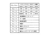
図1に、ICチップのメモリー内に記憶されるデータ構成の一例を示す。図1において、ブロックナンバー1乃至3のエリアは、ICチップ毎に固有のユニーク番号であるUID1〜7や、その他のキー製造時における管理データが書き込まれるエリアである。これらの管理データは、キーの製造時にその製造メーカーによって書き込まれるものであり、一旦書き込まれた番号等を後に改変することはできない。また、後述する遊技機管理機構を管理運営する管理事業者の本店データベース上において、かかるユニーク番号が一括して管理されるものとする。
FIG. 1 shows an example of the data configuration stored in the memory of the IC chip. In FIG. 1, areas with
ブロックナンバー4の遊技機製造メーカーコードは、キーの出荷時(販売時)に管理事業者(販売者)によって書き込まれるものであり、キーが装着される遊技機の製造メーカーを表すものである。なお、一度書き込まれた当該コードは、所定の方法によりロックされてその後に変更することはできない。
The gaming machine manufacturer code of
ブロックナンバー5乃至10の各コードは、キーが装着された遊技機が遊技場のホール等に設置されるときに、上記の管理事業者によって書き込まれるデータであり、一旦書き込まれたデータは、所定の方法でロックされてその後に変更することはできない。 Each code of block numbers 5 to 10 is data written by the management company when a gaming machine equipped with a key is installed in a hall or the like of a game hall. It is locked in this way and cannot be changed afterwards.
なお、図1に示されるICチップメモリー内のデータ構成は、一つの事例を表すものに過ぎず、本発明の実施がかかる事例に限定されるものでないことは言うまでもない。 It should be noted that the data configuration in the IC chip memory shown in FIG. 1 represents only one case, and it goes without saying that the present invention is not limited to such a case.
次に、本発明による遊技機のセキュリティー管理システムについて、パチンコやパチスロ機などの遊技機に上記のキーが装着されて、それに基づくセキュリティー管理が為されまでを時系列的に説明する。 Next, the security management system for gaming machines according to the present invention will be described in time series until the above-described key is attached to a gaming machine such as a pachinko machine or pachislot machine and security management based on the key is performed.
先ず、遊技機の製造メーカーは、キーを一括して管理する管理事業者から、ICチップ固有のユニーク番号(以下、単に“UID”と言う)や遊技機製造メーカーコード等のデータ(図1のブロックナンバー1乃至4のデータ)が既に書き込まれたキーを購入する。そして、自社で製造した遊技機を各地の遊技場に出荷する際に、これらのキーを出荷される遊技機毎に装着する。なお、遊技機単体が全国各地の遊技場に出荷された後、現地において、製造メーカー、或いは管理事業者の監督の下に遊技機へのキーの装着を行うようにしても良い。
First, the manufacturer of the gaming machine receives data such as a unique number unique to the IC chip (hereinafter simply referred to as “UID”) and a gaming machine manufacturer code from a management company that collectively manages keys (FIG. 1). Purchase a key in which
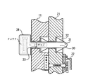
キーが遊技機に装着された状態を図2に示す。同図において、セキュリティーキー30の基体は、円筒軸状の軸部31、軸部に対して放射方向に設けられた可撓性を有する矢羽翼状の係止片32、操作ツマミ部34,及び軸部と操作ツマミ部とを連結する切断部33から成っている。操作ツマミ部34には、例えば、ヘリカルアンテナ等の高周波受信アンテナが内蔵されており、また、切断部33の付近には軸部31に把持される形で上記のICチップが内蔵されている。
FIG. 2 shows a state where the key is attached to the gaming machine. In the figure, the base of the
遊技機フレーム11は、パチンコやパチスロ機等の遊技機の台(フレーム)であり、例えば、釘等が設けられた着脱自在な制御ROM付きの遊技機盤を含む構成であっても良い。また、電子回路ユニット基台21は、遊技機のゲーム動作を総括制御する電子回路ユニット20を担持する部分であり、遊技盤の背面に固定され、電子回路基板が実装された回路基板ケース22を支持すると共に、玉排出通路等を備えた遊技機の本体機構を含む構成であっても良い。なお、遊技機フレーム11の制御ROMと、電子回路ユニット基台21の電子回路基板との間は、コネクタ及びケーブルを介して接続されている。
The
キー30は、遊技機フレーム11及び電子回路ユニット基台21の双方を貫通する開孔部に、その軸部31を挿通することによって遊技機に装着される。キー30の係止は、係止片32の可撓性による部材変形のみを利用して行うようにしても良いし、或るいはキー30の挿通後、軸部31を回転軸としてキーを1/4乃至1/2回転させ、係止片32と開孔部との位置関係の変化を利用して行うようにしても良い。なお、係止片32の形状や、軸部31への取付位置、或いはその取付数等の条件に関しては、図2の記載に限定されるものではない。
The
キー30が一旦、遊技機に装着されると係止片32の作用によって、キー30、遊技機フレーム11、及び電子回路ユニット基台21の三者が固着される。図2からも明らかな如く、キー30の基体は、その切断部33において極端に括れている。それ故、キー装着後に、操作ツマミ部34を掴んで遊技機に装着されたキーを無理に引き抜こうとすると、切断部33にストレスが加わりキー30が同部分において破断される構造となっている。上述の如く、ICチップは、かかる切断部33に埋設内蔵されており、ICチップ自体は脆弱なシリコン基板、或いはセラミック基板で構成されているため、キー30の基体が切断部33の近傍で破断されると、それに伴ってICチップも同時に破壊される。
Once the
以上に説明した如く、キーが一旦遊技機に装着されると、キーに内蔵されているICチップを破壊しない限り、遊技機からキーを取り外せない構造となっている。また、遊技機におけるキーの装着位置は、遊技機のフレームに、同遊技機に内蔵される電子回路ユニットが係止される位置に設けられている。したがって、遊技機に装着されたキーを破断して、キーに内蔵されたICチップを破壊しない限り、遊技機フレームから電子回路ユニットを取り外すことができない。 As described above, once the key is attached to the gaming machine, the key cannot be removed from the gaming machine unless the IC chip built in the key is destroyed. The key mounting position in the gaming machine is provided at a position where an electronic circuit unit built in the gaming machine is locked to the frame of the gaming machine. Therefore, the electronic circuit unit cannot be removed from the gaming machine frame unless the key mounted on the gaming machine is broken and the IC chip built in the key is broken.
次に、キーが装着された遊技機が遊技場に据え付けられるとき(以下、“据付検査時”と言う)の処理を説明する。 Next, a process when the gaming machine equipped with the key is installed in the amusement hall (hereinafter referred to as “at the time of installation inspection”) will be described.
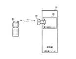
かかる据付検査時に、管理事業者の検査員が操作するハンディーターミナルによって、キーのICチップに図1のブロックナンバー5乃至10のデータが書き込まれる。据付検査時におけるハンディターミナルからキーへのデータ書込みの概念を図3に示す。 At the time of the installation inspection, the data of the block numbers 5 to 10 in FIG. 1 are written on the IC chip of the key by the handy terminal operated by the inspector of the management company. The concept of data writing from the handy terminal to the key at the time of installation inspection is shown in FIG.
図3において、遊技機10は、例えば、パチンコやパチスロ機等の遊技機を表している。電子回路ユニット20は、遊技機10におけるゲーム動作全体を総括制御する部分であり、遊技機10のフレームにキー30によって係止されている。キー30は、前述の如く、メモリー等の各種の電子回路を含むICチップを内蔵している。
In FIG. 3, a
一方、図3のハンディーターミナル40(以下、単に“ターミナル40”と言う)は、例えば、ブルートゥース(Bluetooth)やIEEE802規格等の微弱ないし小電力の電波を利用して、キー30に各種のデータを送信し、或いはキー30から所定のデータを受信する携帯端末装置である。ターミナル40は、キーボードやディスプレイパネル、内部メモリー回路、上記の無線送受信回路、及び各部の制御回路などの各種回路(何れも図示せず)を含んでいる。
On the other hand, the
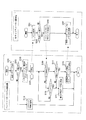
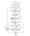
ターミナル40からキー30へのデータの書込み処理を、図4のフローチャートに基づいて説明する。なお、図4の左側の破線に囲まれた部分がターミナル40における動作を示すものであり、その右側の破線に囲まれた部分がキー30の動作を示すものである。 The data writing process from the terminal 40 to the key 30 will be described with reference to the flowchart of FIG. The portion surrounded by the broken line on the left side of FIG. 4 indicates the operation at the terminal 40, and the portion surrounded by the broken line on the right side indicates the operation of the key 30.
先ず、検査員は、ターミナル40の電源投入により同ターミナルを立ち上げると、そのキーボードを介して認証パスワードを入力する。認証パスワードとしては、例えば、ハンディターミナル毎に固有に設定されたハンディーターミナル番号を利用するようにしても良い。なお、かかるハンディターミナル番号も上記事業者によって一括して管理が為されるものとする。また、ハンディターミナル番号以外にも、例えば、ハンディターミナルを操作する検査員について、各個人毎に所定のパスワードを更に設けるようにしても良い。これらのパスワードを設けることによって、例えば、第三者が不正にハンディーターミナルを入手した場合でもその操作ができない仕組みとなる。 First, when the inspector starts up the terminal 40 by turning on the power, the inspector inputs the authentication password via the keyboard. As the authentication password, for example, a handy terminal number uniquely set for each handy terminal may be used. Such handy terminal numbers are also managed collectively by the above-mentioned operators. In addition to the handy terminal number, for example, for an inspector who operates the handy terminal, a predetermined password may be further provided for each individual. By providing these passwords, for example, even if a third party obtains a handy terminal illegally, the operation cannot be performed.
図4のステップS101でターミナル40に認証パスワードが取り込まれると、次のステップS103において、かかるパスワードのチェック処理が為される。チェックの結果、パスワードが不適正であると判定されたときは、ステップS119に移行して、ターミナル40から警報音、或いは警報表示を伴う警告出力が為され、それ以降のターミナル40へのアクセスは禁止される。 When the authentication password is taken into the terminal 40 in step S101 of FIG. 4, the password check process is performed in the next step S103. As a result of the check, if it is determined that the password is inappropriate, the process proceeds to step S119, where an alarm sound or a warning output accompanied by an alarm display is made from the terminal 40, and subsequent access to the terminal 40 is prohibited.
一方、ステップS103でパスワードが適正であると判定された場合、次のステップS105において、キー30にデータを書き込むアプリケーションプログラムの立ち上げ処理が実行される。これによって、ターミナル40の無線通信回路等の各回路の機能が活性化されキー30へのデータ送信が可能となる。 On the other hand, if it is determined in step S103 that the password is appropriate, in step S105, an application program startup process for writing data to the key 30 is executed. As a result, the function of each circuit such as the wireless communication circuit of the terminal 40 is activated, and data transmission to the key 30 becomes possible.
据付検査時においてターミナル40は、据付検査の対象とされる遊技機10、及びそれに装着されたキー30の履歴を当然に把握しており、ターミナル40の内部メモリーには、据付検査の対象とされる各々のキー30の内蔵ICチップに書き込まれたUIDが予めストアされている。ステップS105の立ち上げ処理が完了すると、ターミナル40は、ステップS107で据付検査の対象とされるキー30に対し、当該キーに相当するUIDを内部メモリーから抽出してこれを送信する。
At the time of installation inspection, the terminal 40 naturally grasps the history of the
一方、キー30の側では、ステップS201でターミナル40から送信されたUIDを受信すると、次のステップS203において受信したUIDが適正であるか否かを判定する。具体的には、キー30は、受信したUIDと、ICチップ内メモリーのブロックナンバー1乃至2のエリアに出荷時に書き込まれたUIDとを比較・判定する。
On the other hand, when the key 30 receives the UID transmitted from the terminal 40 in step S201, it determines whether or not the UID received in the next step S203 is appropriate. Specifically, the key 30 compares and determines the received UID and the UID written in the area of
ステップS203において、受信したUIDが不適正、つまり両者が不一致であると判定された場合、キー30はそれ以降の動作を中止する。なお、この場合に、例えば、ターミナル40に、UIDが不適正である旨の通報を行うようにしても良いし、或いは、キー30に設けられた何らかの表示手段に、UIDが不適正である旨を表示させるようにしても良い。一方、ステップS203において、受信したUIDが適正、つまり両者が一致したと判定された場合は次のステップS205に進み、キー30は、ICチップに書き込まれていたUIDをターミナル40に返信する。 If it is determined in step S203 that the received UID is inappropriate, that is, the two do not match, the key 30 stops the subsequent operation. In this case, for example, the terminal 40 may be notified that the UID is inappropriate, or the display means provided on the key 30 may indicate that the UID is inappropriate. May be displayed. On the other hand, if it is determined in step S203 that the received UID is appropriate, that is, the two match, the process proceeds to the next step S205, and the key 30 returns the UID written in the IC chip to the terminal 40.
一方、ターミナル40は、上記のステップS107でキー30へのUID送信を行った後、ステップS109に進み、キー30からUIDの返信が有るか否かを監視して、返信が検知されないときはステップS115に移り、返信監視の待機期間が所定の時間長を経過しているか否かのタイムアウトをチェックする。タイムアウトが発生していなければ、ステップS109に戻り、キー30からのUIDの返信監視を繰り返す。 On the other hand, after transmitting the UID to the key 30 in step S107 described above, the terminal 40 proceeds to step S109 and monitors whether there is a UID reply from the key 30. If no reply is detected, the terminal 40 proceeds to step S109. The process proceeds to S115, and a timeout is checked to determine whether or not the reply monitoring standby period has exceeded a predetermined time length. If no time-out has occurred, the process returns to step S109, and UID reply monitoring from the key 30 is repeated.
ステップS109において、キー30からの返信が検知されると、ターミナル40は次のステップS111に進み、キー30から返信されたUIDが、先に、キー30へ送信したUIDと等しいか否かを判定する。そして、キー30から返信されたUIDが適正である、即ち、通信相手先のキー30が据付検査の対象とするキーであることが確認されると、ステップS113の処理に移行する。
If a reply from the key 30 is detected in step S109, the terminal 40 proceeds to the next step S111, and determines whether or not the UID returned from the key 30 is equal to the UID previously transmitted to the key 30. To do. When it is confirmed that the UID returned from the key 30 is appropriate, that is, the
ステップS113において、ターミナル40は、検査員がキーボードから入力した以下のデータを取り込み、これらのデータに所定の暗号化処理を施した後、これをキー30に送信する。 In step S113, the terminal 40 captures the following data input from the keyboard by the inspector, performs a predetermined encryption process on the data, and transmits the data to the key 30.
(1)ホール番号
(2)遊技機台番号
(3)検査日
(4)管理エリアコード
(5)管理者コード
(6)書込みハンディーターミナル番号
上記の各データを簡単に説明すれば、(1)はキー30が装着された遊技機10が設置されている遊技場内のホール番号を示すものであり、(2)はホール内、若しくは遊技場内における当該遊技機の台番号を表す。(3)はキー30へのデータ書込みが行われた期日、即ち据付検査の行われた日を示すものであり、(4)は当該遊技機が設置された遊技場の地域を示す管理エリアコードを示すものである。また、(5)はセキュリティー管理システムを運営する管理者の略号を示すものであり、(6)は書込みを行ったハンディーターミナルの機器認証番号を示すものである。なお、管理エリアコードや管理者コードは、前述の管理事業者によって一括して管理されるものとする。
(1) Hall number (2) Gaming machine stand number (3) Inspection date (4) Management area code (5) Administrator code (6) Writing handy terminal number If each of the above data is briefly explained, (1) Indicates the hall number in the game hall where the
以上の各データは、据付検査が為される遊技機10にとって固有のものであり、かつ同遊技機が遊技場に設置された後の管理情報となるので、以後“設置後管理データ”と称するものとする。なお、ターミナル40は、暗号化された設置後管理データをキー30に送信すると共に、当該キーのUIDとリンクさせて、同データをターミナル40の内部メモリーに保存する。
Each piece of data described above is unique to the
一方、キー30側では、ターミナル40から設置後管理データを受信すると、ステップS207において、これらのデータをICチップ内の所定メモリーエリアに記憶する。因みに、これらの設置後管理データが記憶されるメモリーエリアは、図1に示されるブロックナンバー5乃至10の領域に相当する。 On the other hand, when the post-installation management data is received from the terminal 40 on the key 30 side, these data are stored in a predetermined memory area in the IC chip in step S207. Incidentally, the memory area in which the post-installation management data is stored corresponds to the areas of block numbers 5 to 10 shown in FIG.
なお、キー30のICチップにおいて設置後管理データの書込みは、1回のみで禁止される構成となっている。かかる構成は、例えば、フューズROM(Read Only Memory)のような書込みセルの溶断によって書き込まれた情報を担保するハードウェアで実現しても良いし、或いは、ICチップ内のマイクロプロセッサによる所定のソフトウェア処理によって実現するようにしても良い。これによって、一旦、キー30に書き込まれた設置後管理データが変更されたり、新たな設置後管理データが上書きされる危険を回避できる。 In the IC chip of the key 30, writing of management data after installation is prohibited only once. Such a configuration may be realized by hardware such as a fuse ROM (Read Only Memory) that secures information written by fusing write cells, or predetermined software by a microprocessor in an IC chip. It may be realized by processing. As a result, it is possible to avoid the risk that the post-installation management data once written in the key 30 is changed or new post-installation management data is overwritten.
ICチップのメモリー内に所定の設置後管理データが書き込まれるとキー30における据付検査時の処理は終了する。なお、キー30は、データ書込み処理の終了をターミナル40に通知するようにしても良いし、或いは、キー30に設けられた何らかの表示手段に、処理が終了した旨を表示させるようにしても良い。
When management data after predetermined installation is written in the memory of the IC chip, the processing at the time of installation inspection in the key 30 ends. Note that the key 30 may notify the
一方、ターミナル40側では、ステップS113において、キー30への設置後管理データの送信、及び内部メモリーへの保存を終了させると、1つのキー30への処理を終了させる。
On the other hand, on the terminal 40 side, when the transmission of the management data after installation to the key 30 and the storage in the internal memory are terminated in step S113, the processing for one
なお、ステップS111においてキー30から返信されたUIDが不適正であると判定された場合、または、ステップS115で、キー30から返信がなくタイムアウトが判定された場合、ターミナル40は、ステップS117に移行する。そして、据付検査対象の遊技機に装着されたキーが不適正なものである旨の警告表示を行った後、当該キーへの処理を終了させ、次の据付検査対象の遊技機キーに処理を移行させる。 If it is determined in step S111 that the UID returned from the key 30 is inappropriate, or if it is determined in step S115 that there is no response from the key 30 and a timeout is determined, the terminal 40 proceeds to step S117. To do. Then, after displaying a warning that the key attached to the gaming machine subject to installation inspection is improper, the processing for that key is terminated, and the next gaming machine key subject to installation inspection is processed. Transition.
なお、ターミナル40は、据付検査の対象とされる全ての遊技機10に装着されているキー30に対して、以上に説明した設置後管理データの書込み処理を実行する。
The terminal 40 executes the post-installation management data writing process described above for the
次に、管理事業者の所轄支店におけるハンディターミナルからデータ保存用コンピュータへの設置後管理データの転送、及び同データの保存・表示について説明する。 Next, transfer of the management data after installation from the handy terminal in the branch office of the management company to the data storage computer, and storage / display of the data will be described.
上記の据付検査が終了すると、検査員は、据付検査が行われた遊技場を管轄する管理事業者の支店にハンディターミナルを持ち帰る。前述の如く、ハンディターミナルは、その内部にメモリーを有しており、据付検査時に書込まれた遊技機毎の設置後管理データが暗号化されて同メモリー内に蓄積されている。ハンディターミナルに蓄積されるデータ量は、その内蔵メモリーの容量によって左右されるが、データ処理の便宜上から、例えば、1台のハンディターミナルに蓄積可能なデータ量を遊技機3000台程度に定めるようにしても良い。なお、全ての設置後管理データは、各々のキーのUIDとリンクしてメモリー内に蓄積されていることは言うまでもない。 When the installation inspection is completed, the inspector takes the handy terminal back to the branch of the management company having jurisdiction over the amusement hall where the installation inspection is performed. As described above, the handy terminal has a memory therein, and post-installation management data for each gaming machine written at the time of installation inspection is encrypted and stored in the memory. The amount of data stored in the handy terminal depends on the capacity of the built-in memory, but for the convenience of data processing, for example, the amount of data that can be stored in one handy terminal is set to about 3000 gaming machines. May be. Needless to say, all post-installation management data is stored in the memory linked to the UID of each key.
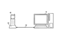
所轄支店に持ち帰ったハンディターミナルからは、図5に示される如く、その内蔵メモリーに蓄積されたデータが同支店のデータ保存用コンピュータに転送される。 As shown in FIG. 5, the data stored in the built-in memory is transferred from the handy terminal brought back to the branch office to the data storage computer of the branch office.
図5において、通信ユニット50は、ターミナル40の内蔵メモリーに蓄積された設置後管理データを読み出して、これをデータ保存用コンピュータ70(以下、単に“コンピュータ70”と言う)に転送する通信ユニットであり、通信ケーブル60を介してコンピュータ70に接続されている。また、コンピュータ70は、例えば、デスクトップ型のパーソナルコンピュータであり、本体のCPU、キーボード、ディスプレイ、HDD等の記録媒体から成る記憶部、及び各種の通信ポートを備えている。なお、ターミナル40から転送された遊技機毎の設置後管理データは、かかる記憶部にデータベースとして保存される。
In FIG. 5, a
なお、図5に示される事例では、ターミナル40とコンピュータ70とを、通信ユニット50及び通信ケーブル60を介して有線接続しているが、本発明は、かかる事例に限定されるものではなく、例えば、前述したキー30へのデータ書込み時のように、無線通信媒体を用いて両者を接続するようにしても良い。
In the case shown in FIG. 5, the terminal 40 and the
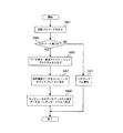
次に、ターミナル40からコンピュータ70へのデータの転送処理を、図6のフローチャートに基づいて説明する。
Next, data transfer processing from the terminal 40 to the
コンピュータ70の電源が投入されてその動作が開始されると、先ず、ステップS301において認証パスワードの取込処理がなされる。すなわち、コンピュータ70の操作者は、当該操作者、或いはコンピュータ70について予め設定された認証用のバスワードをコンピュータ70のキーボードを介して入力すると、コンピュータ70がこれを取り込む。なお、パスワードとして文字コードではなく、例えば、予め登録された操作者の指紋や血流等の個人認識情報を用いるようにしても良い。この場合、コンピュータ70は、指紋スキャナーなどの所定のセンサー機器を用いてこれらの情報を取り込むことになる。かかる処置を講ずることにより、第三者が不正にコンピュータ70を操作してコンピュータ内のデータベースにアクセスすることを防ぐことができる。
When the
ステップS301で認証パスワードが上記いずれかの形で取り込まれると、コンピュータ70は、ステップS303に移り、取り込んだパスワードのチェックを行う。ステップS303においてバスワードが不適正であると判定された場合、コンピュータ70は、ステップS317に移行してパスワードが不正である旨の警告処理を実行して図6の処理を終了させる。不正警告処理は、例えば、ディスプレイ上に不正アクセスが行われている旨を表示するメッセージを出力するようにしても良いし、或いは、スピーカやブザー等から不正アクセスを示す警告音を出力しても良い。
When the authentication password is fetched in any of the above forms in step S301, the
一方、ステップS303においてパスワードが適正であると判定された場合、コンピュータ70は、ステップS305に進み、ターミナル40からのデータ取り込みアプリケーションプログラムの立ち上げ処理を実行する。これによって、コンピュータ70からは、通信ケーブル60及び通信ユニット50を介して、ターミナル40にデータの取込指令が送信され、これを受信したターミナル40は、そのメモリー内に蓄積されているデータの転送を準備する。
On the other hand, if it is determined in step S303 that the password is appropriate, the
なお、セキュリティシステムの完全性を期すべく、例えば、ターミナル40からデータを転送する際に、コンピュータ70からターミナル40にそのハンディターミナル番号を送信して、ターミナル40側においてもハンディターミナル番号の認証処理を行うようにしても良い。
In order to ensure the integrity of the security system, for example, when data is transferred from the terminal 40, the handy terminal number is transmitted from the
ステップS305の処理が完了すると、コンピュータ70は、次のステップS307に進み、ターミナル40に蓄積されたデータの転送を開始させる。これによって、ターミナル40の内蔵メモリーに蓄積されていた各遊技機毎の設置後管理データが、全てコンピュータ70に転送される。
When the process of step S305 is completed, the
ステップS307が終了すると、コンピュータ70はステップS309において、ターミナル40から転送されたデータを、その記憶部の所定エリア内にデータベースとして格納する。すなわち、ステップS309が終了した時点で、コンピュータ70の記憶部には、据付検査が終了した遊技機に関する設置後管理データが、各遊技機に装着されたキー30のUIDに関連づけされ保存される。このようにしてコンピュータ70の記憶部に形成されたデータベースを利用することにより、所轄支店では、その管内に設置されている遊技機の動向を容易に把握することができる。
When step S307 ends, in step S309, the
ところで、コンピュータ70のデータベース上に保存された各遊技機の設置後管理データは、前述の如く、暗号化されたままの状態である。それ故、これらのデータをそのままコンピュータ70のディスプレイ上に表示しても、操作者はその内容を理解することができない。そこで、保存データをディスプレイ上に操作者に理解可能な形で表示する解読表示処理が必要となり、これを図6のフローチャートに基づいて以下に説明する。
By the way, the post-installation management data of each gaming machine stored on the database of the
ステップS309のデータ保存処理が終了すると、コンピュータ70はステップS311において、操作者からデータベースの表示要求が為されているか否かを判定する。かかる要求が為されていないときは、コンピュータ70はその処理を終了させる。一方、表示要求があるときは、コンピュータ70は、ステップS313に進んで再度認証パスワードの取込み並びにチェック処理を実行する。なお、同処理については、前述のステップS301、S303と同様であるためその説明を省略する。
When the data storage process in step S309 ends, the
ステップS313において、パスワードが適正であると判定された場合は、コンピュータ70は、ステップS315に進んで、データベース上に保存された設置後管理データに所定の暗号解読処理を施して、解読後のデータをそのディスプレイ上に表示する。一方、ステップS313で、パスワードが不適正であると判定された場合は、コンピュータ70は、ステップS317の不正警告処理を実行して図6に示される処理を終了させる。
If it is determined in step S313 that the password is proper, the
次に、遊技機の確認検査時における処理について説明を行う。なお、遊技機の確認検査とは、据付検査を経て各遊技場に据え付けられた遊技機に不正行為が加えられていないかをチェックする検査のことである。確認検査では、先ず、確認検査の対象とされる遊技機に関する据付検査時の設置管理後データを、所轄支店のデータ保存用コンピュータから当該遊技機の据付検査時に使用されたハンディーターミナルにロードする。その後、管理事業者の検査員が、このハンディーターミナルを遊技場に持参して、確認検査の対象となる遊技機のセキュリティーキーから設置後管理データを読み取り、これを据付検査時のデータと照合することにより行う。 Next, the process at the time of the check inspection of the gaming machine will be described. Note that the gaming machine confirmation inspection is an inspection for checking whether or not fraudulent acts have been applied to the gaming machines installed in each game hall through the installation inspection. In the confirmation inspection, first, the post-installation management data at the time of the installation inspection relating to the gaming machine to be subjected to the confirmation inspection is loaded from the data storage computer of the branch office to the handy terminal used at the time of the installation inspection of the gaming machine. After that, the inspector of the management company brings this handy terminal to the amusement hall, reads the management data after installation from the security key of the gaming machine subject to confirmation inspection, and compares this with the data at the time of installation inspection By doing.
先ず、確認検査時の所轄支店における処理について前述の図5を参照しつつ説明を行う。確認検査を行うためには、上記の如く、検査対象とされる各遊技機に関する設置後管理データをコンピュータ70からターミナル40にロードする必要がある。それ故、ターミナル40を、通信ユニット50、及び通信ケーブル60を介してコンピュータ70に接続する。なお、以上の各機器についての説明は、既に記述しているため省略する。
First, processing at the branch office at the time of confirmation inspection will be described with reference to FIG. In order to perform the confirmation inspection, it is necessary to load post-installation management data regarding each gaming machine to be inspected from the
次に、コンピュータ70からターミナル40へのデータのロード処理を、図7のフローチャートに基づいて説明する。なお、図7におけるステップS401、S403、及びS411に関しては、図6のステップS301、S303、及びS317の各ステップと同様であるためその説明を省略し、図7のステップS405以下を説明する。
Next, data loading processing from the
すなわち、ステップS403において、パスワードが適正であると判定されると、コンピュータ70は、ステップS405に進み、データの表示及び転送のアプリケーションプログラムを立ち上げる。確認検査処理の正確を期すべく、次のステップS407で、コンピュータ70は、確認検査の対象とされる遊技機の設置後管理データを記憶部のデータベースから抽出して暗号解読を施した後、これをディスプレイ上に表示する。以上の処理が終了すると、コンピュータ70は、ステップS409に移り、そのデータベースからターミナル40へデータを転送する。なお、ターミナル40では、転送されたデータ、即ち、確認検査の対象とされる各遊技機の設置後管理データを、遊技機の各々に装着されたキー30に含まれるICチップ毎のUIDを基準にして内蔵メモリーにストアする。
That is, if it is determined in step S403 that the password is appropriate, the
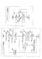
次に、遊技場における確認検査処理の様子を図8のフローチャートに基づいて説明するる。なお、図8の場合もハンディーターミナル側処理のステップS501、S503、及びS519に関しては、図4のステップS101、S103、及びS119の各ステップと同様であるためその説明を省略する。 Next, the state of the confirmation inspection process in the game hall will be described based on the flowchart of FIG. In the case of FIG. 8 as well, steps S501, S503, and S519 of the handy terminal side processing are the same as the steps S101, S103, and S119 of FIG.
したがって、図8に関しては、ハンディーターミナル側処理のステップS505から説明を始める。即ち、ターミナル40は、ステップS503でパスワードが適正であると判定されるとステップS505に進み、データ照合プログラムを立ち上げ、さらに、次のステップS505で、確認検査の対象とされる遊技機10のキー30に対して、そのICチップのUIDを送信する。
Therefore, with respect to FIG. 8, the description starts from step S505 of the handy terminal side processing. That is, if it is determined in step S503 that the password is appropriate, the terminal 40 proceeds to step S505 to start up a data collation program, and in the next step S505, the
セキュリティーキー側では、ステップS601でターミナル40から送信されたUIDを受信すると、次のステップS603において受信したUIDが適正であるか否かを判定する。具体的には、キー30は、受信したUIDと、ICチップ内メモリーのブロックナンバー1乃至2のエリアに出荷時に書き込まれたUIDとを比較・判定する。
On the security key side, when the UID transmitted from the terminal 40 is received in step S601, it is determined whether or not the UID received in the next step S603 is appropriate. Specifically, the key 30 compares and determines the received UID and the UID written in the area of
ステップS603において、受信したUIDが不適正、つまり両者が不一致であると判定された場合、キー30はそれ以降の動作を中止する。なお、この場合に、例えば、ターミナル40に、UIDが不適正である旨の通報を行うようにしても良いし、或いは、キー30に設けられた何らかの表示手段に、UIDが不適正である旨を表示させるようにしても良い。一方、ステップS603において、受信したUIDが適正、つまり両者が一致したと判定された場合は次のステップS605に進み、キー30は、ICチップに書き込まれていた設置後管理データをターミナル40に返信する。 If it is determined in step S603 that the received UID is inappropriate, that is, the two do not match, the key 30 stops the subsequent operation. In this case, for example, the terminal 40 may be notified that the UID is inappropriate, or the display means provided on the key 30 may indicate that the UID is inappropriate. May be displayed. On the other hand, if it is determined in step S603 that the received UID is appropriate, that is, the two match, the process proceeds to the next step S605, and the key 30 returns the post-installation management data written in the IC chip to the terminal 40. To do.
一方、ターミナル40は、上記のステップS507でキー30へのUID送信を行った後、ステップS509に進み、キー30からデータの返信が有るか否かを監視して、返信が検知されないときはステップS515に移り、返信監視の待機期間が所定の時間長を経過しているか否かのタイムアウトをチェックする。そして、タイムアウトが発生していなければ、ステップS509に戻り、キー30からのデータの返信監視を繰り返す。
On the other hand, after transmitting the UID to the key 30 in the above step S507, the terminal 40 proceeds to step S509 and monitors whether there is a data reply from the key 30, and if no reply is detected, the
ステップS509において、キー30からの返信が検知されると、ターミナル40は次のステップS511に進み、キー30から返信されたデータと内蔵メモリーにストアされているデータとの照合を行う。すなわち、確認検査対象とされる遊技機のICチップから直接読み込んだ設置後管理データと、所轄支店のデータベースからロードされた当該遊技機に関する設置後管理データとを照合するわけである。キーの偽造や電子回路ユニットの交換等の不正行為が為されていなければ当然に両者のデータは一致し、その遊技機は適正なものであるとの確認が為されて、当該遊技機についての確認検査を終了する。 When a reply from the key 30 is detected in step S509, the terminal 40 proceeds to the next step S511, and collates the data returned from the key 30 with the data stored in the built-in memory. That is, the post-installation management data directly read from the IC chip of the gaming machine that is the subject of confirmation inspection is compared with the post-installation management data related to the gaming machine loaded from the database of the responsible branch. If there is no fraudulent act such as forgery of keys or replacement of electronic circuit units, both data will of course match and the gaming machine will be confirmed to be appropriate. The confirmation inspection ends.
一方、ステップS511においてキー30から返信された設置後管理データが不適正であると判定された場合、または、ステップS515で、キー30から返信がなくタイムアウトが判定された場合、ターミナル40は、ステップS517に移行する。そして、検査対象の遊技機に装着されたキーが不適正なものである旨の警告表示を行った後、当該キーへの処理を終了させ、次の確認検査対象の遊技機キーに処理を移行させる。 On the other hand, if it is determined in step S511 that the post-installation management data returned from the key 30 is inappropriate, or if there is no response from the key 30 and a timeout is determined in step S515, the terminal 40 The process proceeds to S517. Then, after displaying a warning that the key attached to the gaming machine to be inspected is inappropriate, the processing for that key is terminated, and the processing shifts to the next gaming machine key to be checked Let
なお、ターミナル40は、確認検査の対象とされる全ての遊技機10に装着されているキー30に対して、以上に説明した設置後管理データの照合処理を実行する。
Note that the terminal 40 executes the post-installation management data collation process described above for the
次に、管理事業者の本店に設置された中央管理データサーバーによる、各遊技機の集中管理について図9を参照しつつ説明を行う。 Next, centralized management of each gaming machine by the central management data server installed at the head office of the management company will be described with reference to FIG.
図9において、コンピュータ70は、各地の所轄支店に設置されたデータ保存用のコンピュータを表す。中央管理データサーバー90は、遊技機管理機構を担う管理事業者の本店に設置されたデータサーバーであり、各地の所轄支店のコンピュータ70に保存されているデータベースを一括して集中管理するものである。また、通信ネットワーク80は、例えば、NTTやその他の通信事業者が運営管理する専用回線等の通信ネットワークである。各所轄支店のコンピュータ70は、通信ネットワーク80を介して本店の中央管理データサーバー90に接続されている。
In FIG. 9, a
各支店のコンピュータ70と本店の中央管理データサーバー90との間において、予め所定の認証コードを定めておき双方が相互認証を行いつつ、各支店のコンピュータ70のデータベースに格納された各遊技機の設置後管理データを本店の中央管理データサーバー90に転送する。これによって、全国各地の遊技場に設置された遊技機の動向を本店の中央管理データサーバー90により、一括して集中管理することが可能となる。
A predetermined authentication code is set in advance between the
なお、図9に示される支店や本店の数は、説明の便宜上のものであり、本発明の実施がかかる事例に限定されるものでないことは言うまでもない。 Note that the numbers of branches and head offices shown in FIG. 9 are for convenience of explanation, and it goes without saying that the implementation of the present invention is not limited to such cases.
以上に説明したように、本発明による遊技機のセキュリティー管理システムによれば、遊技場における遊技機の据付検査及び確認検査の方式を統一することが可能となり、全国各地の遊技場に設置された遊技機を中央で集中管理することができる。また、各地の支店間における遊技機の移動も容易に把握することが可能となり、遊技機に対する不正行為の発見も容易となる。 As described above, according to the gaming machine security management system according to the present invention, it is possible to unify the game machine installation inspection and confirmation inspection methods in the game arcade, and it is installed in game halls throughout the country. Centrally manage gaming machines in the center. In addition, it is possible to easily grasp the movement of gaming machines between branch offices in various places, and it becomes easy to find fraudulent acts on gaming machines.
10 遊技機
11 遊技機フレーム
20 電子回路ユニット
21 電子回路ユニット基台
22 電子回路基板ケース
30 セキュリティーキー(セキュリティーキー基体)
31 軸部
32 係止片
33 切断部
34 操作ツマミ部
40 ハンディターミナル
50 通信ユニット
60 通信ケーブル
70 データ保存用コンピュータ
80 通信ネットワーク
90 中央管理データサーバ
10
31
Claims (9)
前記セキュリティーキーとの間で前記データの授受を行うハンディターミナルと、
前記ハンディターミナルとの間で前記ICチップ毎に書き込まれたデータの授受を行うコンピュータと、
通信ネットワークを介して前記コンピュータとの間で前記ICチップ毎に書き込まれたデータの授受を行って、前記セキュリティーキーが設けられた遊技機の各々を集中して管理するデータサーバーと、を含むことを特徴とする遊技機のセキュリティー管理システム。 A security key provided for each gaming machine, which has a built-in IC chip including a memory for storing data and can freely write and read data including post-installation management data unique to each gaming machine;
A handy terminal that exchanges the data with the security key;
A computer for exchanging data written for each IC chip with the handy terminal;
A data server that exchanges data written for each IC chip with the computer via a communication network and centrally manages each of the gaming machines provided with the security key. A gaming machine security management system characterized by
前記ICチップへ書き込まれた設置管理後データ若しくは前記コンピュータから読み出した設置管理後データを前記セキュリティーキー毎に記憶する記憶手段と、
相互認証の確認されたセキュリティーキーのICチップから読み出した設置管理後データと前記コンピュータから読み出して前記記憶手段に記憶された設置管理後データとを照合する照合手段と、を含むことを特徴とする請求項1に記載のセキュリティー管理システム。 The handy terminal is
Storage means for storing after installation management data written to the IC chip or after installation management data read from the computer for each security key;
And a verification unit for verifying the post-installation management data read from the IC chip of the security key whose mutual authentication is confirmed and the post-installation management data read from the computer and stored in the storage unit. The security management system according to claim 1.
Priority Applications (1)
| Application Number | Priority Date | Filing Date | Title |
|---|---|---|---|
| JP2004120066A JP2005296489A (en) | 2004-04-15 | 2004-04-15 | Security management system of game machine |
Applications Claiming Priority (1)
| Application Number | Priority Date | Filing Date | Title |
|---|---|---|---|
| JP2004120066A JP2005296489A (en) | 2004-04-15 | 2004-04-15 | Security management system of game machine |
Publications (1)
| Publication Number | Publication Date |
|---|---|
| JP2005296489A true JP2005296489A (en) | 2005-10-27 |
Family
ID=35328737
Family Applications (1)
| Application Number | Title | Priority Date | Filing Date |
|---|---|---|---|
| JP2004120066A Pending JP2005296489A (en) | 2004-04-15 | 2004-04-15 | Security management system of game machine |
Country Status (1)
| Country | Link |
|---|---|
| JP (1) | JP2005296489A (en) |
Cited By (2)
| Publication number | Priority date | Publication date | Assignee | Title |
|---|---|---|---|---|
| JP2008078824A (en) * | 2006-09-19 | 2008-04-03 | Ricoh Co Ltd | Electronic apparatus and image forming apparatus |
| JPWO2017047505A1 (en) * | 2015-09-15 | 2018-02-22 | 株式会社村田製作所 | Key with wireless communication device and key lock with wireless communication device |
-
2004
- 2004-04-15 JP JP2004120066A patent/JP2005296489A/en active Pending
Cited By (2)
| Publication number | Priority date | Publication date | Assignee | Title |
|---|---|---|---|---|
| JP2008078824A (en) * | 2006-09-19 | 2008-04-03 | Ricoh Co Ltd | Electronic apparatus and image forming apparatus |
| JPWO2017047505A1 (en) * | 2015-09-15 | 2018-02-22 | 株式会社村田製作所 | Key with wireless communication device and key lock with wireless communication device |
Similar Documents
| Publication | Publication Date | Title |
|---|---|---|
| JP4656034B2 (en) | Storage device access system | |
| EP1388989B1 (en) | Digital contents issuing system and digital contents issuing method | |
| US7357329B2 (en) | IC card, terminal device, and data communication method | |
| US8257171B2 (en) | Secure mode control in wagering game systems | |
| CN102043978A (en) | IC chip, information processing apparatus, system, method and program | |
| JP2002014838A (en) | LSI, electronic device mounted with LSI, debugging method, and LSI debugging device | |
| JP5839655B2 (en) | GAME SYSTEM AND GAME DEVICE | |
| JP2000233057A (en) | Monitoring system for gaming machine control chips | |
| JPH11123270A (en) | Game program supply system | |
| JP4289595B2 (en) | Management system for games | |
| JP2006227930A (en) | Operation authentication system for gaming machine and gaming machine | |
| US8632398B2 (en) | Wagering game machine cabinet license compliance | |
| JP4289594B2 (en) | Management system for games | |
| JP5828667B2 (en) | GAME SYSTEM AND GAME DEVICE | |
| JP2010160765A (en) | System lsi and debugging method thereof | |
| JP2009082733A (en) | Game processing unit | |
| JPH11169547A (en) | Gaming device monitoring device | |
| JP5723668B2 (en) | Game system | |
| JP5386860B2 (en) | Payment system, payment processing apparatus, validity verification apparatus, validity verification request processing program, validity verification processing program, and validity verification method | |
| JP4641043B2 (en) | Game machine | |
| JP4801965B2 (en) | Gaming machine monitoring system and gaming machine | |
| JP4215843B2 (en) | Gaming device monitoring device | |
| JP5941624B2 (en) | GAME SYSTEM, WRITE DEVICE, AND GAME DEVICE MANUFACTURING METHOD | |
| JP5828666B2 (en) | GAME SYSTEM AND GAME DEVICE | |
| JP5828668B2 (en) | GAME SYSTEM, AUTHENTICATION DEVICE, AND GAME DEVICE |
Legal Events
| Date | Code | Title | Description |
|---|---|---|---|
| A131 | Notification of reasons for refusal |
Free format text: JAPANESE INTERMEDIATE CODE: A131 Effective date: 20080617 |
|
| A521 | Written amendment |
Free format text: JAPANESE INTERMEDIATE CODE: A523 Effective date: 20080806 |
|
| A131 | Notification of reasons for refusal |
Free format text: JAPANESE INTERMEDIATE CODE: A131 Effective date: 20081014 |
|
| A02 | Decision of refusal |
Free format text: JAPANESE INTERMEDIATE CODE: A02 Effective date: 20090303 |