JP2005296476A - Leveling lifter - Google Patents
Leveling lifter Download PDFInfo
- Publication number
- JP2005296476A JP2005296476A JP2004119769A JP2004119769A JP2005296476A JP 2005296476 A JP2005296476 A JP 2005296476A JP 2004119769 A JP2004119769 A JP 2004119769A JP 2004119769 A JP2004119769 A JP 2004119769A JP 2005296476 A JP2005296476 A JP 2005296476A
- Authority
- JP
- Japan
- Prior art keywords
- lifter
- cylinder unit
- piston cylinder
- riding
- drive mechanism
- Prior art date
- Legal status (The legal status is an assumption and is not a legal conclusion. Google has not performed a legal analysis and makes no representation as to the accuracy of the status listed.)
- Pending
Links
Images
Landscapes
- Invalid Beds And Related Equipment (AREA)
Abstract
【課題】災害時のような停電時にも確実に利用することができ、しかも安価で、既存の建物にも容易に設置できる段差解消リフターを提供する。
【解決手段】 人、車椅子、物品等が乗る乗り板(15)と、この乗り板(15)を上下方向に駆動するピストンシリンダユニット(20)と、乗り板(15)とピストンシリンダユニット(20)との間に介在されている駆動機構とから構成する。駆動機構をスタンド(2)に案内されて上下動する駆動体(10)と、この駆動体(10)の下端部から水平方向に前方に延び、延びた部分に乗り板(15)が取り付けられるようになっている一対の支持アーム(14、14)とから構成する。ピストンシリンダユニット(20)には水道水を給排する。
【選択図】 図1
A level difference elimination lifter that can be used reliably even in the event of a power failure such as a disaster, is inexpensive, and can be easily installed in an existing building.
A riding board (15) on which a person, a wheelchair, an article or the like rides, a piston cylinder unit (20) for driving the riding board (15) in the vertical direction, a riding board (15), and a piston cylinder unit (20) ) And a drive mechanism interposed therebetween. A drive body (10) that moves up and down as the drive mechanism is guided by the stand (2), and extends forward in the horizontal direction from the lower end of the drive body (10), and a ride plate (15) is attached to the extended portion. A pair of support arms (14, 14) is configured. Tap water is supplied to and discharged from the piston cylinder unit (20).
[Selection] Figure 1
Description
本発明は、段差解消リフターに関し、さらに具体的には人、車椅子、荷物等を載せる乗り板が第1の位置と、この第1の位置より所定量だけ高い第2の位置との間を上下方向に駆動さるれるようになっている段差解消リフターに関するものである。 The present invention relates to a level difference lifting lifter, and more specifically, between a first position and a second position where a riding board on which a person, a wheelchair, a luggage, etc. is placed is higher by a predetermined amount than the first position. The present invention relates to a step elimination lifter that is driven in a direction.
上下方向に大きな間隔のある建物には、例えば電気モータで駆動されるエレベータ、エスカレータ等が設けられている。したがって、高齢者も障害者もエスカレータ等を利用することにより、上下の室の間あるいは場所間に自由に移動できる。一方、上下方向の間隔の小さい建物には複数段からなる階段が設けられている。さらには、1段の段差がある建物も見受けられる。このような階段状の段差は、健常者にとっては意識にも昇らないが、妊婦、高齢者、障害者、大きな荷物を搬送するとき等には大きな障害となる。そこて、段差のない床構造の家も建設されつつあるが、既存の建物の段差は依然として残っている。 For example, an elevator or an escalator driven by an electric motor is provided in a building having a large interval in the vertical direction. Therefore, both elderly and disabled persons can freely move between upper and lower rooms or between places by using an escalator or the like. On the other hand, a building having a small vertical interval is provided with a plurality of steps. In addition, there are buildings with one step. Such a stepped step does not raise the consciousness for a healthy person, but it becomes a major obstacle when pregnant women, elderly people, disabled people, and transporting large luggage. Therefore, a house with a floor structure without steps is being built, but the steps of the existing building still remain.
そこで、特許文献1により簡易昇降装置が提案されている。この簡易昇降装置は、ケージと、このケージを吊り下げているチエーンとからなっている。そして、チエーンは、階段の下端部と上端部に設けられているスプロケットに掛け回され、例えば上方のスプロケットが回転モータにより駆動されるようになっている。したがって、車椅子使用者がケージが下端部にあるとき乗り込み、そして例えばスイッチを押すと、ケージは上端部まで自動的に駆動される。これにより、上端部まで移動することができる。 Therefore, Patent Document 1 proposes a simple lifting device. This simple lifting device includes a cage and a chain that suspends the cage. The chain is hung around sprockets provided at the lower and upper ends of the staircase, and the upper sprocket is driven by a rotary motor, for example. Thus, when a wheelchair user gets in when the cage is at the lower end and presses a switch, for example, the cage is automatically driven to the upper end. Thereby, it can move to an upper end part.
上記従来の簡易昇降装置は、ケージを備え、このケージが電動モータにより上下方向に駆動されるようになっているので、車椅子使用者も介助人の助けを借りることなく、比較的長い階段あるいは斜面を昇降することができ、複数段からなる階段に適用されると、それなりの利点は認められる。しかしながら、規模が大きすぎ、高価になることが予想される。また、このような大きな簡易昇降装置を室内に設けると、建物内の美観が一変することもあり得る。このような理由により、階段状の段差が1個あるいは2個程度の段差がある住宅、小規模建物等においては実施するはできない。特に、規模が大きすぎて既存の住宅等に設置することはできない。また、従来の簡易昇降装置は、災害時にサービスが途絶える可能性の高い電動モータで駆動されるようになっているので、一番必要とされる災害時に、障害者、車椅子使用者等が利用できないという問題もある。
本発明は、上記したような従来の問題点を解決したリフターを提供しようとするもので、具体的には限定するものではないが、上下方向に1、2段の比較的高低差の小さい建物内に適用して好適な段差解消リフターを提供することを目的としている。また、災害時のような停電時にも確実に利用することができ、しかも安価で、既存の建物にも容易に設置できる段差解消リフターを提供することも目的としている。
The conventional simple elevating device includes a cage, and the cage is driven in the vertical direction by an electric motor. Therefore, a wheelchair user can obtain a relatively long stairs or slope without assistance from an assistant. When applied to a multi-step staircase, a certain advantage is recognized. However, it is expected to be too large and expensive. In addition, when such a large simple lifting device is provided in a room, the aesthetics in the building may change completely. For this reason, it cannot be implemented in a house or small building having one or two stepped steps. In particular, it is too large to be installed in existing houses. In addition, since the conventional simple lifting device is driven by an electric motor that is highly likely to lose service in the event of a disaster, it cannot be used by persons with disabilities, wheelchair users, etc. at the time of the most necessary disaster There is also a problem.
The present invention is intended to provide a lifter that solves the above-described conventional problems, and is not specifically limited, but is a building having a relatively small height difference of one or two steps in the vertical direction. It is an object of the present invention to provide a level difference elimination lifter that is suitable for application inside. Another object of the present invention is to provide a step-lifting lifter that can be used reliably in the event of a power failure such as a disaster, is inexpensive, and can be easily installed in an existing building.
本発明は、上記目的を達成するために、人、車椅子、物品等が乗る乗り板は原動機により上下方向に駆動されるが、この原動機には水圧望ましくは水道水の水圧で作動するピストンシリンダユニットが適用される。さらに限定すると、乗り板はピストンシリンダユニットと原動機との間に介在されている駆動機構を介して上下方向に駆動されるように構成される。
かくして、請求項1に記載の発明は、人、車椅子、物品等が乗る乗り板と、該乗り板を上下方向に駆動する原動機と、前記乗り板と前記原動機との間に介在されている駆動機構とからなり、前記乗り板が、前記原動機により前記駆動機構を介して、第1の位置と、この第1の位置より所定量だけ高い第2の位置との間を上下方向に駆動さるようになっている段差解消リフターであって、前記原動機は、水圧で作動するピストンシリンダユニットから構成されている。
請求項2に記載の発明は、請求項1に記載のリフターにおいて、駆動機構がスタンドに案内されて上下動する駆動体と、該駆動体の下端部から水平方向に前方に延び、延びた部分に乗り板が取り付けられるようになっている支持アームとからなり、前記駆動体が水圧で作動するピストンシリンダユニットにより駆動されるようになっている。請求項3に記載の発明は、請求項1に記載のリフターにおいて、駆動機構が水平方向に配置されている複数本の回転軸と、これらの回転軸に固定されている複数個の所定長さの揺動レバーとからなり、乗り板が前記揺動レバーの先端部に取り付けられている支持ローラに支持されるようになっていると共に、前記複数本の回転軸が水圧で作動するピストンシリンダユニットにより揺動的に回転駆動されるようになっている。
In order to achieve the above-mentioned object, the present invention is such that a riding board on which a person, a wheelchair, an article, etc. rides is driven in a vertical direction by a prime mover, and this prime mover has a piston cylinder unit that operates with water pressure, preferably tap water. Applies. More specifically, the riding board is configured to be driven in the vertical direction via a drive mechanism interposed between the piston cylinder unit and the prime mover.
Thus, according to the first aspect of the present invention, there is provided a riding board on which a person, a wheelchair, an article or the like rides, a prime mover that drives the riding board in the vertical direction, and a drive that is interposed between the riding board and the prime mover. The ride board is driven by the prime mover in the vertical direction between the first position and a second position that is higher than the first position by a predetermined amount via the drive mechanism. The level difference elimination lifter is configured such that the prime mover is composed of a piston cylinder unit that is operated by water pressure.
According to a second aspect of the present invention, there is provided the lifter according to the first aspect, wherein the drive mechanism moves up and down as the drive mechanism is guided by the stand, and a portion extending from the lower end portion of the drive body to the front in the horizontal direction. The driving body is driven by a piston / cylinder unit that is operated by water pressure. According to a third aspect of the present invention, in the lifter according to the first aspect, a plurality of rotating shafts in which the drive mechanism is disposed in the horizontal direction and a plurality of predetermined lengths fixed to the rotating shafts. A piston-cylinder unit in which the riding plate is supported by a support roller attached to the tip of the swing lever, and the plurality of rotating shafts are operated by water pressure Is driven to rotate in a swinging manner.
以上のように、本発明によると、人、車椅子、物品等が乗る乗り板を駆動する原動機が、水圧で作動するピストンシリンダユニットから構成されているので、換言すると水道水で駆動されるようになっているので、格別な駆動源例えば電動モータ等が不要で低価格で提供できる効果が得られる。また、電気、ガス、水道水の中で、災害時にもっとも被害を受ける確率の低い水道水で作動するので、災害時のような停電時にも利用できる効果も得られる。さらには、他の発明によると、駆動機構がスタンドに案内されて上下動する駆動体と、この駆動体の下端部から水平方向に前方に延び、延びた部分に乗り板が取り付けられるようになっている支持アームとから構成されているので、あるいは水平方向に配置されている複数本の回転軸と、これらの回転軸に固定されている複数個の所定長さの揺動レバーとからなり、乗り板が前記揺動レバーの先端部に取り付けられている支持ローラに支持されるようになっているので、構造が極めて簡単でユニット化して必要な箇所へ移動させて使用することもできる。したがって、本発明によると、既存の建物にも美観を損なうことなく適用でき、健常者は勿論のこと、高齢者、障害者等も有効に利用することができる。 As described above, according to the present invention, since the prime mover that drives the riding board on which a person, a wheelchair, an article, etc. rides is composed of a piston cylinder unit that operates by water pressure, in other words, it is driven by tap water. Therefore, there is an effect that a special drive source such as an electric motor is unnecessary and can be provided at a low price. In addition, it operates with tap water that has the lowest probability of being damaged during a disaster among electricity, gas, and tap water, so that it can be used even in the event of a power outage during a disaster. Furthermore, according to another invention, the driving mechanism is guided by the stand and moves up and down, and the driving plate extends in the horizontal direction from the lower end portion of the driving body, and the riding plate is attached to the extended portion. A plurality of rotating shafts arranged in a horizontal direction and a plurality of swing levers of a predetermined length fixed to these rotating shafts, Since the riding plate is supported by a support roller attached to the tip of the swing lever, the structure is very simple and can be used as a unit by moving it to a required location. Therefore, according to the present invention, it can be applied to existing buildings without impairing the aesthetics, and can be used effectively not only by healthy people but also by elderly people, disabled people, and the like.
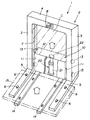
最初に、本発明の第1の実施の形態を図1により説明する。第1の実施の形態に係わる段差解消リフター1は、概略的には、移動可能で必要箇所に設置されるスタンド2と、このスタンド2に案内されて上下動する駆動体10と、この駆動体10の下端部から前方に延びている支持アーム14、14に取り付けられる乗り板15とからなっている。
First, a first embodiment of the present invention will be described with reference to FIG. A level difference elimination lifter 1 according to the first embodiment is schematically illustrated as a
スタンド2は、前後方向に所定の厚みを有する側枠3、3と、これらの側枠3、3の上端部を結合している天井枠4とから門型に構成されている。そして、側枠3、3の下端部から前方に一対の脚部5、5が延びている。これらの一対の脚部5、5は、本実施の形態では複数本の固定ボルト6、6、…により床等に固定されている状態で示されている。また、側枠3、3の内側には凹形を呈する案内溝7、7が互いに向き合って縦方向に形成され、天井枠4には、後述するピストンシリンダユニット20に圧力水を給排する操作レバー8が取り付けられている。
The
このように構成されているスタンド2内に、駆動機構として上下方向に駆動される駆動体10が設けられている。駆動体10は、両側板11、11と天板12とから、下方が開放された略箱状を呈するように構成され、その両側板11、11にスタンド2の側枠3、3の案内溝7、7内を転がるガイドローラ13、13、…が設けられている。駆動体10は、これらのガイドローラ13、13、…を介して、スタンド2の側枠3、3の案内溝7、7に案内されて上下動する。駆動体10の下方端から前方に向かって一対の支持アーム14、14が延びている。これらの支持アーム14、14に、乗り板15が取り付けられている。この乗り板15は、図1では2点鎖線で示され具体的な構造は示されていないが、手すり、車椅子の滑り止め等が適宜取り付けられている。
A
このような駆動体10内にピストンシリンダユニット20が設けられている。すなわち、図1に示されている実施の形態では、ピストンシリンダユニット20のシリンダ21が、床等に着座するように、そしてピストンロッド22の先端部が駆動体10の天板12を下から支持するように設けられている。また、駆動体10内には、図1には示されていないが、流量調整弁、切替バルブ等も設けられている。水道栓に接続されるホースは、これらの流量調整弁、切替バルブ等を介して、シリンダ21のピストンヘッド室あるいはピストンロッド室に接続される。そして、これらの流量調整弁、切替バルブは、機械的な例えばワイヤで操作レバー8に接続されている。したがって、操作レバー8によりピストンシリンダユニット20に供給する水道水の単位時間当たりの流量を調節することも、また水道水の供給方向も切り替えることができる。なお、スタンド2の内部は、透明な安全カバーCが覆われている。
A
次に、上記段差解消リフターの使用法について説明する。段差のある必要箇所へ移動させ、脚部5、5を固定ボルト6、6、…により固定する。また、水道栓と、流量調整弁および切替バルブを介してピストンシリンダユニット20とを接続する。このとき、可撓性のホースを利用すると、設置位置に融通性が得られる。これで設置が完了する。利用者は、乗り板15に乗り操作レバー8を操作する。そうすると、所定量に絞られた水道水がピストンシリンダユニット20に供給され、駆動体10がピストンロッド22により所定速度で上昇し、乗り板15も上昇する。所定高さまで上昇すると、自動停止する。あるいは操作レバー8を操作する。水道水の供給が止まり、乗り板15はロックされ所定位置に保持される。乗り板15から降りる。これにより、所定高さまで登ることができる。同様な操作をして、下方位置へ降りることができる。全く同様にして、荷物を運搬できることは明らかである。
Next, the usage method of the said level | step difference elimination lifter is demonstrated. It moves to the required location with a level | step difference, and fixes the
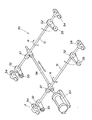
図2により、本発明の第2の実施の形態を説明する。第2の実施の形態によってもピストンシリンダユニット20が適用されるが、このピストンシリンダユニット20と乗り板との間に介在されている駆動機構30は、水平方向に配置されている2本の回転軸31、31と、これらの回転軸31,31に固定されている4個の、段差に相当する所定長さの揺動レバー32、32、…とから構成されている。さらに詳しくは、回転軸31、31は、所定間隔に配置され、軸受34、34、…により回転自在に軸受けされている。そして、これらの回転軸31、31に揺動レバー32、32、…の端部が固定されている。揺動レバー32、32、…の先端部には支持ローラ35、35、…が設けられ、これらの支持ローラ35、35、…に乗り板が支持されるようになっている。
A second embodiment of the present invention will be described with reference to FIG. The
ピストンシリンダユニット20のロッドには、回転軸31、31を横切るようにして駆動棒36が接続されている。そして、この駆動棒36と回転軸31、31は、接続具37、37により、駆動棒36が矢印Sで示されているように直線的に往復動するとき、回転軸31、31が矢印R、Rで示されているように揺動的に回転するように接続されている。第2の実施の形態によっても、乗り板、この乗り板を上下方向にガイドする枠体、流量調整弁、切替バルブ等も適宜設けられているが、図2には示されていない。上記したようなピストンシリンダユニット20、回転軸31、31、乗り板等はユニット化され、流量調整弁、切替バルブ等も搭載され、必要な箇所へ容易に移動できるようになっている。第2の実施の形態も第1の実施の形態と同様に作用することが明であるので、詳しい説明はしないが、ピストンシリンダユニット20に水道水を給排すると、回転軸31、31が揺動的に回転駆動され、揺動レバー32、32が揺動的に上下動する。したがって、揺動レバー32、32の先端部に設けられている支持ローラ35、35、…に支持されている乗り板も上下動する。これにより、段差間を移動できる。
A
本発明は、上記実施の形態に限定されることなく色々な形で実施できる。例えば、上記実施の形態では、主として室内に配置される例について説明したが、配管あるいは水ホースを引くだけで、屋外でも同様に設置できることは明らかである。また、駆動源には水道水を適用する旨説明したが、所定高さに設置されている雨水タンク、貯水タンク等の水も同様に利用できる。 The present invention is not limited to the above embodiment and can be implemented in various forms. For example, in the above-described embodiment, the example of being arranged mainly indoors has been described, but it is obvious that it can be similarly installed outdoors by simply pulling a pipe or a water hose. Moreover, although it demonstrated that tap water was applied to a drive source, the water of a rainwater tank, a storage tank, etc. installed in the predetermined height can be used similarly.
1 段差解消リフター 2 スタンド
5 脚部 10 駆動体(駆動機構)
14 支持アーム 15 乗り板
20 ピストンシリンダユニット 30 駆動機構
31 回転軸 32 揺動レバー 35 支持ローラ
DESCRIPTION OF SYMBOLS 1 Level | step-
14
Claims (3)
前記乗り板が、前記原動機により前記駆動機構を介して、第1の位置と、この第1の位置より所定量だけ高い第2の位置との間を上下方向に駆動さるようになっている段差解消リフターであって
前記原動機は、水圧で作動するピストンシリンダユニットから構成されていることを特徴とする段差解消リフター。 It consists of a riding board on which a person, a wheelchair, an article or the like rides, a prime mover that drives the riding board in a vertical direction, and a drive mechanism that is interposed between the riding board and the prime mover,
A step in which the ride board is driven in the vertical direction between the first position and a second position that is higher than the first position by a predetermined amount via the drive mechanism by the prime mover. It is a cancellation lifter, The said motor | power_engine is comprised from the piston cylinder unit act | operated by water pressure, The level | step difference cancellation lifter characterized by the above-mentioned.
Priority Applications (1)
| Application Number | Priority Date | Filing Date | Title |
|---|---|---|---|
| JP2004119769A JP2005296476A (en) | 2004-04-15 | 2004-04-15 | Leveling lifter |
Applications Claiming Priority (1)
| Application Number | Priority Date | Filing Date | Title |
|---|---|---|---|
| JP2004119769A JP2005296476A (en) | 2004-04-15 | 2004-04-15 | Leveling lifter |
Publications (1)
| Publication Number | Publication Date |
|---|---|
| JP2005296476A true JP2005296476A (en) | 2005-10-27 |
Family
ID=35328728
Family Applications (1)
| Application Number | Title | Priority Date | Filing Date |
|---|---|---|---|
| JP2004119769A Pending JP2005296476A (en) | 2004-04-15 | 2004-04-15 | Leveling lifter |
Country Status (1)
| Country | Link |
|---|---|
| JP (1) | JP2005296476A (en) |
Cited By (2)
| Publication number | Priority date | Publication date | Assignee | Title |
|---|---|---|---|---|
| JP2015229542A (en) * | 2014-06-04 | 2015-12-21 | 中西金属工業株式会社 | Step eliminating lifting device |
| CN107686073A (en) * | 2017-09-28 | 2018-02-13 | 南阳英良石业有限公司 | Hilllock platen press mould trolley |
Citations (8)
| Publication number | Priority date | Publication date | Assignee | Title |
|---|---|---|---|---|
| JPS4854660A (en) * | 1971-11-11 | 1973-08-01 | ||
| JPS602600A (en) * | 1983-06-21 | 1985-01-08 | 株式会社メイキコウ | Lifting gear for table |
| JPH01171552A (en) * | 1988-09-29 | 1989-07-06 | Shinyaesu Rihabiri Kk | Elevating mechanism in patient elevating device |
| JPH06103Y2 (en) * | 1988-09-08 | 1994-01-05 | 株式会社日本メディックス | Lifting mechanism of patient lifting device |
| JPH0748259Y2 (en) * | 1993-03-15 | 1995-11-08 | 株式会社ソーワエムデイセンター | lift device |
| JPH0833694A (en) * | 1994-07-26 | 1996-02-06 | Mikuni Corp | Lifting device for bathing care device |
| JPH10182084A (en) * | 1996-12-25 | 1998-07-07 | Meikikou:Kk | Electric lift equipment |
| JP2003026396A (en) * | 2001-07-13 | 2003-01-29 | Masazo Tamura | Assisting device for step of stairs |
-
2004
- 2004-04-15 JP JP2004119769A patent/JP2005296476A/en active Pending
Patent Citations (8)
| Publication number | Priority date | Publication date | Assignee | Title |
|---|---|---|---|---|
| JPS4854660A (en) * | 1971-11-11 | 1973-08-01 | ||
| JPS602600A (en) * | 1983-06-21 | 1985-01-08 | 株式会社メイキコウ | Lifting gear for table |
| JPH06103Y2 (en) * | 1988-09-08 | 1994-01-05 | 株式会社日本メディックス | Lifting mechanism of patient lifting device |
| JPH01171552A (en) * | 1988-09-29 | 1989-07-06 | Shinyaesu Rihabiri Kk | Elevating mechanism in patient elevating device |
| JPH0748259Y2 (en) * | 1993-03-15 | 1995-11-08 | 株式会社ソーワエムデイセンター | lift device |
| JPH0833694A (en) * | 1994-07-26 | 1996-02-06 | Mikuni Corp | Lifting device for bathing care device |
| JPH10182084A (en) * | 1996-12-25 | 1998-07-07 | Meikikou:Kk | Electric lift equipment |
| JP2003026396A (en) * | 2001-07-13 | 2003-01-29 | Masazo Tamura | Assisting device for step of stairs |
Cited By (2)
| Publication number | Priority date | Publication date | Assignee | Title |
|---|---|---|---|---|
| JP2015229542A (en) * | 2014-06-04 | 2015-12-21 | 中西金属工業株式会社 | Step eliminating lifting device |
| CN107686073A (en) * | 2017-09-28 | 2018-02-13 | 南阳英良石业有限公司 | Hilllock platen press mould trolley |
Similar Documents
| Publication | Publication Date | Title |
|---|---|---|
| US10653576B1 (en) | Apparatus for assisting toilet user in standing up | |
| CN104495573A (en) | Intelligent stair climbing walking replacing machine | |
| JP2009082568A (en) | Assistive chair for vehicle for the disabled | |
| JP2005296476A (en) | Leveling lifter | |
| JPH05118180A (en) | Semiautomatic door | |
| TWM477459U (en) | Stair lift | |
| CN204369364U (en) | Intelligence climbs the pedal closing-folding mechanism of building machine instead of walk | |
| JP7409587B1 (en) | Self-propelled handrail and method for manufacturing self-propelled handrail | |
| US20040139542A1 (en) | Bathing assist device | |
| JP2007022751A (en) | Moving device for seating means in elevator communication stairs | |
| KR20020063482A (en) | Hair washing apparatus | |
| JP4689102B2 (en) | Stair lift | |
| JP2001057919A (en) | Elevatable chair | |
| CN212292430U (en) | A flat step stair device | |
| JP4972757B2 (en) | Monorail stair lift | |
| JP3450832B2 (en) | Stair climbing device | |
| US6098215A (en) | Toilet seat lifting device | |
| KR20140094279A (en) | Patients Lifting Device For Toilet | |
| JP2003339473A (en) | Storage chair | |
| CN207713218U (en) | Ceiling mounting type passageway lift chair mechanism and ceiling mounting type passageway lift | |
| CN219326476U (en) | Platform elevator car | |
| JP2003159281A (en) | Transfer device | |
| JP2001206660A (en) | One-man chair type home elevator | |
| JP3035006U (en) | Lifter for people with disabilities | |
| JP2005119765A (en) | Wheelchair leveling machine |
Legal Events
| Date | Code | Title | Description |
|---|---|---|---|
| A711 | Notification of change in applicant |
Free format text: JAPANESE INTERMEDIATE CODE: A711 Effective date: 20051124 |
|
| RD02 | Notification of acceptance of power of attorney |
Free format text: JAPANESE INTERMEDIATE CODE: A7422 Effective date: 20060106 |
|
| A621 | Written request for application examination |
Effective date: 20070222 Free format text: JAPANESE INTERMEDIATE CODE: A621 |
|
| A521 | Written amendment |
Free format text: JAPANESE INTERMEDIATE CODE: A821 Effective date: 20070518 |
|
| RD02 | Notification of acceptance of power of attorney |
Free format text: JAPANESE INTERMEDIATE CODE: A7422 Effective date: 20070518 |
|
| A131 | Notification of reasons for refusal |
Free format text: JAPANESE INTERMEDIATE CODE: A131 Effective date: 20100112 |
|
| A521 | Written amendment |
Effective date: 20100312 Free format text: JAPANESE INTERMEDIATE CODE: A523 |
|
| A131 | Notification of reasons for refusal |
Free format text: JAPANESE INTERMEDIATE CODE: A131 Effective date: 20100518 |
|
| A521 | Written amendment |
Effective date: 20100720 Free format text: JAPANESE INTERMEDIATE CODE: A523 |
|
| A02 | Decision of refusal |
Free format text: JAPANESE INTERMEDIATE CODE: A02 Effective date: 20110104 |