JP2005296461A - Magnetic resonance imaging equipment - Google Patents
Magnetic resonance imaging equipment Download PDFInfo
- Publication number
- JP2005296461A JP2005296461A JP2004119439A JP2004119439A JP2005296461A JP 2005296461 A JP2005296461 A JP 2005296461A JP 2004119439 A JP2004119439 A JP 2004119439A JP 2004119439 A JP2004119439 A JP 2004119439A JP 2005296461 A JP2005296461 A JP 2005296461A
- Authority
- JP
- Japan
- Prior art keywords
- magnetic field
- coil
- magnetic resonance
- resonance imaging
- gradient magnetic
- Prior art date
- Legal status (The legal status is an assumption and is not a legal conclusion. Google has not performed a legal analysis and makes no representation as to the accuracy of the status listed.)
- Withdrawn
Links
Images

Landscapes
- Magnetic Resonance Imaging Apparatus (AREA)
Abstract
【課題】S/N比の低下を抑制しつつより短時間で画像データを収集することが可能な磁気共鳴イメージング装置である。
【解決手段】磁気共鳴イメージング装置20は、感度分布がそれぞれ異なる複数の高周波コイル24を用いてパラレルイメージングを行う磁気共鳴イメージング装置20であって、異なる位相の高周波磁場パルスを略同時に被検体Pに印加することにより複数の断面を選択励起する手段と、複数の高周波コイル24それぞれにより被検体Pから発生する磁気共鳴信号を収集する手段と、高周波コイル24それぞれにより得られた前記磁気共鳴信号により画像を生成した後、前記感度分布に基づきパラレルイメージングの展開処理を行う手段41とを備える。
【選択図】 図1A magnetic resonance imaging apparatus capable of collecting image data in a shorter time while suppressing a decrease in S / N ratio.
A magnetic resonance imaging apparatus 20 is a magnetic resonance imaging apparatus 20 that performs parallel imaging using a plurality of high-frequency coils 24 having different sensitivity distributions, and simultaneously applies high-frequency magnetic field pulses of different phases to a subject P. A means for selectively exciting a plurality of cross-sections by application, a means for collecting magnetic resonance signals generated from the subject P by each of the plurality of high-frequency coils 24, and an image by the magnetic resonance signals obtained by each of the high-frequency coils 24 Is generated, and parallel image development processing is performed based on the sensitivity distribution.
[Selection] Figure 1
Description
本発明は、核磁気共鳴信号を利用して被検体の画像を撮像する磁気共鳴イメージング装置に係り、特に複数のコイルを用いて画像を撮像する磁気共鳴イメージング装置に関する。 The present invention relates to a magnetic resonance imaging apparatus that captures an image of a subject using a nuclear magnetic resonance signal, and more particularly to a magnetic resonance imaging apparatus that captures an image using a plurality of coils.
従来、医療現場におけるモニタリング装置として、図8に示すような磁気共鳴イメージング(MRI:Magnetic Resonance Imaging)装置1が利用される(例えば特許文献1参照)。
Conventionally, a magnetic resonance imaging (MRI)
磁気共鳴イメージング装置1は、静磁場を形成する筒状の静磁場用磁石2内部にセットされた被検体Pの撮像領域に傾斜磁場コイルユニット3の各傾斜磁場コイル3x、3y、3zでX軸、Y軸、Z軸方向の傾斜磁場を形成するとともにRF(Radio Frequency)コイル4からラーモア周波数の高周波(RF)信号を送信することにより被検体P内の原子核スピンを磁気的に共鳴させ、励起により生じた核磁気共鳴(NMR:Nuclear Magnetic Resonance)信号を利用して被検体Pの画像を再構成する装置である。
The magnetic
すなわち、予め静磁場電源5により静磁場用磁石2内部に静磁場が形成される。さらに、入力装置6からの指令によりシーケンスコントローラ制御手段7は、信号の制御情報であるシーケンスをシーケンスコントローラ8に与え、シーケンスコントローラ8はシーケンスに従って各傾斜磁場コイル3x、3y、3zに接続された傾斜磁場電源9およびRFコイル4に高周波信号を与える送信器10を制御する。このため、撮像領域に傾斜磁場が形成され、被検体Pには高周波信号が送信される。
That is, a static magnetic field is previously formed in the static
この際、傾斜磁場コイル3x、3y、3zにより形成されたX軸傾斜磁場、Y軸傾斜磁場,Z軸傾斜磁場は主として、位相エンコード(PE:phase encoding)用傾斜磁場、読出し(RO:readout)用傾斜磁場、スライスエンコード(SE:slice encoding)用傾斜磁場としてそれぞれ使用される。このため、原子核の位置情報であるX座標、Y座標、Z座標はそれぞれ原子核スピンの位相、周波数、スライスの位置に変換され、位相エンコード量を変えながらシーケンスが繰返し実行される。
At this time, the X-axis gradient magnetic field, the Y-axis gradient magnetic field, and the Z-axis gradient magnetic field formed by the gradient
そして、被検体P内の原子核スピンの励起に伴って発生したNMR信号は、RFコイル4で受信されるとともに受信器11に与えられてデジタル化された生データ(raw data)に変換される。さらに、生データは、シーケンスコントローラ8を介してシーケンスコントローラ制御手段7に取り込まれ、シーケンスコントローラ制御手段7は生データデータベース12に形成されたK空間(フーリエ空間)に生データを配置する。そして、画像再構成手段13が、K空間に配置された生データに対してフーリエ変換を実行することにより、被検体Pの再構成画像が得られ、画像表示手段14により再構成画像が適宜表示装置15に与えられて表示される。
Then, the NMR signal generated along with the excitation of the nuclear spin in the subject P is received by the
このような磁気共鳴イメージング装置1による撮影技術として、複数の断面を異なる位相で同時に順次選択励起することにより、1回の励起で通常の撮影に比べて複数倍、例えば図9に示すようにPE方向に4倍の断面画像を撮影する技術が提案される。この技術により2倍または4倍の数の断面画像を撮影する場合、1.4倍または2倍のS/N比が得られるという利点がある。
As an imaging technique using such a magnetic
一方、RFコイル4を複数の表面コイルを備えたマルチコイルで構成し、各表面コイルで同時にNMR信号を受信してより多くの生データを短時間で収集することにより、撮像時間を短縮するパラレルイメージング技術が提案される(例えば非特許文献1、非特許文献2、非特許文献3、非特許文献4参照)。
On the other hand, the
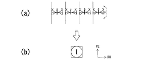
この撮影方法では、図10(a)に示すように、例えば4つの各表面コイルにより同一断面の画像がそれぞれ撮影される。この際、各画像には、折り返し部分が生じる。そこで、表面コイルの感度分布に基づいて展開(アンフォールディング)処理により、折り返し部分が所定の位置にマッピングされて図10(b)に示すような折り返し部分のない画像が得られる。
従来の複数の断面を異なる位相で同時に順次選択励起する撮像方法を用いた磁気共鳴イメージング装置1では、2倍ないし4倍数の断面におけるデータを得るために、実際には2倍ないし4倍の撮像時間を必要とする。このため、S/N比を向上することができるにも拘わらず、十分に活用することができず、殆ど試用されていないのが現状である。
In the magnetic
一方、RFコイル4を複数の表面コイルを備えたマルチコイルで構成した磁気共鳴イメージング装置1では、通常の撮像方法による撮影と比較して撮像時間が短くなるもののS/N比が低下するという問題がある。例えば、撮影時間が1/2または1/4となった場合には、S/N比は1/1.4または1/2となる。
On the other hand, in the magnetic
本発明はかかる従来の事情に対処するためになされたものであり、S/N比の低下を抑制しつつより短時間で画像データを収集することが可能な磁気共鳴イメージング装置を提供することを目的とする。 The present invention has been made to cope with such a conventional situation, and provides a magnetic resonance imaging apparatus capable of collecting image data in a shorter time while suppressing a decrease in the S / N ratio. Objective.
本発明に係る磁気共鳴イメージング装置は、上述の目的を達成するために、請求項1に記載したように、感度分布がそれぞれ異なる複数の高周波コイルを用いてパラレルイメージングを行う磁気共鳴イメージング装置であって、異なる位相の高周波磁場パルスを略同時に被検体に印加することにより複数の断面を選択励起する手段と、前記複数の高周波コイルそれぞれにより前記被検体から発生する磁気共鳴信号を収集する手段と、前記高周波コイルそれぞれにより得られた前記磁気共鳴信号により画像を生成した後、前記感度分布に基づきパラレルイメージングの展開処理を行う手段とを備えることを特徴とするものである。 In order to achieve the above object, a magnetic resonance imaging apparatus according to the present invention is a magnetic resonance imaging apparatus that performs parallel imaging using a plurality of high-frequency coils having different sensitivity distributions. Means for selectively exciting a plurality of cross sections by applying high-frequency magnetic field pulses of different phases to the subject substantially simultaneously, means for collecting magnetic resonance signals generated from the subject by the plurality of high-frequency coils, and Means for performing parallel imaging development processing based on the sensitivity distribution after an image is generated by the magnetic resonance signal obtained by each of the high-frequency coils.
本発明に係る磁気共鳴イメージング装置においては、S/N比の低下を抑制しつつより短時間で画像データを収集することができる。 In the magnetic resonance imaging apparatus according to the present invention, image data can be collected in a shorter time while suppressing a decrease in the S / N ratio.
本発明に係る磁気共鳴イメージング装置の実施の形態について添付図面を参照して説明する。 Embodiments of a magnetic resonance imaging apparatus according to the present invention will be described with reference to the accompanying drawings.
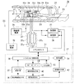
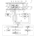
図1は本発明に係る磁気共鳴イメージング装置の実施の形態を示す機能ブロック図である。 FIG. 1 is a functional block diagram showing an embodiment of a magnetic resonance imaging apparatus according to the present invention.
磁気共鳴イメージング装置20は、静磁場を形成する筒状の静磁場用磁石21と、この静磁場用磁石21の内部に設けられたシムコイル22、傾斜磁場コイルユニット23およびRF(高周波)コイル24とを図示しないガントリに内蔵した構成である。
The magnetic
また、磁気共鳴イメージング装置20には、制御系25が備えられる。制御系25は、静磁場電源26、傾斜磁場電源27、シムコイル電源28、送信器29、受信器30、シーケンスコントローラ31およびコンピュータ32を具備している。制御系25の傾斜磁場電源27は、X軸傾斜磁場電源27x、Y軸傾斜磁場電源27yおよびZ軸傾斜磁場電源27zで構成される。また、コンピュータ32は、図示しない演算装置および記憶装置を備え、入力装置33および表示装置34が設けられる。
In addition, the magnetic
静磁場用磁石21は静磁場電源26と接続され、静磁場電源26から供給された電流により撮像領域に静磁場を形成させる機能を有する。また、静磁場用磁石21の内側には、同軸上に筒状のシムコイル22が設けられる。シムコイル22はシムコイル電源28と接続され、シムコイル電源28からシムコイル22に電流が供給されて静磁場が均一化されるように構成される。
The static
傾斜磁場コイルユニット23は、X軸傾斜磁場コイル23x、Y軸傾斜磁場コイル23yおよびZ軸傾斜磁場コイル23zで構成され、静磁場用磁石21の内部において筒状に形成される。傾斜磁場コイルユニット23の内側には寝台35が設けられて撮像領域とされ、寝台35には被検体Pがセットされる。RFコイル24はガントリに内蔵されず、寝台35や被検体P近傍に設けられる場合もある。
The gradient magnetic
また、傾斜磁場コイルユニット23は、傾斜磁場電源27と接続される。傾斜磁場コイルユニット23のX軸傾斜磁場コイル23x、Y軸傾斜磁場コイル23yおよびZ軸傾斜磁場コイル23zはそれぞれ、傾斜磁場電源27のX軸傾斜磁場電源27x、Y軸傾斜磁場電源27yおよびZ軸傾斜磁場電源27zと接続される。
The gradient magnetic
そして、X軸傾斜磁場電源27x、Y軸傾斜磁場電源27yおよびZ軸傾斜磁場電源27zからそれぞれX軸傾斜磁場コイル23x、Y軸傾斜磁場コイル23yおよびZ軸傾斜磁場コイル23zに供給された電流により、撮像領域にそれぞれX軸方向の傾斜磁場Gx、Y軸方向の傾斜磁場Gy、Z軸方向の傾斜磁場Gzを形成することができるように構成される。
The X-axis gradient magnetic
RFコイル24はマルチコイルで構成され、送信器29および受信器30と接続される。RFコイル24は、送信器29から高周波信号を受けて被検体Pに高周波磁場パルスを送信する機能と、被検体P内部の原子核スピンの高周波信号による励起に伴って発生したNMR信号を受信して受信器30に与える機能を有する。
The
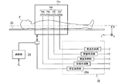
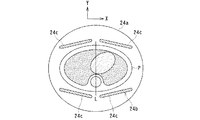
図2は図1に示すRFコイル24の詳細構成の一例を示す図であり、図3は図2に示すWBコイル24aとフェーズドアレイコイル24bの配置例を示す断面模式図である。
2 is a diagram showing an example of a detailed configuration of the
RFコイル24は、例えば送信用のRFコイル24と受信用のRFコイル24とから構成される。送信用のRFコイル24には、全身用(WB:whole-body)コイル24aが用いられる一方、受信用のRFコイル24には、複数のコイルを具備するフェーズドアレイコイル24bが用いられる。フェーズドアレイコイル24bは、複数の表面コイル24cを備え、各表面コイル24cは、それぞれ個別に受信系回路30aと接続される。
The
また、フェーズドアレイコイル24bの各表面コイル24cは、例えば被検体Pの特定関心部位を含む断面Lの周囲となるZ軸周りに対称に配置される。さらにフェーズドアレイコイル24bの外側には、WBコイル24aが設けられる。そして、WBコイル24aにより被検体Pに高周波信号を送信する一方、WBコイル24aまたはフェーズドアレイコイル24bの各表面コイル24cにより多チャンネルで特定関心部位を含む断面LからのNMR信号を受信して各受信器30の各受信系回路30aに与えることができるように構成される。
In addition, the
一方、制御系25のシーケンスコントローラ31は、傾斜磁場電源27、送信器29および受信器30と接続される。シーケンスコントローラ31は傾斜磁場電源27、送信器29および受信器30を駆動させるために必要な制御情報、例えば傾斜磁場電源27に印加すべきパルス電流の強度や印加時間、印加タイミング等の動作制御情報を記述したシーケンス情報を記憶する機能と、記憶した所定のシーケンスに従って傾斜磁場電源27、送信器29および受信器30を駆動させることによりX軸傾斜磁場Gx、Y軸傾斜磁場Gy,Z軸傾斜磁場Gzおよび高周波信号を発生させる機能を有する。
On the other hand, the
また、シーケンスコントローラ31は、受信器30からデジタル化されたNMR信号である生データ(raw data)を受けてコンピュータ32に与えるように構成される。
In addition, the
このため、送信器29には、シーケンスコントローラ31から受けた制御情報に基づいて高周波信号をRFコイル24に与える機能が備えられる一方、受信器30には、RFコイル24から受けたNMR信号に所要の信号処理を実行するとともにA/D変換することにより、デジタル化されたNMR信号である生データを生成する機能と、生成した生データをシーケンスコントローラ31に与える機能とが備えられる。
For this reason, the
また、コンピュータ32には、プログラムが読み込まれて実行されることにより励起断面設定手段36、パルスシーケンス生成手段37、シーケンスコントローラ制御手段38、生データデータベース39、画像再構成手段40、展開処理手段41および画像表示手段42として機能する。ただし、プログラムによらず、特定の回路を設けてコンピュータ32を構成してもよい。
Further, the
励起断面設定手段36は、Quad法によるスキャンを実行する際に励起させるスライス、すなわちスライス方向の位相をマルチコイルの各コイルの感度分布に応じて設定する機能と、設定したスライス方向の位相をパルスシーケンス生成手段37に与える機能とを有する。尚、Quad法の詳細については、特開平10−277005号公報に記載されている。 The excitation cross-section setting means 36 functions to set the slice to be excited when executing the scan by the quad method, that is, the function of setting the phase in the slice direction according to the sensitivity distribution of each coil of the multi-coil, and the phase in the set slice direction A function to be given to the sequence generation means 37. The details of the quad method are described in JP-A-10-277005.
パルスシーケンス生成手段37は、Quad法によるスキャンをマルチコイルの各コイルにより実行するためのパルスシーケンスであるQuadScanシーケンスを生成する機能と、生成したQuadScanシーケンスをシーケンスコントローラ制御手段38に与える機能とを有する。この際、QuadScanシーケンスによるスキャン実行時に励起させるスライスが、励起断面設定手段36により設定されたスライスとなるようにされる。
The pulse
シーケンスコントローラ制御手段38は、入力装置33またはその他の構成要素からの情報に基づいて、パルスシーケンス生成手段37から受けたQuadScanシーケンスをシーケンスコントローラ31に与えることによりスキャンを実行させる機能を有する。また、シーケンスコントローラ制御手段38は、シーケンスコントローラ31からQuadScanシーケンスによるスキャン実行によりマルチコイルのコイル毎に収集された生データを受けて生データデータベース39に形成されたK空間(フーリエ空間)に配置する機能を有する。
The sequence
このため、生データデータベース39には、受信器30において生成されたコイル毎の各生データが保存される。すなわち、生データデータベース39に形成されたK空間に生データが配置される。
For this reason, each raw data for each coil generated in the
画像再構成手段40は、生データデータベース39のK空間に配置された生データに対してフーリエ変換(FT)を実行することにより被検体Pの画像データをパラレルイメージング技術を用いて再構成させる機能と、再構成させた画像データを展開処理手段41に与える機能とを有する。
The image reconstruction means 40 has a function of reconstructing image data of the subject P using parallel imaging technology by performing Fourier transform (FT) on the raw data arranged in the K space of the
展開処理手段41は、画像再構成手段40から受けた画像データに対してRFコイル24の感度分布に基づいてパラレルイメージングの展開(アンフォールディング)処理を実行する機能を有する。
The
次に磁気共鳴イメージング装置20の作用について説明する。
Next, the operation of the magnetic
図4は、図1に示す磁気共鳴イメージング装置20により被検体Pの断層画像を撮像する際の手順を示すフローチャートであり、図中Sに数字を付した符号はフローチャートの各ステップを示す。
FIG. 4 is a flowchart showing a procedure when a tomographic image of the subject P is picked up by the magnetic
まずステップS1において、Quad法によるスキャンを実行する際に励起させる断面(スライス)、すなわちスライス方向の位相が励起断面設定手段36により設定される。
First, in
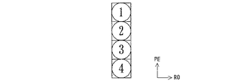
図5は、図1に示す磁気共鳴イメージング装置20により設定される励起断面および励起順序の一例を示す図である。
FIG. 5 is a diagram showing an example of the excitation cross section and the excitation order set by the magnetic
1回に励起させる断面の個数および位置は任意に設定することができる。例えば、図5(a)に示すように、被検体Pの頭部断面をスキャンする場合に、隣接する4つの断面を1回で励起させることができる。 The number and position of the cross sections excited at one time can be arbitrarily set. For example, as shown in FIG. 5A, when scanning a cross section of the head of the subject P, four adjacent cross sections can be excited at one time.
一方、後述するマルチコイルでパラレルイメージングによるスキャンを実行して得られる画像には、折り返しが発生するが、この折り返しを展開する処理は、各表面コイル24cの感度が互いに異なる程、正確に実施することができる。そこで、折り返し画像の展開処理をより正確に実施するために、マルチコイルの各表面コイル24cのパラレルイメージングにとっての感度分布が適切となるように同時に励起させる断面の位相を設定することができる。
On the other hand, aliasing occurs in an image obtained by executing scanning by parallel imaging using a multi-coil described later. The process of developing this aliasing is more accurately performed as the sensitivity of each
例えば図5(b)に示すように1回で励起させる断面を互いに隣接させずに、一定の間隔で4つの断面を設定することができる。このように励起断面を設定すれば、各断面間において表面コイル24cの感度の相違を励起断面を隣接させる場合に比べて大きく設定できる。そして、より正確に後の展開処理を実施することができる。
For example, as shown in FIG. 5B, four cross sections can be set at regular intervals without causing the cross sections excited at one time to be adjacent to each other. If the excitation cross section is set in this way, the difference in sensitivity of the
次に、ステップS2において、パルスシーケンス生成手段37により、QuadScanシーケンスが生成されてシーケンスコントローラ制御手段38に与えられる。
Next, in step S <b> 2, a QuadScan sequence is generated by the pulse
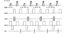
図6は、図1に示す磁気共鳴イメージング装置20により生成されるQuadScanシーケンスの一例を示す図である。
FIG. 6 is a diagram showing an example of a QuadScan sequence generated by the magnetic
図6に示すようにQuadScanシーケンスでは、1回で励起させる断面の数に応じて、RFパルスに複数の励起パルスが若干タイミングをずらして設けられる。このとき各励起パルスの位相が一定量ずつ変化するように設定される。図6は、同時に4つの断面を励起させる場合におけるQuadScanシーケンスの例である。従って、RFパルスは、位相が一定量ずつ変化する4つの励起パルスを有する。 As shown in FIG. 6, in the QuadScan sequence, a plurality of excitation pulses are provided in the RF pulse with slightly different timings according to the number of cross sections excited at one time. At this time, the phase of each excitation pulse is set to change by a certain amount. FIG. 6 is an example of a QuadScan sequence in the case where four cross sections are excited simultaneously. Therefore, the RF pulse has four excitation pulses whose phase changes by a certain amount.
またX、Y、Z軸方向に印加される各傾斜磁場およびアナログ−デジタル変換回路(ADC:analog to digital converter)の動作タイミングがQuadScanシーケンスにより設定される。図6の例は、SE(スピンエコー)法によるシーケンスの例であるが、他のシーケンスであってもよい。この際、Y軸方向のPE用の傾斜磁場GRADYの刻みは撮影視野を広くするために、例えば通常の1/4とされる。 The gradient magnetic fields applied in the X, Y, and Z axis directions and the operation timing of an analog-to-digital converter (ADC) are set by a QuadScan sequence. The example of FIG. 6 is an example of a sequence by the SE (spin echo) method, but may be another sequence. At this time, the increment of the gradient magnetic field GRADY for PE in the Y-axis direction is set to, for example, a normal 1/4 in order to widen the field of view.
次に、ステップS3において、被検体Pの生データが収集されて生データデータベース12に形成されたK空間に配置される。
Next, in step S <b> 3, raw data of the subject P is collected and placed in the K space formed in the
すなわち予め寝台35には被検体Pがセットされ、静磁場電源26から静磁場用磁石21に電流が供給されて撮像領域に静磁場が形成される。また、シムコイル電源28からシムコイル22に電流が供給されて撮像領域に形成された静磁場が均一化される。
In other words, the subject P is set in advance on the
次に、入力装置33からシーケンスコントローラ制御手段38に動作指令が与えられる。このため、シーケンスコントローラ制御手段38はQuadScanシーケンスをシーケンスコントローラ31に与える。シーケンスコントローラ31は、シーケンスコントローラ制御手段38から受けたQuadScanシーケンスに従って傾斜磁場電源27、送信器29および受信器30を駆動させることにより被検体Pがセットされた撮像領域にX軸傾斜磁場Gx、Y軸傾斜磁場Gy,Z軸傾斜磁場Gzを形成させるとともに、高周波信号を発生させる。
Next, an operation command is given from the
この際、傾斜磁場コイルにより形成されたX軸傾斜磁場Gx、Y軸傾斜磁場Gy,Z軸傾斜磁場Gzは主として、位相エンコード(PE)用傾斜磁場、読出し(RO)用傾斜磁場、スライスエンコード(SE)用傾斜磁場としてそれぞれ使用される。このため、被検体P内部における原子核のスピンの回転方向に規則性が現れ、SE用傾斜磁場によりZ軸方向に形成されたスライスにおける二次元的な位置情報であるX座標およびY座標は、PE用傾斜磁場およびRO用傾斜磁場によりそれぞれ被検体P内部における原子核のスピンの位相変化量および周波数変化量に変換される。 At this time, the X-axis gradient magnetic field Gx, the Y-axis gradient magnetic field Gy, and the Z-axis gradient magnetic field Gz formed by the gradient coil are mainly a phase encode (PE) gradient magnetic field, a read (RO) gradient magnetic field, and a slice encode ( Used as a gradient magnetic field for SE). For this reason, regularity appears in the spin rotation direction of the nuclei inside the subject P, and the X and Y coordinates, which are two-dimensional position information in the slice formed in the Z-axis direction by the SE gradient magnetic field, are PE The phase change amount and the frequency change amount of the spin of the nucleus inside the subject P are respectively converted by the gradient magnetic field for RO and the gradient magnetic field for RO.
そして、送信器29からQuadScanシーケンスに応じてRFコイル24の各チャンネルを経由して各WBコイル24aにそれぞれに高周波信号が与えられ、各WBコイル24aから被検体Pに異なる位相の高周波信号(高周波磁場パルス)が略同時に印加される。この際、高周波信号は複数の励起パルスで構成されるため、同時に複数のスライスが選択励起される。そして、被検体Pの内部において高周波信号の周波数に応じた各スライスに含まれる原子核の核磁気共鳴により生じたNMR信号が、RFコイル24の各表面コイル24cによりそれぞれ受信されて受信器30に与えられる。
A high frequency signal is given to each
受信器30は、RFコイル24の各表面コイル24cからNMR信号を受けて、前置増幅、中間周波変換、位相検波、低周波増幅、フィルタリング等の各種信号処理を実行する。さらに受信器30は、NMR信号をA/D変換することにより、デジタルデータのNMR信号である生データを生成する。受信器30は、生成した生データをシーケンスコントローラ31に与える。
The
シーケンスコントローラ31は、受信器30から受けた生データをシーケンスコントローラ制御手段38に与え、シーケンスコントローラ制御手段38は生データデータベース39に形成されたK空間に生データを配置する。
The
次に、ステップS4において、画像再構成手段40は、生データデータベース39のK空間に配置された生データに対してフーリエ変換(FT)を実行することにより被検体Pの画像データをパラレルイメージング技術により再構成させる。また必要な再構成処理が画像再構成手段40により実施される。そして、画像再構成手段40は、再構成させた画像データを展開処理手段41に与える。
Next, in step S4, the
次に、ステップS5において、展開処理手段41は、画像再構成手段40から受けた画像データに対して展開処理を実行する。
Next, in step S <b> 5, the
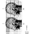
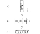
図7は、図1に示す磁気共鳴イメージング装置20による展開処理の方法を説明する図である。
FIG. 7 is a diagram for explaining a development processing method by the magnetic
尚、ここでは4つの断面1、2、3、4を同時に励起させた場合の例について説明する。
Here, an example in which four
パラレルイメージングにより得られた展開処理前の画像データは、複数の表面コイル24cを用いて得られるため、図7(a)に示すように、例えば4つの断面1、2、3,4が互いに重なった状態でPE方向に連続的に生成される。このため、通常の撮影で4つの断面の画像を得る場合に比べて短時間で画像データを再構成させることができる。
Since the image data before development processing obtained by parallel imaging is obtained by using a plurality of
そこで、図7(b)に示すように4つの断面1、2、3,4の中央部分ごとに分割することができる。分割した各断面1、2,3、4の画像には折り返し部分が存在する。従ってパラレルイメージングにより生じた折り返し部分の展開処理が必要となる。
Therefore, as shown in FIG. 7B, the four
ここで、従来のマルチコイルを用いて得られる画像の折り返し部分は、図10(a)に示すように単一の断面において生じるものであるのに対し、図7(b)に示す折り返し部分は、ある断面の一部が他の断面に折り返し部分として入り込んでいる。このため、従来の展開処理をそのまま施しても折り返し部分のない画像を得ることができない。 Here, the folded portion of the image obtained using the conventional multi-coil occurs in a single cross section as shown in FIG. 10A, whereas the folded portion shown in FIG. A part of a certain cross section enters the other cross section as a folded portion. For this reason, even if the conventional expansion process is performed as it is, an image without a folded portion cannot be obtained.
そこで、展開処理手段41は、単一の断面ではなく対応する他の断面に入り込んだ折り返し部分に対して展開処理を実施する。例えば、断面1の上部に入り込んだ断面4の下部および断面3の下部に入り込んだ断面4の上部をそれぞれ断面4にマッピングすることにより折り返しのない断面4を生成することができる。
Therefore, the unfolding processing means 41 performs unfolding processing on a folded portion that has entered a corresponding other section instead of a single section. For example, an unfolded
尚、図7は、隣接する断面に折り返し部分が入り込んだ例を示すが、励起パルスの位相を調節して励起断面の位置を変更するが可能であるため、折り返し部分の位置は必ずしも一定でなく、撮影条件に応じた折り返し画像が生成される。 Although FIG. 7 shows an example in which a folded portion enters an adjacent cross section, the position of the folded portion is not necessarily constant because the position of the excitation cross section can be changed by adjusting the phase of the excitation pulse. A folded image corresponding to the shooting conditions is generated.
従って、撮影条件に応じた適切な展開処理が展開処理手段41により実施される。
Accordingly, the
そして、このような展開処理により図7(c)のような折り返しのない各断面1、2、3、4の画像を得ることができる。さらに、得られた画像は適宜画像表示手段42により表示装置34に与えられて表示される。
And by such a development | deployment process, the image of each
以上の磁気共鳴イメージング装置20によれば、S/N比の低下を抑制しつつより短時間で画像データを収集することができる。
According to the magnetic
例えば、磁気共鳴イメージング装置20によれば、従来の技術と同等の精度で、従来のquad法によるスキャンと比較して撮影時間を1/2または1/4とし、かつ従来のマルチコイルを用いたスキャンと比較して、S/N比を1.4倍または2倍にすることができる。
For example, according to the magnetic
このため、磁気共鳴イメージング装置20によれば、被検体Pである患者のスループットの向上や診断能の向上を期待することができる。
For this reason, according to the magnetic
20 磁気共鳴イメージング装置
21 静磁場用磁石
23 傾斜磁場コイルユニット
24 RFコイル
24a WBコイル
24b フェーズドアレイコイル
24c 表面コイル
26 静磁場電源
27 傾斜磁場電源
29 送信器
30 受信器
31 シーケンスコントローラ
33 入力装置
34 表示装置
36 励起断面設定手段
37 パルスシーケンス生成手段
38 シーケンスコントローラ制御手段
39 生データデータベース
40 画像再構成手段
41 展開処理手段
42 画像表示手段
P 被検体
20 Magnetic
Claims (2)
Priority Applications (1)
| Application Number | Priority Date | Filing Date | Title |
|---|---|---|---|
| JP2004119439A JP2005296461A (en) | 2004-04-14 | 2004-04-14 | Magnetic resonance imaging equipment |
Applications Claiming Priority (1)
| Application Number | Priority Date | Filing Date | Title |
|---|---|---|---|
| JP2004119439A JP2005296461A (en) | 2004-04-14 | 2004-04-14 | Magnetic resonance imaging equipment |
Publications (1)
| Publication Number | Publication Date |
|---|---|
| JP2005296461A true JP2005296461A (en) | 2005-10-27 |
Family
ID=35328714
Family Applications (1)
| Application Number | Title | Priority Date | Filing Date |
|---|---|---|---|
| JP2004119439A Withdrawn JP2005296461A (en) | 2004-04-14 | 2004-04-14 | Magnetic resonance imaging equipment |
Country Status (1)
| Country | Link |
|---|---|
| JP (1) | JP2005296461A (en) |
Cited By (2)
| Publication number | Priority date | Publication date | Assignee | Title |
|---|---|---|---|---|
| JP2009082178A (en) * | 2007-09-27 | 2009-04-23 | Hitachi Ltd | Magnetic resonance equipment |
| CN103874457A (en) * | 2011-09-29 | 2014-06-18 | 株式会社日立医疗器械 | Magnetic resonance imaging equipment, high frequency magnetic field irradiation method and program |
-
2004
- 2004-04-14 JP JP2004119439A patent/JP2005296461A/en not_active Withdrawn
Cited By (3)
| Publication number | Priority date | Publication date | Assignee | Title |
|---|---|---|---|---|
| JP2009082178A (en) * | 2007-09-27 | 2009-04-23 | Hitachi Ltd | Magnetic resonance equipment |
| CN103874457A (en) * | 2011-09-29 | 2014-06-18 | 株式会社日立医疗器械 | Magnetic resonance imaging equipment, high frequency magnetic field irradiation method and program |
| CN103874457B (en) * | 2011-09-29 | 2016-02-03 | 株式会社日立医疗器械 | Magnetic resonance imaging apparatus and high frequency magnetic field illuminating method |
Similar Documents
| Publication | Publication Date | Title |
|---|---|---|
| CN100563555C (en) | Magnetic resonance imaging device and RF receiving coil device for magnetic resonance imaging | |
| JP4152381B2 (en) | Magnetic resonance imaging system | |
| JP4434753B2 (en) | Magnetic resonance imaging apparatus and magnetic resonance imaging collection data processing method | |
| EP2992351B1 (en) | Dixon-type water/fat separation mri using high-snr in-phase image and lower-snr at least partially out-of-phase image | |
| EP2411829B1 (en) | Mr imaging using parallel signal acquisition | |
| CN100482156C (en) | Method and system for accelerated imaging using parallel MRI | |
| CN102762997B (en) | RF antenna arrangement and method for multi-core MR image reconstruction involving parallel MRI | |
| CN102597795B (en) | MR imaging using navigators | |
| JP2014508622A (en) | MR image reconstruction using regularization constrained by prior information | |
| JP4381378B2 (en) | Magnetic resonance imaging system | |
| US20120046539A1 (en) | Dual-contrast mr imaging using fluid-attenuation inversion recovery (flair) | |
| EP1216421B1 (en) | Mr imaging apparatus for parallel multi-channel detection | |
| US20030144587A1 (en) | Customized spatial saturation pulse sequence for suppression of artifacts in MR images | |
| JP2006507071A (en) | Magnetic resonance method | |
| JP2002248089A (en) | Apparatus and method for magnetic resonance imaging | |
| JP4862073B2 (en) | Magnetic resonance imaging apparatus and magnetic resonance imaging collection data processing method | |
| JP2005296461A (en) | Magnetic resonance imaging equipment | |
| US20060132133A1 (en) | Method and system for spatial-spectral excitation by parallel RF transmission | |
| JP5142484B2 (en) | Magnetic resonance imaging system | |
| JP5487253B2 (en) | Magnetic resonance imaging system | |
| JP2007519452A (en) | Imaging method based on fractal surface filling curve or space filling curve | |
| JP2008006117A (en) | Magnetic resonance imaging system | |
| US20060132132A1 (en) | Method and system for MR scan acceleration using selective excitation and parallel transmission | |
| JP4326910B2 (en) | Magnetic resonance imaging system |
Legal Events
| Date | Code | Title | Description |
|---|---|---|---|
| A300 | Withdrawal of application because of no request for examination |
Free format text: JAPANESE INTERMEDIATE CODE: A300 Effective date: 20070703 |