JP2005296370A - Buckle adjuster - Google Patents
Buckle adjuster Download PDFInfo
- Publication number
- JP2005296370A JP2005296370A JP2004117466A JP2004117466A JP2005296370A JP 2005296370 A JP2005296370 A JP 2005296370A JP 2004117466 A JP2004117466 A JP 2004117466A JP 2004117466 A JP2004117466 A JP 2004117466A JP 2005296370 A JP2005296370 A JP 2005296370A
- Authority
- JP
- Japan
- Prior art keywords
- belt
- buckle
- adjuster
- locking
- back side
- Prior art date
- Legal status (The legal status is an assumption and is not a legal conclusion. Google has not performed a legal analysis and makes no representation as to the accuracy of the status listed.)
- Pending
Links
- 229920003002 synthetic resin Polymers 0.000 claims abstract description 5
- 239000000057 synthetic resin Substances 0.000 claims abstract description 5
- 239000000463 material Substances 0.000 claims description 9
- 238000009958 sewing Methods 0.000 claims description 3
- 230000002093 peripheral effect Effects 0.000 claims 1
- 239000002184 metal Substances 0.000 abstract description 5
- 238000003780 insertion Methods 0.000 description 8
- 230000037431 insertion Effects 0.000 description 8
- 238000002474 experimental method Methods 0.000 description 2
- 229920002292 Nylon 6 Polymers 0.000 description 1
- 238000007796 conventional method Methods 0.000 description 1
- 230000001747 exhibiting effect Effects 0.000 description 1
- 239000010985 leather Substances 0.000 description 1
- 238000000034 method Methods 0.000 description 1
- 230000001681 protective effect Effects 0.000 description 1
Images
Landscapes
- Buckles (AREA)
Abstract
Description
本発明は、バックルに大きな引張力が作用する場合でも、強大な係止力を発揮することによって、ベルトの緩みを防止するようにしたバックルアジャスタに関するものである。 The present invention relates to a buckle adjuster that prevents a belt from loosening by exerting a strong locking force even when a large tensile force acts on the buckle.
従来、ベルトに設けられたバックルの一形態として、ベルトの端部に設けられたピンをベルトの自由端側に形成された多数の孔の1つに差し込むことにより、ベルトを所定長さで固定するようにしたものがある。ところが、このタイプのベルトは、ベルト本体に多数の孔を形成する必要があり、その孔からベルトが劣化しやすいという欠点があった。また、このタイプのベルトは、ベルト本体に設けた孔の間隔によってしか長さを調整できないという欠点があり、無段階或いは微小間隔で長さを調整し得るものではなかった。 Conventionally, as a form of buckle provided on the belt, the belt is fixed at a predetermined length by inserting a pin provided at the end of the belt into one of a number of holes formed on the free end side of the belt. There is something to do. However, this type of belt has a drawback that it is necessary to form a large number of holes in the belt body, and the belt is likely to deteriorate from the holes. Further, this type of belt has a drawback that the length can be adjusted only by the interval between holes provided in the belt body, and the length cannot be adjusted steplessly or at a minute interval.
また、ベルトに孔を形成することなく、無段階で長さを調整することができるように、バックルの挿通部にベルトを通して所望の長さで係止する構造のものが周知であるが、このベルトは、長手方向に引張力を加えると、バックルの係止部においてベルトに滑りが生じ、緩み易いという欠点があった。 Also, a structure that is locked to a desired length through the belt through the insertion portion of the buckle so that the length can be adjusted steplessly without forming a hole in the belt is well known. When a tensile force is applied to the belt in the longitudinal direction, the belt has a drawback that the belt slips at the latching portion of the buckle and is easily loosened.
そこで、バックルの係止力を増大させるようにした従来の技術として、特許文献1を挙げる。このベルトは、図9(a)〜(c)に示すように、バックル本体30の一端側に、歯31を有する回動部材32を軸34で軸支してベルト33の端部を歯31で止着し、バックル本体30の他端側には係止部材35を軸36で回動自在に取り付け、バックル本体30の他端側と係止部材35とはベルト33の自由端37を挿通する挿入隙間38を形成してある。また、係止部材35におけるバックル本体30の他端側に対向する部位には複数の歯形を直に傾斜状に有するベルト当接部39が形成されると共に、係止部材35の一端側には回動作用板40を傾斜状に設けたことによって、ベルト33の自由端37を挿通若しくは抜脱するようにしてある。
上記の特許文献1のバックル30によれば、係止部材35のベルト当接部39の歯形でベルト33(自由端37)の裏側を押圧することによってベルト33を係止するものであるが、ベルト33の裏側材を直かにベルト当接部39の突出歯で押圧するため、ベルト33の裏側材に傷又は変形が生じ、経年的にベルト33の裏側が劣化しやすいため、引張力に対する強度が衰退するという問題があった。
According to the
さらに、特許文献1のように、バックルの係止部材でベルトの裏側を係止する構造のベルトを電気工事、警備員或いは警察官等の職務、その他の用途に使用し、そのような作業や職務に必要な物品をベルトに吊り下げた場合、ベルトに作用する荷重がバックルに対して引張力として作用するため、ベルトが緩み易いという問題が生じる。 Furthermore, as in Patent Document 1, a belt having a structure in which the back side of the belt is locked by a locking member of a buckle is used for electrical work, duties of a security guard or a police officer, and other uses, and such work or When an article necessary for work is suspended from a belt, a load acting on the belt acts as a tensile force on the buckle, which causes a problem that the belt is easily loosened.
本発明は、このような事情に鑑みてなされたもので、ベルトに孔を設けずに、バックルの係止金具でベルトの裏側を係止するようにしたバックルアジャスタであって、バックルに大きな引張力が作用する場合でも、強大な係止力を発揮することにより、ベルトの緩みを防止することができるバックルアジャスタを提供することを目的とする。 The present invention has been made in view of such circumstances, and is a buckle adjuster in which the back side of the belt is locked by a buckle fitting without providing a hole in the belt, and the buckle has a large tension. An object of the present invention is to provide a buckle adjuster capable of preventing the belt from loosening by exerting a strong locking force even when a force acts.
上記の目的を達成するために、本発明の請求項1のバックルアジャスタは、バックル本体の裏側の一端にベルトの端部が接続されると共に、前記バックル本体の裏側の他端に前記ベルトを挿通し得る幅で設けられた一対の起立片に係止金具が回動自在に設けられてなるバックルに挿着するようにしたベルトを所定長さで固定するためのバックルアジャスタにおいて、該バックルアジャスタは合成樹脂からなり、前記ベルトの自由端側の裏側に設けられた帯形状を有すると共に、該帯形状の短幅方向に形成された凹溝を長手方向に所定間隔で複数形成してなり、前記係止金具に形成された係止部を前記バックルアジャスタの任意の凹溝に係止したり該凹溝から解除することによって、前記ベルトを所定長さに固定するようにしたことを特徴とする。 In order to achieve the above object, a buckle adjuster according to claim 1 of the present invention has an end of a belt connected to one end on the back side of the buckle body, and the belt is inserted into the other end on the back side of the buckle body. A buckle adjuster for fixing a belt with a predetermined length to be attached to a buckle in which a locking bracket is rotatably provided on a pair of upright pieces provided with a width that can be fixed, the buckle adjuster being It is made of synthetic resin and has a belt shape provided on the back side of the free end of the belt, and a plurality of concave grooves formed in the short width direction of the belt shape are formed at predetermined intervals in the longitudinal direction, The belt is fixed to a predetermined length by locking or releasing the locking portion formed on the locking bracket in an arbitrary groove of the buckle adjuster. .
また、本発明の請求項2のバックルアジャスタは、請求項1において、前記ベルトの裏側材に形成された開口から前記バックルアジャスタの凹溝側を露出して該バックルアジャスタの外周付近を前記ベルトの裏側材の開口の周縁付近に縫合することによって取り付けたことを特徴とする。 A buckle adjuster according to a second aspect of the present invention is the buckle adjuster according to the first aspect, wherein the concave groove side of the buckle adjuster is exposed from an opening formed in the back side material of the belt, and the vicinity of the outer circumference of the buckle adjuster is It is attached by sewing around the periphery of the opening of the back side material.
以上のように構成された本発明は、バックルの係止金具でベルトの裏側を係止する構造のベルトに適用されるバックルアジャスタであり、バックルに設けられた係止金具の係止部がベルトの裏側に設けられたバックルアジャスタに所定間隔で形成された任意の凹溝に係止される構造としてあるため、ベルトを所望長さに調整することができる。また、従来のようにベルトに形成された孔のためにベルトが劣化したり、ベルトの裏側材に傷又は変形が生じることがない。 The present invention configured as described above is a buckle adjuster that is applied to a belt having a structure in which the back side of the belt is locked by the buckle locking bracket, and the locking portion of the locking bracket provided on the buckle is the belt. The belt can be adjusted to a desired length because the buckle adjuster provided on the back side of the belt is engaged with arbitrary concave grooves formed at predetermined intervals. Further, the belt is not deteriorated due to the holes formed in the belt as in the prior art, and the back material of the belt is not damaged or deformed.
また、バックルに回動自在に設けられた係止金具の回動作用片の回動操作によって係止金具の係止部をバックルアジャスタの任意の凹溝に係止したり、該凹溝から解除することができ、この係止金具の係止部がバックルアジャスタの凹溝に係止された状態においては、ベルトに作用する引張力に抵抗する大なる負荷が生じ、バックルのずれを阻止して、ベルトの緩みを効果的に防止することができる。 In addition, the locking portion of the locking bracket can be locked in or released from the concave groove of the buckle adjuster by the rotation operation of the rotating action piece of the locking bracket provided rotatably on the buckle. In the state where the locking portion of the locking metal fitting is locked in the concave groove of the buckle adjuster, a large load resisting the tensile force acting on the belt is generated, and the buckle is prevented from shifting. The belt can be effectively prevented from loosening.
従って、本発明のバックルアジャスタを適用したベルトを電気工事、警備員或いは警察官等の職務、その他の用途に使用する場合のように、ベルトに重い物品を吊り下げることでバックルに大きな引張力が作用する場合でも、強大な係止力を発揮することによって、ベルトの緩みを防止することが可能となる。 Therefore, when a belt to which the buckle adjuster of the present invention is applied is used for electrical work, duties of security guards or police officers, and other purposes, a large tensile force is applied to the buckle by suspending heavy articles on the belt. Even in the case of acting, it is possible to prevent the belt from loosening by exhibiting a strong locking force.
以下、本発明の実施例について図面を参照しながら説明する。 Embodiments of the present invention will be described below with reference to the drawings.
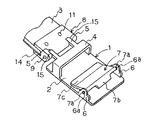
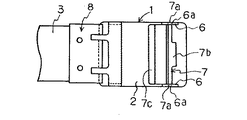
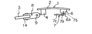
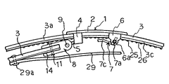
本実施例のバックル1は、図1、図2または図3に示すように、方形板状のバックル本体2の裏側の一端にベルト3を挿通する起立枠4を有すると共に、起立枠4の上辺の離間位置には2個のフック5、5が形成され、バックル本体2の裏側の他端にはベルト3を挿通し得る幅で設けられた一対の起立片6、6が形成され、これらの起立片6、6間に係止金具7が回動自在に形成されている。
The buckle 1 of this embodiment has an
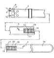
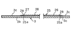
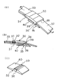
上記の構成において、図4(図4のホルダ8側は表側を図示し、ベルト3の自由端側は裏側を図示してある)に示すように、ベルト3は少なくとも2枚の皮製帯又は合成樹脂製帯等を重ね合わせて接着すると共に周縁付近を糸で縫合してなり、ベルト3の端部をホルダ8に設けられた挿着溝14(図1参照)に挿着して中空リベット11で固定することにより接続している。
In the above configuration, as shown in FIG. 4 (the
また、図1に示すように、ホルダ8の端部にはバックル1に設けられた2個のフック5、5を挿入する幅で係止溝15、15が形成されると共に、ホルダ8の端部の幅方向には夫々の係止溝15、15を貫く挿通孔に係止軸9が挿入され、夫々の係止溝15、15においてバックル1の各フック5、5を係止軸9に係止することにより、ベルト3をホルダ8に接続し、また各フック5、5を係止軸9から解除することにより、ベルト3をホルダ8から取り外すことができる。
Further, as shown in FIG. 1,
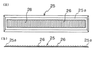
また、図4に示すように、ベルト3の挿入側の適当位置にはバックルアジャスタ25が設けられている。図6(a)又は(b)において、バックルアジャスタ25はナイロン6等の合成樹脂からなり、ベルト3よりも細幅の帯形状を有し、周囲に平板部25aが形成されると共に、その平板部25a内にて短幅方向に形成された凹溝26を長手方向に複数形成している。
Further, as shown in FIG. 4, a
このバックルアジャスタ25はベルト3の表側材3bと裏側材3cとの間に挿着され、図4又は図5に示すようにベルト3の裏側材3cに形成した開口27からバックルアジャスタ25の凹溝26の形成部を露呈すると共に、バックルアジャスタ25の平板部25aを開口27の周縁近傍にて糸28で縫合したことによって固定している。
The
また、図1に示すように、バックル本体1の一対の起立片6、6に回動自在に設けられた係止金具7は、夫々の起立片6、6に形成された係止穴6a、6aに係止される係止突起7a、7aを両側に有すると共に、一端側に突出した係止部7bがベルト3のバックルアジャスタ25の凹溝26に係止される幅を有する一方、両側の係止突起7a、7aを境に折曲して反対側に延長した回動作用片7cが先端付近を傾斜状に起立してあり、該回動作用片7cを起立する際の操作を容易にしている。
Further, as shown in FIG. 1, locking
このような構成により、係止金具7は、回動作用片7cの起立操作によってバックルアジャスタ25の凹溝26に対する係止部7bの係止を解除し、また回動作用片7cの倒伏操作によって係止部7cを凹溝26に係止するようにしている。
With such a configuration, the
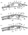
即ち、上記のように構成されたバックル1に、図7に示すようにベルト3を挿通して所定長さで固定するには、図8(a)に示すように、係止金具7を起立方向へ回動することによってベルト挿入通路23を開放した状態にしておき、このベルト挿入通路23にベルト3の自由端3aを挿入する。次いで、図8(b)に示すように、係止金具7の回動作用片7cを倒伏方向に回動操作して係止部7bの端部をベルト3のバックルアジャスタ25に形成された所望の凹溝26に係止して、図8(c)に示すように、係止金具7の回動作用片7cをバックルアジャスタ25に接触する付近まで倒伏する。
That is, in order to insert the
このような状態において、図8(c)に示すように、係止金具7の係止部7bは起立片6の係止穴6aを垂下した部位を越す位置にあって、ベルト3を身体に挿着した状態で矢印方向に引張力が作用すると、バックルアジャスタ25の凹溝26に係止された係止金具7の係止部7bは起立片6の係止穴6aに係合された係止突起7a(図6参照)によって回動を阻止する負荷が生じ、上記の引張力に対する大なる抵抗を発揮することとなる。
In such a state, as shown in FIG. 8 (c), the
ちなみに、バックルアジャスタ25をマジックテープ(商標名)で形成してベルト3の裏側に縫合したものと、本実施によるバックルアジャスタ25との引張力に対する耐力を比較した実験の結果、本実施例の場合、113kgfの引張力で係止金具7の係止部7bがバックルアジャスタ25の凹溝26から脱落したが、バックルアジャスタとして上記のマジックテープを使用した場合、36.5kgfの引張力で脱落したことから判断すると、本実施例のほうが、約3倍の引張力に耐える構造を有していることが明らかである。
By the way, as a result of an experiment comparing the
なお、図7に示すように、ベルト3におけるバックル1を接続した側の端部にバックル受片29の一端をリベット29a等で固定し、このバックル受片29がバックル1の裏側を覆うようにした保護構造とするのが好ましい。
As shown in FIG. 7, one end of the
本発明は、電気工事、警備員或いは警察官の職務等に使用する場合のように、ベルトに重い物品を吊り下げることでバックルに大きな引張力が作用する場合でも、強大な係止力を発揮することによって、ベルトの緩みを防止するバックルアジャスタとして利用することができる。 The present invention exerts a strong locking force even when a large tensile force acts on the buckle by suspending a heavy article on the belt, such as when used for electrical work, duties of a guard or police officer. By doing so, it can be used as a buckle adjuster for preventing the belt from loosening.
1…バックル
2…バックル本体
3…ベルト
3b…表側材
3c…裏側材
4…起立枠
5…フック
6…起立片
6a…係止穴
7…係止金具
7a…係止突起
7b…係止部
7c…回動作用片
8…ホルダ
9…係止軸
11…中空リベット
14…挿着溝
15…係止溝
23…ベルト挿入通路
25…バックルアジャスタ
26…凹溝
27…開口
28…糸
29…バックル受片
29a…リベット
DESCRIPTION OF SYMBOLS 1 ...
Claims (2)
該バックルアジャスタは合成樹脂からなり、前記ベルトの自由端側の裏側に設けられた帯形状を有すると共に、該帯形状の短幅方向に形成された凹溝を長手方向に所定間隔で複数形成してなり、前記係止金具に形成された係止部を前記バックルアジャスタの任意の凹溝に係止したり該凹溝から解除することによって、前記ベルトを所定長さに固定するようにしたことを特徴とするバックルアジャスタ。 The end of the belt is connected to one end on the back side of the buckle body, and the locking bracket is rotatable on a pair of upright pieces provided with a width that allows the belt to be inserted into the other end on the back side of the buckle body. In a buckle adjuster for fixing a belt that is to be inserted into a buckle provided at a predetermined length,
The buckle adjuster is made of synthetic resin and has a belt shape provided on the back side of the free end of the belt, and a plurality of concave grooves formed in the short width direction of the belt shape at a predetermined interval in the longitudinal direction. The belt is fixed to a predetermined length by locking or releasing the locking portion formed on the locking bracket in an arbitrary groove of the buckle adjuster. A buckle adjuster characterized by
The concave groove side of the buckle adjuster is exposed from the opening formed in the back side material of the belt, and is attached by sewing the vicinity of the outer periphery of the buckle adjuster to the vicinity of the peripheral edge of the opening of the back side material of the belt. The buckle adjuster according to claim 1.
Priority Applications (1)
| Application Number | Priority Date | Filing Date | Title |
|---|---|---|---|
| JP2004117466A JP2005296370A (en) | 2004-04-13 | 2004-04-13 | Buckle adjuster |
Applications Claiming Priority (1)
| Application Number | Priority Date | Filing Date | Title |
|---|---|---|---|
| JP2004117466A JP2005296370A (en) | 2004-04-13 | 2004-04-13 | Buckle adjuster |
Publications (1)
| Publication Number | Publication Date |
|---|---|
| JP2005296370A true JP2005296370A (en) | 2005-10-27 |
Family
ID=35328630
Family Applications (1)
| Application Number | Title | Priority Date | Filing Date |
|---|---|---|---|
| JP2004117466A Pending JP2005296370A (en) | 2004-04-13 | 2004-04-13 | Buckle adjuster |
Country Status (1)
| Country | Link |
|---|---|
| JP (1) | JP2005296370A (en) |
Cited By (2)
| Publication number | Priority date | Publication date | Assignee | Title |
|---|---|---|---|---|
| JP2010270413A (en) * | 2009-05-21 | 2010-12-02 | Yamamoto Sealing Kogyo Kk | Waist belt |
| CN111904106A (en) * | 2020-09-08 | 2020-11-10 | 广东豪顿服饰有限公司 | Novel police antiskid inner waistband |
-
2004
- 2004-04-13 JP JP2004117466A patent/JP2005296370A/en active Pending
Cited By (2)
| Publication number | Priority date | Publication date | Assignee | Title |
|---|---|---|---|---|
| JP2010270413A (en) * | 2009-05-21 | 2010-12-02 | Yamamoto Sealing Kogyo Kk | Waist belt |
| CN111904106A (en) * | 2020-09-08 | 2020-11-10 | 广东豪顿服饰有限公司 | Novel police antiskid inner waistband |
Similar Documents
| Publication | Publication Date | Title |
|---|---|---|
| US5490309A (en) | Fastener assembly | |
| US10178899B2 (en) | Slider for slide fastener | |
| US4862563A (en) | Securing strap and fastener | |
| US6622355B2 (en) | Mounting structure | |
| TWI296192B (en) | Shoelace buckle | |
| TW201223476A (en) | Cam lock buckle | |
| JP2017512512A (en) | connector | |
| KR20090117920A (en) | Multiple ball lock cable ties with retaining tension | |
| JPH11113611A (en) | Fastening tool | |
| US20080184538A1 (en) | Zip tie anchor | |
| US4917337A (en) | Article support for pegboards of alternate thickness | |
| US3696471A (en) | Releasable buckle | |
| US1763100A (en) | Belt buckle | |
| CN102573555A (en) | Buckle | |
| JP2005296370A (en) | Buckle adjuster | |
| TWI461159B (en) | Buckle | |
| US20070261212A1 (en) | Helmet holder | |
| US20030131451A1 (en) | Dual action locking buckle device | |
| JP2019201994A (en) | Buckle for garment belt | |
| US4901408A (en) | Means for fastening suspenders to a garment or other article of clothing | |
| JP3895318B2 (en) | buckle | |
| US312679A (en) | Harness-loop clamp | |
| JP4780280B2 (en) | Fastener | |
| JP2010270413A (en) | Waist belt | |
| EP2517589A1 (en) | Buckle |
Legal Events
| Date | Code | Title | Description |
|---|---|---|---|
| A977 | Report on retrieval |
Free format text: JAPANESE INTERMEDIATE CODE: A971007 Effective date: 20060405 |
|
| A131 | Notification of reasons for refusal |
Effective date: 20060410 Free format text: JAPANESE INTERMEDIATE CODE: A131 |
|
| A521 | Written amendment |
Free format text: JAPANESE INTERMEDIATE CODE: A523 Effective date: 20060530 |
|
| A131 | Notification of reasons for refusal |
Effective date: 20070703 Free format text: JAPANESE INTERMEDIATE CODE: A131 |
|
| A02 | Decision of refusal |
Effective date: 20071102 Free format text: JAPANESE INTERMEDIATE CODE: A02 |