JP2005296084A - Bipolar high-frequency treatment instrument for endoscope - Google Patents
Bipolar high-frequency treatment instrument for endoscope Download PDFInfo
- Publication number
- JP2005296084A JP2005296084A JP2004112610A JP2004112610A JP2005296084A JP 2005296084 A JP2005296084 A JP 2005296084A JP 2004112610 A JP2004112610 A JP 2004112610A JP 2004112610 A JP2004112610 A JP 2004112610A JP 2005296084 A JP2005296084 A JP 2005296084A
- Authority
- JP
- Japan
- Prior art keywords
- pair
- binding member
- insulating
- conductors
- covered
- Prior art date
- Legal status (The legal status is an assumption and is not a legal conclusion. Google has not performed a legal analysis and makes no representation as to the accuracy of the status listed.)
- Granted
Links
Images
Landscapes
- Surgical Instruments (AREA)
Abstract
【課題】可撓性シース内に配置される一対の導線とそれに被覆された絶縁チューブの双方を、容易な組み立て作業により導線どうしが短絡しないように先端近傍で確実に結束された状態にすることができる内視鏡用バイポーラ型高周波処置具を提供すること。
【解決手段】一対の導線6A,6Bを可撓性シース1の先端近傍において結束するための電気絶縁性の結束部材8を設けて、結束部材8には一対の導線6A,6Bが通過する一対の平行な貫通孔9A,9Bを形成し、結束部材8の先側に隣接する側では一方の導線6Aのみに絶縁チューブ7A1を被覆すると共に、結束部材8の後側に隣接する側では他方の導線6Bのみに絶縁チューブ7B1を被覆し、各絶縁チューブ7A1,7B1を各々結束部材8の貫通孔9A,9Bの途中位置まで差し込んで、各導線6A,6Bと絶縁チューブ7A1,7B1とを各々貫通孔9A,9B,10A,10Bに接合した。
【選択図】 図1An object of the present invention is to make sure that a pair of conductors arranged in a flexible sheath and an insulating tube covered by the conductors are securely bound in the vicinity of the tip so that the conductors are not short-circuited by an easy assembly operation. To provide a bipolar high-frequency treatment instrument for an endoscope.
An electrically insulating bundling member for bundling a pair of conductors 6A, 6B in the vicinity of the distal end of a flexible sheath 1 is provided, and the bundling member 8 is a pair through which a pair of conductors 6A, 6B passes. The parallel through-holes 9A and 9B are formed, and on the side adjacent to the front side of the binding member 8, only one conductor 6A is covered with the insulating tube 7A1, and on the side adjacent to the rear side of the binding member 8, the other side Only the conducting wire 6B is covered with the insulating tube 7B1, and the insulating tubes 7A1 and 7B1 are respectively inserted into the through holes 9A and 9B of the binding member 8 so as to pass through the conducting wires 6A and 6B and the insulating tubes 7A1 and 7B1. It joined to hole 9A, 9B, 10A, 10B.
[Selection] Figure 1
Description
この発明は、可撓性シースの先端に互いに電気絶縁された一対の電極が配置された内視鏡用バイポーラ型高周波処置具に関する。 The present invention relates to a bipolar high-frequency treatment instrument for an endoscope in which a pair of electrodes that are electrically insulated from each other are arranged at the distal end of a flexible sheath.
内視鏡用バイポーラ型高周波処置具においては、一般に、可撓性シースの先端に互いに電気絶縁された一対の電極が可動に配置され、その一対の電極を動作させるために可撓性シース内に軸線方向に進退自在に全長にわたって挿通配置された操作ワイヤが、各電極に高周波電流を通電するための互いに電気絶縁された一対の導線によって形成されている。即ち、一対の導線が操作ワイヤを兼用している(例えば、特許文献1、2)。
可撓性シース内に挿通されている一対の導線を操作ワイヤとして兼用する構造においては、一対の導線が先端においてバラバラに進退すると一対の電極の動作が不均一になって処置操作等に不都合が生じるので、一対の導線を先端近傍で結束しておくことが望ましい。 In a structure in which a pair of conducting wires inserted into the flexible sheath is also used as an operation wire, if the pair of conducting wires advance and retreat apart at the tip, the operation of the pair of electrodes becomes non-uniform, which is inconvenient for treatment operation and the like. Because of this, it is desirable to bind a pair of conducting wires near the tip.
しかし、そのような一対の導線には互いの間を電気絶縁するために絶縁チューブが被覆されており、絶縁チューブどうしを結束しても、その内部で絶縁チューブと導線との間に滑りが生じることによって一対の導線がバラバラに進退してしまう可能性がある。 However, such a pair of conducting wires is covered with an insulating tube to electrically insulate each other, and even if the insulating tubes are bound together, a slip occurs between the insulating tube and the conducting wire inside. As a result, there is a possibility that the pair of conductors may move forward and backward.
したがって、結束部では絶縁チューブを剥いで導線どうしを直接結束する必要があるが、単純にそのように構成すると、導線どうしが触れ易い状態になって電気的に短絡してしまう可能性が生じる。 Therefore, it is necessary to peel the insulating tube and bind the conductors directly at the bundling portion. However, if simply configured as such, there is a possibility that the conductors are easily touched and electrically short-circuited.
そこで本発明は、可撓性シース内に配置される一対の導線とそれに被覆された絶縁チューブの双方を、容易な組み立て作業により導線どうしが短絡しないように先端近傍で確実に結束された状態にすることができる内視鏡用バイポーラ型高周波処置具を提供することを目的とする。 Therefore, the present invention ensures that both the pair of conductors arranged in the flexible sheath and the insulating tube covered therewith are securely bound in the vicinity of the tip so that the conductors are not short-circuited by an easy assembly operation. An object of the present invention is to provide a bipolar high-frequency treatment instrument for an endoscope that can be used.
上記の目的を達成するため、本発明の内視鏡用バイポーラ型高周波処置具は、可撓性シースの先端に互いに電気絶縁された一対の電極が可動に配置され、一対の電極を動作させるために可撓性シース内に軸線方向に進退自在に全長にわたって挿通配置された操作ワイヤが、各電極に高周波電流を通電するための互いに電気絶縁された一対の導線である内視鏡用バイポーラ型高周波処置具において、一対の導線を可撓性シースの先端近傍において結束するための電気絶縁性の結束部材を設けて、結束部材には一対の導線が通過する一対の平行な貫通孔を形成し、結束部材の先側に隣接する側では一対の導線の中の一方の導線のみに電気絶縁性の絶縁チューブを被覆すると共に、結束部材の後側に隣接する側では他方の導線のみに電気絶縁性の絶縁チューブを被覆し、各絶縁チューブを各々結束部材の貫通孔の途中位置まで差し込んで、各導線と絶縁チューブとを各々貫通孔に接合したものである。 In order to achieve the above object, the bipolar high-frequency treatment instrument for endoscope according to the present invention is configured such that a pair of electrodes electrically insulated from each other is movably disposed at the distal end of a flexible sheath, and the pair of electrodes are operated. Bipolar high-frequency for endoscopes, in which an operation wire, which is inserted through the entire length of the flexible sheath so as to be capable of moving back and forth in the axial direction, is a pair of electrically insulated wires for supplying a high-frequency current to each electrode. In the treatment instrument, an electrically insulating binding member for binding the pair of conductors in the vicinity of the distal end of the flexible sheath is provided, and the binding member is formed with a pair of parallel through holes through which the pair of conductors pass. On the side adjacent to the front side of the binding member, only one of the pair of wires is covered with an electrically insulating insulating tube, and on the side adjacent to the rear side of the binding member, only the other conductor is electrically insulating. Extinction Coating the tube, insert halfway position of the through-hole of each binding member each insulating tube is obtained by bonding to each through hole and each conductor and the insulating tube.
本発明によれば、結束部材の先側に隣接する側では一対の導線の中の一方の導線のみに電気絶縁性の絶縁チューブを被覆すると共に、結束部材の後側に隣接する側では他方の導線のみに電気絶縁性の絶縁チューブを被覆し、各絶縁チューブを各々結束部材の貫通孔の途中位置まで差し込んで、各導線と絶縁チューブとを各々貫通孔に接合したことにより、可撓性シース内に配置される一対の導線とそれに被覆された絶縁チューブの双方を、容易な組み立て作業により導線どうしが短絡しないように先端近傍において確実に結束された状態にすることができる。 According to the present invention, on the side adjacent to the front side of the binding member, only one of the pair of conductive wires is covered with the electrically insulating tube, and on the side adjacent to the rear side of the binding member, the other side is covered. A flexible sheath is obtained by covering only the conducting wire with an electrically insulating insulating tube, inserting each insulating tube to a middle position of the through hole of the binding member, and joining each conducting wire and the insulating tube to each through hole. Both the pair of conductors arranged inside and the insulating tube covered with the conductors can be surely bound in the vicinity of the tip so that the conductors are not short-circuited by an easy assembly operation.
可撓性シースの先端に互いに電気絶縁された一対の電極が可動に配置され、一対の電極を動作させるために可撓性シース内に軸線方向に進退自在に全長にわたって挿通配置された操作ワイヤが、各電極に高周波電流を通電するための互いに電気絶縁された一対の導線である内視鏡用バイポーラ型高周波処置具において、一対の導線を可撓性シースの先端近傍において結束するための電気絶縁性の結束部材を設けて、結束部材には一対の導線が通過する一対の平行な貫通孔を形成し、結束部材の先側に隣接する側では一対の導線の中の一方の導線のみに電気絶縁性の絶縁チューブを被覆すると共に、結束部材の後側に隣接する側では他方の導線のみに電気絶縁性の絶縁チューブを被覆し、各絶縁チューブを各々結束部材の貫通孔の途中位置まで差し込んで、各導線と絶縁チューブとを各々貫通孔に接合する。 A pair of electrodes that are electrically insulated from each other are movably disposed at the distal end of the flexible sheath, and an operation wire is inserted through the entire length of the flexible sheath so as to be able to advance and retract in the axial direction in order to operate the pair of electrodes. In a bipolar high-frequency treatment instrument for endoscope, which is a pair of electrically insulated wires for energizing each electrode with a high-frequency current, electrical insulation for binding the pair of wires in the vicinity of the distal end of the flexible sheath The binding member is provided with a pair of parallel through holes through which the pair of conductors pass, and only one of the pair of conductors is electrically connected to the side adjacent to the front side of the binding member. Cover the insulating insulating tube, and on the side adjacent to the rear side of the bundling member, cover only the other conductor with the electrically insulating insulating tube, and place each insulating tube in the middle of the through hole of the bundling member. They crowded and, joined to each through hole and each conductor and the insulating tube.
図面を参照して本発明の実施例を説明する。
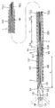
図1は内視鏡用バイポーラ型高周波処置具を示しており、図示されていない内視鏡の処置具挿通チャンネルに挿脱自在な例えば四フッ化エチレン樹脂チューブ等によって形成された電気絶縁性の可撓性シース1の先端に、電気絶縁性の例えばセラミックスや耐熱プラスチック等からなる先端支持本体2が取着されている。
Embodiments of the present invention will be described with reference to the drawings.
FIG. 1 shows a bipolar high-frequency treatment instrument for an endoscope, which is an electrically insulating material formed by, for example, a tetrafluoroethylene resin tube that can be inserted into and removed from a treatment instrument insertion channel of an endoscope (not shown). A distal
先端支持本体2の先端部分には、導電性の例えばステンレス鋼等からなる一対の嘴状の電極3A,3Bが、互いに電気絶縁された状態で各々支軸4A,4Bを中心に回動自在に取り付けられている。
A pair of hook-
そして、各電極3A,3Bから一体的に支軸4A,4Bの後方に延出するように形成されたアーム5A,5Bが、先端支持本体2に形成されているスリット2a内に配置されていて、可撓性シース1内に全長にわたって挿通配置された一対の導線6A,6Bの先端がアーム5A,5Bに連結されている。
The
一対の導線6A,6Bは可撓性シース1内に軸線方向に進退自在に配置されており、可撓性シース1の基端側に連結された図示されていない操作部から導線6A,6Bを進退操作することにより、導線6A,6Bが進退動作をし、それによって電極3A,3Bが嘴状に開閉する。図1には、電極3A,3Bが開いた状態が二点鎖線で図示されている。
The pair of
このように一対の導線6A,6Bは電極3A,3Bを開閉駆動するための操作ワイヤを兼用しているが、各電極3A,3Bに操作部側から高周波電流を通電することができるよう、一対の導線6A,6Bは互いに電気絶縁された状態で電極3A,3Bに接続されている。
As described above, the pair of
7A1と7A2は、一方の導線6Aに被覆された電気絶縁性の絶縁チューブ、7B1と7B2は、他方の導線6Bに被覆された電気絶縁性の絶縁チューブであり、一方の導線6Aと他方の導線6Bとが直接接触しないようにしてある。
7A1 and 7A2 are electrically insulating insulating tubes covered with one conducting
また、一対の導線6A,6Bは先端近傍において絶縁チューブ7A1,7B1と共に結束部材8により結束されている。各導線6A,6Bの先端から結束部材8までの距離Lは、例えば10〜20mm程度である。
Further, the pair of
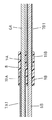
結束部材8は、電気絶縁性のプラスチック部材又はセラミックス等により可撓性シース1内に緩く嵌合する例えば円柱形状に形成されていて、その部分を拡大図示する図2にも示されるように、結束部材8には、一対の導線6A,6Bが通過する一対の平行な貫通孔9A,9Bが軸線方向に形成されている。
The
そして、結束部材8の先側に隣接する側では、一対の導線6A,6Bの中の一方の導線6Aのみに絶縁チューブ7A1が被覆されていて、それと並んで配置されている他方の導線6Bは可撓性シース1内において剥き出しである。
Then, on the side adjacent to the front side of the
また、結束部材8の後側に隣接する側では他方の導線6Bのみに絶縁チューブ7B1が被覆されていて、それと並んで配置されている一方の導線6Aは可撓性シース1内において剥き出しである。
In addition, on the side adjacent to the rear side of the
そのように、結束部材8の前側において一方の導線6Aに被覆されている絶縁チューブ7A1と、結束部材8の後側において他方の導線6Bに被覆されている絶縁チューブ7B1とを、各々貫通孔9A,9Bの途中位置まで差し込めるように、各貫通孔9A,9Bには太径部10A,10Bが形成されている。ただし、太径部10A,10Bどうしが干渉しないように、太径部10A,10Bの長さは結束部材8の長さの半分未満に設定されている。
In this way, the insulating tube 7A1 that is covered with one
そして、各太径部10A,10B内においては、絶縁チューブ7A1,7B1が結束部材8に接着固定され、貫通孔9A,9Bのその他の部分内においては、導線6A,6Bが結束部材8に直接接着固定されている。
In each of the
したがって、極めて容易な組み立て作業により、各導線6A,6Bと絶縁チューブ7A1,7B1とを各々結束部材8に対して確実に接着固定することができ、操作ワイヤとしての一対の導線6A,6Bを、先端部分において動きがバラバラにならないように均一に進退させることができる。
Therefore, the conducting
また、結束部材8より後方において一対の導線6A,6Bどうしの電気絶縁状態を確保するために、各導線6A,6Bには各々操作部に至る長い絶縁チューブ7A2,7B2が被覆されている。
Further, in order to ensure an electrical insulation state between the pair of
ただし、可撓性シース1が屈曲したときに操作部に至る絶縁チューブ7A2,7B2と導線6A,6Bとの間に滑りが生じることを考慮して、操作部に至る絶縁チューブ7A2,7B2の先端面と結束部材8の後端面(及び結束部材8の後側に固着されている絶縁チューブ7B1の後端面)との間には、軸線方向に各々数mm程度の隙間SA,SBをあけてある。
However, in consideration of the occurrence of slipping between the insulating tubes 7A2 and 7B2 reaching the operating portion and the conducting
そして、その両導線6A,6Bの被覆の隙間SAと隙間SBとの間の間隔Mが、30〜50mm程度に設定されていることにより、操作部に至る絶縁チューブ7A2,7B2が導線6A,6Bに対して滑っても、導線6A,6B間の電気絶縁が確実に確保されている。
And since the space | interval M between the clearance gap SA and clearance gap SB of the both conducting
なお本発明は上記実施例に限定されるものではなく、例えば本発明は電極3A,3Bが嘴状以外の動作をする各種の内視鏡用バイポーラ型高周波処置具に適用することができる。
The present invention is not limited to the above-described embodiments. For example, the present invention can be applied to various types of bipolar high-frequency treatment instruments for endoscopes in which the
1 可撓性シース
3A,3B 電極
6A,6B 導線
7A1,7B1 結束部材に結束される絶縁チューブ
7A2,7B2 操作部に至る絶縁チューブ
8 結束部材
9A,9B 貫通孔
10A,10B 太径部
DESCRIPTION OF SYMBOLS 1
Claims (1)
上記一対の導線を上記可撓性シースの先端近傍において結束するための電気絶縁性の結束部材を設けて、上記結束部材には上記一対の導線が通過する一対の平行な貫通孔を形成し、上記結束部材の先側に隣接する側では上記一対の導線の中の一方の導線のみに電気絶縁性の絶縁チューブを被覆すると共に、上記結束部材の後側に隣接する側では他方の導線のみに電気絶縁性の絶縁チューブを被覆し、上記各絶縁チューブを各々上記結束部材の貫通孔の途中位置まで差し込んで、上記各導線と絶縁チューブとを各々上記貫通孔に接合したことを特徴とする内視鏡用バイポーラ型高周波処置具。 An operation in which a pair of electrodes electrically insulated from each other is movably disposed at the distal end of the flexible sheath, and is inserted through the entire length of the flexible sheath so as to be movable back and forth in the axial direction in order to operate the pair of electrodes. In the bipolar high-frequency treatment instrument for an endoscope, wherein the wire is a pair of electrically insulated wires for supplying a high-frequency current to each of the electrodes,
Providing an electrically insulating binding member for binding the pair of conducting wires in the vicinity of the distal end of the flexible sheath, and forming a pair of parallel through holes through which the pair of conducting wires pass in the binding member; On the side adjacent to the front side of the binding member, only one of the pair of conductive wires is covered with an electrically insulating insulating tube, and on the side adjacent to the rear side of the binding member, only the other conductive wire is covered. An insulating tube that is electrically insulative is covered, and each of the insulating tubes is inserted halfway through the through hole of the binding member, and the conductive wire and the insulating tube are joined to the through hole, respectively. Bipolar high-frequency treatment tool for endoscope.
Priority Applications (1)
| Application Number | Priority Date | Filing Date | Title |
|---|---|---|---|
| JP2004112610A JP4459688B2 (en) | 2004-04-07 | 2004-04-07 | Bipolar high-frequency treatment instrument for endoscope |
Applications Claiming Priority (1)
| Application Number | Priority Date | Filing Date | Title |
|---|---|---|---|
| JP2004112610A JP4459688B2 (en) | 2004-04-07 | 2004-04-07 | Bipolar high-frequency treatment instrument for endoscope |
Publications (2)
| Publication Number | Publication Date |
|---|---|
| JP2005296084A true JP2005296084A (en) | 2005-10-27 |
| JP4459688B2 JP4459688B2 (en) | 2010-04-28 |
Family
ID=35328365
Family Applications (1)
| Application Number | Title | Priority Date | Filing Date |
|---|---|---|---|
| JP2004112610A Expired - Lifetime JP4459688B2 (en) | 2004-04-07 | 2004-04-07 | Bipolar high-frequency treatment instrument for endoscope |
Country Status (1)
| Country | Link |
|---|---|
| JP (1) | JP4459688B2 (en) |
Cited By (1)
| Publication number | Priority date | Publication date | Assignee | Title |
|---|---|---|---|---|
| JP2010082298A (en) * | 2008-10-01 | 2010-04-15 | Hoya Corp | Bipolar high-frequency snare for endoscope |
-
2004
- 2004-04-07 JP JP2004112610A patent/JP4459688B2/en not_active Expired - Lifetime
Cited By (1)
| Publication number | Priority date | Publication date | Assignee | Title |
|---|---|---|---|---|
| JP2010082298A (en) * | 2008-10-01 | 2010-04-15 | Hoya Corp | Bipolar high-frequency snare for endoscope |
Also Published As
| Publication number | Publication date |
|---|---|
| JP4459688B2 (en) | 2010-04-28 |
Similar Documents
| Publication | Publication Date | Title |
|---|---|---|
| JP4420593B2 (en) | Bipolar high-frequency treatment instrument for endoscope | |
| JP4295925B2 (en) | Bipolar high-frequency treatment instrument for endoscope | |
| US6953430B2 (en) | Pincerlike instrument for endoscope | |
| JP5114179B2 (en) | Bipolar high-frequency treatment instrument for endoscope | |
| US20120016190A1 (en) | Endoscope treatment instrument | |
| JP2003504109A (en) | Movable ablation electrode | |
| US20040015165A1 (en) | Treatment tool for endoscope having end effector operating like pincers | |
| JP4321842B2 (en) | Bipolar high-frequency treatment instrument for endoscope | |
| JP4459688B2 (en) | Bipolar high-frequency treatment instrument for endoscope | |
| JP2010179009A (en) | High-frequency treatment tool for endoscope | |
| JP4423474B2 (en) | End of the forceps for endoscope | |
| JP5137758B2 (en) | Bipolar high-frequency treatment instrument for endoscope | |
| US20230010005A1 (en) | Plasma Probe And Method For Assembly Of Its Electrode | |
| JP4459692B2 (en) | Bipolar high-frequency treatment instrument for endoscope | |
| JP4321853B2 (en) | Endoscopic high-frequency snare | |
| JP2009022623A (en) | Bipolar high-frequency treating instrument for endoscope | |
| JP2009207666A (en) | Bipolar type high frequency incision device for endoscope | |
| JP4130942B2 (en) | Bipolar high-frequency treatment instrument for endoscope | |
| JP5854912B2 (en) | Endoscopic high-frequency treatment instrument | |
| JP5952068B2 (en) | Endoscopic high-frequency treatment instrument | |
| JP2012100863A (en) | Treatment tool for endoscope | |
| JPH11155876A (en) | Forceps type electric treatment instrument | |
| JP4554797B2 (en) | Endoscopic high-frequency snare | |
| JP4554796B2 (en) | Endoscopic high frequency snare | |
| JP2007229294A (en) | Bipolar saddle-shaped high-frequency treatment instrument for endoscope |
Legal Events
| Date | Code | Title | Description |
|---|---|---|---|
| A621 | Written request for application examination |
Free format text: JAPANESE INTERMEDIATE CODE: A621 Effective date: 20070315 |
|
| A711 | Notification of change in applicant |
Free format text: JAPANESE INTERMEDIATE CODE: A712 Effective date: 20080501 |
|
| TRDD | Decision of grant or rejection written | ||
| A01 | Written decision to grant a patent or to grant a registration (utility model) |
Free format text: JAPANESE INTERMEDIATE CODE: A01 Effective date: 20100121 |
|
| A01 | Written decision to grant a patent or to grant a registration (utility model) |
Free format text: JAPANESE INTERMEDIATE CODE: A01 |
|
| A61 | First payment of annual fees (during grant procedure) |
Free format text: JAPANESE INTERMEDIATE CODE: A61 Effective date: 20100210 |
|
| R150 | Certificate of patent or registration of utility model |
Ref document number: 4459688 Country of ref document: JP Free format text: JAPANESE INTERMEDIATE CODE: R150 Free format text: JAPANESE INTERMEDIATE CODE: R150 |
|
| FPAY | Renewal fee payment (event date is renewal date of database) |
Free format text: PAYMENT UNTIL: 20130219 Year of fee payment: 3 |
|
| FPAY | Renewal fee payment (event date is renewal date of database) |
Free format text: PAYMENT UNTIL: 20130219 Year of fee payment: 3 |
|
| FPAY | Renewal fee payment (event date is renewal date of database) |
Free format text: PAYMENT UNTIL: 20140219 Year of fee payment: 4 |
|
| S531 | Written request for registration of change of domicile |
Free format text: JAPANESE INTERMEDIATE CODE: R313531 |
|
| R350 | Written notification of registration of transfer |
Free format text: JAPANESE INTERMEDIATE CODE: R350 |
|
| R250 | Receipt of annual fees |
Free format text: JAPANESE INTERMEDIATE CODE: R250 |
|
| R250 | Receipt of annual fees |
Free format text: JAPANESE INTERMEDIATE CODE: R250 |
|
| R250 | Receipt of annual fees |
Free format text: JAPANESE INTERMEDIATE CODE: R250 |
|
| R250 | Receipt of annual fees |
Free format text: JAPANESE INTERMEDIATE CODE: R250 |
|
| R250 | Receipt of annual fees |
Free format text: JAPANESE INTERMEDIATE CODE: R250 |
|
| R250 | Receipt of annual fees |
Free format text: JAPANESE INTERMEDIATE CODE: R250 |
|
| R250 | Receipt of annual fees |
Free format text: JAPANESE INTERMEDIATE CODE: R250 |
|
| R250 | Receipt of annual fees |
Free format text: JAPANESE INTERMEDIATE CODE: R250 |
|
| EXPY | Cancellation because of completion of term |