JP2005296032A - Bathing apparatus - Google Patents

Bathing apparatus Download PDF

Info

Publication number
JP2005296032A
JP2005296032A JP2004111945A JP2004111945A JP2005296032A JP 2005296032 A JP2005296032 A JP 2005296032A JP 2004111945 A JP2004111945 A JP 2004111945A JP 2004111945 A JP2004111945 A JP 2004111945A JP 2005296032 A JP2005296032 A JP 2005296032A
Authority
JP
Japan
Prior art keywords
bathtub
wheelchair
fixing
fixing means
hot water
Prior art date
Legal status (The legal status is an assumption and is not a legal conclusion. Google has not performed a legal analysis and makes no representation as to the accuracy of the status listed.)
Pending
Application number
JP2004111945A
Other languages
Japanese (ja)
Inventor
Toshiyuki Takagaki
俊之 高垣
Tsutomu Uchida
力 内田
Keiichi Ando
恵一 安藤
Current Assignee (The listed assignees may be inaccurate. Google has not performed a legal analysis and makes no representation or warranty as to the accuracy of the list.)
Og Giken Co Ltd
Original Assignee
Og Giken Co Ltd
Priority date (The priority date is an assumption and is not a legal conclusion. Google has not performed a legal analysis and makes no representation as to the accuracy of the date listed.)
Filing date
Publication date
Application filed by Og Giken Co Ltd filed Critical Og Giken Co Ltd
Priority to JP2004111945A priority Critical patent/JP2005296032A/en
Publication of JP2005296032A publication Critical patent/JP2005296032A/en
Pending legal-status Critical Current

Links

Images

Abstract

<P>PROBLEM TO BE SOLVED: To provide a bathing apparatus for which the fixing parts of a bathtub and a wheelchair are reduced, constitution relating to the fixing means of the bathtub and the wheelchair is simplified and a manufacturing cost is reduced as well. <P>SOLUTION: In the bathing apparatus, the bathtub 1 for which an opening part 2 is formed on one side and a hot water storage tank 13 are provided, the wheelchair 3 is inserted into the bathtub 1 from the opening part 2 and the opening part 2 is watertightly held by the wheelchair 3. The bathing apparatus is provided with a first fixing means 5 for fixing the left and right side walls 1a and 1b of the bathtub 1 and the left and right upper positions of the backrest part 4 of the wheelchair 3 and a second fixing means 6 for pressurizing and fixing the back surface lower part of the backrest part 4 of the wheelchair 3. <P>COPYRIGHT: (C)2006,JPO&NCIPI

Description

本発明は、一側方に開口部が形成された浴槽と貯湯槽とを有し、開口部から車椅子を浴槽内へ挿入し、開口部を車椅子で水密保持する入浴装置に関するものである。   The present invention relates to a bathing apparatus that has a bathtub and a hot water storage tank with an opening formed on one side, inserts a wheelchair into the bathtub from the opening, and holds the opening watertight with the wheelchair.

従来の浴槽の開口部を車椅子の背凭れ部で閉塞状態に保持する車椅子用の入浴装置として、実公平6−12791号公報が挙げられる。しかしながら、前記公報には、浴槽1の開口部5を入浴用車椅子2の背凭れ部18cで閉塞状態に保持する扉ロック機構に付いて具体的に記載されていない。   Japanese Utility Model Publication No. 6-12791 can be cited as a bathing apparatus for a wheelchair that keeps the opening of a conventional bathtub closed in the backrest of the wheelchair. However, the publication does not specifically describe the door lock mechanism that holds the opening 5 of the bathtub 1 in the closed state by the backrest 18 c of the bathing wheelchair 2.

又、特開平9−108290号公報の車椅子入浴装置に装備される封水保持装置41は、槽本体13の前面開口部12の両側それぞれの上下二箇所の位置、即ち全四箇所位置で車椅子21と浴槽11とをロックするものであり、ロック箇所が多く、故に、封水保持装置41が複雑で大掛りになり、介助者が行うロック作業も煩雑になるという問題点があった。
実公平6−12791号 特開平9−108290号
Further, the sealed water holding device 41 provided in the wheelchair bathing device disclosed in Japanese Patent Laid-Open No. 9-108290 has two positions on the upper and lower sides of the front opening 12 of the tank body 13, that is, all four positions. And the bathtub 11 are locked, and there are many lock portions. Therefore, there is a problem that the sealing water holding device 41 is complicated and large, and the lock work performed by the assistant becomes complicated.
No. 6-12791 JP-A-9-108290

本発明の目的は、上述の問題点を解決し、浴槽と車椅子との固定箇所を減少し浴槽の開口部を車椅子で水密保持する構成を簡素化すると共に、浴槽と車椅子との固定作業が容易に行える操作性を改善した入浴装置を提供することにある。   The object of the present invention is to solve the above-mentioned problems, reduce the number of fixing points between the bathtub and the wheelchair, simplify the structure for keeping the opening of the bathtub watertight with the wheelchair, and easily fix the bathtub and the wheelchair. An object of the present invention is to provide a bath apparatus with improved operability.

上記の目的を実現する為、本発明では、一側方に開口部2が形成された浴槽1と、貯湯槽13とを有し、開口部2から車椅子3を浴槽1内へ挿入し、開口部2を車椅子3で水密保持する入浴装置において、浴槽1の左右側壁1a・1bと車椅子3の背凭れ部4の左右側上部を固定する第一の固定手段5と、浴槽1の底壁1cと車椅子3の背凭れ部4の下部を固定する第二の固定手段6とを具備した。
そして、第一の固定手段5による固定機能を、車椅子3を浴槽1の内方所定位置にまで進入させると自動的に作動するものとし、第二の固定手段6による固定機能を、第一の固定手段5の固定機能が作動状態にある時のみ作動可能とされるものとした。
又、第一の固定手段5及び第二の固定手段6によって浴槽1と車椅子3とが固定された状態にある時のみ貯湯槽13から浴槽1への湯水移送を可能とした。
更に、第二の固定手段6による浴槽1と車椅子3との固定機能は、浴槽1内の湯水の水位が所定高さ位置未満の状態にある時のみ解除可能とされるものとした。
更に又、第一の固定手段5の固定機能を解除する操作手段12を、車椅子3の背凭れ部4の裏側面に設けた。
又、第一の固定手段5を、車椅子3の背凭れ部4の左右側面位置にそれぞれ進退移動可能に設けられたロックピン7と浴槽1の左右側壁1a・1bの内壁面に設けられた前記ロックピン7が嵌入する孔8とから構成し、第二の固定手段6を、浴槽1の下方外部に設けた電動アクチュエーター9と、該電動アクチュエーター9の伸縮自在なロッド10先端部と浴槽1の底壁1cとに軸着された押圧片11と、背凭れ部4の下端に設けられ押圧片11を受け止める受止部材50とから構成した。
更に、背凭れ部4の表側面に対するロックピン7の位置を調整する第一の調整手段47と、背凭れ部4の表側面に対する受止部材50の位置を調整する第二の調整手段48とを具備し、孔8の位置調整と、ロッド10の伸長量調整の少なくともどちらか一方を可能とした。
In order to achieve the above object, the present invention has a bathtub 1 having an opening 2 formed on one side, and a hot water storage tank 13. The wheelchair 3 is inserted into the bathtub 1 from the opening 2, and the opening is opened. In the bathing apparatus that holds the part 2 in a watertight manner with the wheelchair 3, the first fixing means 5 that fixes the left and right side walls 1 a and 1 b of the bathtub 1 and the left and right upper portions of the backrest part 4 of the wheelchair 3, and the bottom wall 1 c of the bathtub 1 And a second fixing means 6 for fixing the lower part of the backrest part 4 of the wheelchair 3.
Then, the fixing function by the first fixing means 5 is automatically activated when the wheelchair 3 is advanced to the predetermined position inside the bathtub 1, and the fixing function by the second fixing means 6 is It is assumed that it can be operated only when the fixing function of the fixing means 5 is in an operating state.
Further, only when the bathtub 1 and the wheelchair 3 are fixed by the first fixing means 5 and the second fixing means 6, hot water transfer from the hot water storage tank 13 to the bathtub 1 is made possible.
Furthermore, the fixing function between the bathtub 1 and the wheelchair 3 by the second fixing means 6 can be released only when the water level of the hot water in the bathtub 1 is less than the predetermined height position.
Furthermore, the operation means 12 for releasing the fixing function of the first fixing means 5 is provided on the back side surface of the backrest portion 4 of the wheelchair 3.
In addition, the first fixing means 5 is provided on the inner wall surface of the left and right side walls 1a and 1b of the bathtub 1 and the lock pin 7 that can be moved forward and backward at the left and right side positions of the backrest 4 of the wheelchair 3, respectively. It is composed of a hole 8 into which the lock pin 7 is inserted, and the second fixing means 6 is provided in the electric actuator 9 provided outside the lower part of the bathtub 1, the distal end of the telescopic rod 10 of the electric actuator 9, and the bathtub 1 The pressing piece 11 is pivotally attached to the bottom wall 1c, and the receiving member 50 is provided at the lower end of the backrest portion 4 and receives the pressing piece 11.
Furthermore, a first adjustment means 47 for adjusting the position of the lock pin 7 with respect to the front side surface of the backrest portion 4, and a second adjustment means 48 for adjusting the position of the receiving member 50 with respect to the front side surface of the backrest portion 4; The position adjustment of the hole 8 and the extension amount adjustment of the rod 10 were made possible.

本発明は、浴槽1の左右側壁1a・1bと車椅子3の背凭れ部4の左右側上部を固定する第一の固定手段5と、浴槽1の底壁1cと車椅子3の背凭れ部4の下部を固定する第二の固定手段6とを具備したものであるから、ロック箇所を全四箇所位置とした従来技術に比して、本発明では固定箇所を全三箇所位置に減少させることができ、更に、浴槽1内に給湯された湯圧に耐え、且つ湯を浴槽1外へ漏出させない為に最も効果的な固定箇所の配置とすることにより第一の固定手段6及び第二の固定手段6に係る構成を簡素化・小型化でき、故に製造コストも軽減できる。   The present invention relates to the first fixing means 5 for fixing the left and right side walls 1a and 1b of the bathtub 1 and the left and right upper portions of the backrest 4 of the wheelchair 3, the bottom wall 1c of the bathtub 1 and the backrest 4 of the wheelchair 3. Since the second fixing means 6 for fixing the lower part is provided, in the present invention, the fixing points can be reduced to all three positions as compared with the prior art in which the locking points are all four positions. In addition, the first fixing means 6 and the second fixing can be made by arranging the most effective fixing points in order to withstand the hot water pressure supplied into the bathtub 1 and prevent the hot water from leaking out of the bathtub 1. The configuration related to the means 6 can be simplified and miniaturized, and thus the manufacturing cost can be reduced.

本発明では、第一の固定手段5による固定機能を、車椅子3を浴槽1の内方所定位置にまで進入させると自動的に作動するものとしたので、浴槽1の左右側壁1a・1bと車椅子3の背凭れ部4の左右側上部との固定作業に特別な操作を必要とせず、容易に固定作業ができ、故に介助者の作業負担を軽減できる。又、入浴装置の操作に不慣れな介助者も容易に固定作業が行え、好都合である。   In the present invention, since the fixing function by the first fixing means 5 is automatically operated when the wheelchair 3 is moved to a predetermined position inside the bathtub 1, the left and right side walls 1a and 1b of the bathtub 1 and the wheelchair No special operation is required for fixing the left and right upper portions of the 3 backrest parts 4 and the fixing work can be easily performed. Therefore, the burden on the assistant can be reduced. Also, an assistant who is unfamiliar with the operation of the bathing apparatus can easily perform the fixing work, which is convenient.

本発明は、第二の固定手段6による固定機能が、第一の固定手段5の固定機能が作動状態にある時のみ作動可能とされるものであり、第一の固定手段5により浴槽1の左右側壁1a・1bと車椅子3の背凭れ部4の左右側上部とを固定し位置決めをした後、第二の固定手段6による浴槽1の底壁1cと車椅子3の背凭れ部4の下部との固定機能が作動可能とされるので、第一の固定手段5による前記固定が不十分な時に、第二の固定手段6を誤って作動させ車椅子3の不適切な箇所を固定した結果、車椅子3を破損してしまうといった不都合な事態を未然に防止することができる。
又、介助者は、第二の固定手段6による固定機能の作動開始時に、第一の固定手段5による固定機能が正常に作動していないことを確認でき、第一の固定手段5による固定が不十分なまま第二の固定手段6の固定操作を行うことはなく、故に、浴槽1と車椅子3との固定が不完全な場合に貯湯槽13から浴槽1への湯水移送を行い湯水を浴室に漏出してしまうといった不都合な事態を回避できる。
In the present invention, the fixing function by the second fixing means 6 can be operated only when the fixing function of the first fixing means 5 is in an operating state. After fixing the right and left side walls 1a and 1b and the left and right upper parts of the backrest part 4 of the wheelchair 3, the bottom wall 1c of the bathtub 1 and the lower part of the backrest part 4 of the wheelchair 3 by the second fixing means 6 As a result of the erroneous operation of the second fixing means 6 to fix an inappropriate portion of the wheelchair 3 when the fixing by the first fixing means 5 is insufficient, It is possible to prevent an inconvenient situation such as damaging 3.
Moreover, the assistant can confirm that the fixing function by the first fixing means 5 is not operating normally when the fixing function by the second fixing means 6 is started. The fixing operation of the second fixing means 6 is not performed in an insufficient state. Therefore, when the fixing between the bathtub 1 and the wheelchair 3 is incomplete, the hot water is transferred from the hot water tank 13 to the bathtub 1 and the hot water is taken into the bathroom. It is possible to avoid inconvenient situations such as leakage.

本発明は、第一の固定手段5及び第二の固定手段6によって浴槽1と車椅子3とが固定された状態にある時のみ貯湯槽13から浴槽1への湯水移送を可能としたものであるから、介助者は浴槽1と車椅子3との固定が不完全な場合に貯湯槽13から浴槽1への湯水移送を行い湯水を浴室に漏出してしまうといった不都合な事態を回避できる。   The present invention makes it possible to transfer hot water from the hot water tank 13 to the bathtub 1 only when the bathtub 1 and the wheelchair 3 are fixed by the first fixing means 5 and the second fixing means 6. Therefore, the assistant can avoid the inconvenient situation that the hot water is transferred from the hot water storage tank 13 to the bathtub 1 when the fixing between the bathtub 1 and the wheelchair 3 is incomplete, and the hot water is leaked into the bathroom.

本発明は、第二の固定手段6による浴槽1と車椅子3との固定機能が、浴槽1内の湯水の水位が所定高さ位置未満の状態にある時のみ解除されるものであるから、介助者が操作を誤り浴槽1内に湯水が多量に存在するにも拘らず第二の固定手段6の固定機能を解除させた結果、浴槽1内の湯水を浴室内へ漏出してしまうといった不都合な事態も回避できる。   In the present invention, the function of fixing the bathtub 1 and the wheelchair 3 by the second fixing means 6 is released only when the hot water level in the bathtub 1 is less than the predetermined height position. As a result of releasing the fixing function of the second fixing means 6 in spite of a large amount of hot water in the bathtub 1 being operated by the operator, the hot water in the bathtub 1 leaks into the bathroom. Things can be avoided.

本発明は、第一の固定手段5の固定機能を解除する操作手段12を、車椅子3の背凭れ部4の裏側位置に設けたものであるから、介助者が、第一の固定手段5の固定機能を解除する操作を車椅子3の背面側から簡単に操作でき、入退浴作業の妨げとならない。   In the present invention, since the operation means 12 for releasing the fixing function of the first fixing means 5 is provided at the back side position of the backrest part 4 of the wheelchair 3, The operation of releasing the fixing function can be easily performed from the back side of the wheelchair 3, and does not hinder the bathing work.

本発明は、第一の固定手段5を、車椅子3の背凭れ部4の左右側面位置にそれぞれ進退移動可能に設けられたロックピン7と浴槽1の左右側壁1a・1bの内壁面に設けられた前記ロックピン7が嵌入する孔8とから構成し、第二の固定手段6を、浴槽1の下方外部に設けた電動アクチュエーター9と、該電動アクチュエーター9の伸縮自在なロッド10先端部と浴槽1の底壁1cとに軸着された押圧片11と、背凭れ部4の下端に螺着され押圧片11を受け止める受止部材50とから構成したものであるから、従来技術の封水保持装置に比して、第一の固定手段5及び第二の固定手段6に係る構成を簡素化・小型化でき、故に製造コストも軽減できる。   In the present invention, the first fixing means 5 is provided on the inner wall surface of the right and left side walls 1a and 1b of the bathtub 1 and the lock pin 7 provided so as to be movable forward and backward at the left and right side positions of the backrest part 4 of the wheelchair 3, respectively. And the second fixing means 6 provided on the outside of the lower part of the bathtub 1, the tip of the telescopic rod 10 of the electric actuator 9 and the bathtub. 1 is composed of a pressing piece 11 pivotally attached to the bottom wall 1c and a receiving member 50 which is screwed to the lower end of the backrest 4 and receives the pressing piece 11. Compared with the apparatus, the configuration relating to the first fixing means 5 and the second fixing means 6 can be simplified and reduced in size, and thus the manufacturing cost can be reduced.

本発明は、背凭れ部4の表側面に対するロックピン7の位置を調整する第一の調整手段47を具備したものであるから、ロックピン7を浴槽1の孔8に嵌入した際に、浴槽1の開口部2の接合面53と背凭れ部2の表側面に形成される左・右平坦面64a・64bの上部との間に僅かな空隙が生じてしまった場合にも、ロックピン7の位置を微調整する、即ち、ロックピン7の位置を背凭れ部4の表側面から離間する方向に移動させることにより、接合面53と背凭れ部4の左・右平坦面64a・64bの上部とを当接させ容易に閉塞状態となすことができ、浴槽1内の湯水を浴室内に漏出してしまうといった不都合な事態が発生しない。
又、ロックピン7が背凭れ部4の表側面寄りの方向に位置する不適切な状態のまま入浴装置22を使用すると、接合面53に背凭れ部4を当接し閉塞状態とする際に、接合面53に貼着されたシール材23に過度の押圧力が加わり、シール材23の摩耗を促進してしまうといった問題が発生するが、本発明の構成によれば、ロックピン7の位置の微調整が可能なので、前記の問題を容易に解消することができる。
Since the present invention includes the first adjusting means 47 for adjusting the position of the lock pin 7 with respect to the front side surface of the backrest portion 4, when the lock pin 7 is fitted into the hole 8 of the bathtub 1, Even when a slight gap is formed between the joint surface 53 of the opening portion 1 of the first opening 2 and the upper portions of the left and right flat surfaces 64a and 64b formed on the front side surface of the backrest portion 2, the lock pin 7 Are adjusted, that is, the position of the lock pin 7 is moved in a direction away from the front side surface of the backrest portion 4, so that the left and right flat surfaces 64 a and 64 b of the joint surface 53 and the backrest portion 4 are moved. The upper portion can be brought into contact with the upper portion and can be easily closed, and there is no inconvenience that the hot water in the bathtub 1 leaks into the bathroom.
Further, when the bathing device 22 is used in an inappropriate state in which the lock pin 7 is positioned in the direction closer to the front side surface of the backrest portion 4, when the backrest portion 4 is brought into contact with the joint surface 53 to be in a closed state, Although an excessive pressing force is applied to the sealing material 23 adhered to the joint surface 53 and the wear of the sealing material 23 is promoted, the problem of the position of the lock pin 7 occurs according to the configuration of the present invention. Since the fine adjustment is possible, the above problem can be easily solved.

本発明は、背凭れ部4の表側面に対する受止部材50の位置を調整する第二の調整手段48を具備したものであるから、押圧片11が受止部材50により適切に受け止めされない状態時には、受止部材50の位置を背凭れ部4の表側面に対して適宜前後方向に微調整することにより、適切な受け止め状態になすことが容易にでき、故に、接合面53を車椅子3の背凭れ部4で確実に閉塞状態とすることができる。本発明の第一の調整手段47及び第二の調整手段48は、特に、一槽の浴槽1に、複数台の車椅子3をローテーションさせながら複数の入浴者を交互に入浴させる場合に、効果を発揮する。   Since the present invention includes the second adjusting means 48 for adjusting the position of the receiving member 50 with respect to the front side surface of the backrest portion 4, when the pressing piece 11 is not properly received by the receiving member 50. By appropriately finely adjusting the position of the receiving member 50 in the front-rear direction as appropriate with respect to the front side surface of the backrest portion 4, it is possible to easily achieve an appropriate receiving state. The closed portion 4 can be reliably closed. The first adjusting means 47 and the second adjusting means 48 of the present invention are particularly effective when a plurality of bathers are alternately bathed while rotating a plurality of wheelchairs 3 in one bath 1. Demonstrate.

本発明は、孔8の位置調整と、ロッド10の伸長量調整の少なくともどちらか一方を可能としたとしたものであるから、ロックピン7を浴槽1の孔8に嵌入した際に、浴槽1の開口部2の接合面53と背凭れ部2の左・右平坦面64a・64bの上部との間に僅かな空隙が生じてしまった場合にも、孔8の位置を微調整する、即ち、孔8の位置を背凭れ部4の表側面から離間する方向(浴槽の奥側方向)に移動させることにより、接合面53と背凭れ部4の左・右平坦面64a・64bの上部とを当接させ容易に閉塞状態となすことができ、浴槽1内の湯水を浴室内に漏出してしまうといった不都合な事態が発生しない。   Since the present invention enables at least one of the position adjustment of the hole 8 and the adjustment of the extension amount of the rod 10, when the lock pin 7 is fitted into the hole 8 of the bathtub 1, the bathtub 1 Even when a slight gap is formed between the joint surface 53 of the opening 2 and the upper portions of the left and right flat surfaces 64a and 64b of the backrest 2, the position of the hole 8 is finely adjusted, that is, , By moving the position of the hole 8 in a direction away from the front side surface of the backrest 4 (backward direction of the bathtub), the joint surface 53 and the upper portions of the left and right flat surfaces 64a and 64b of the backrest 4 Can be easily brought into a closed state, and there is no inconvenience that the hot water in the bathtub 1 leaks into the bathroom.

又、押圧片11により背凭れ部6が適切に押圧固定されない状態時には、ロッド10の伸長量を適宜増減させることにより、適切な押圧固定状態になすことが容易にでき、故に、接合面53を車椅子3の背凭れ部4で確実に閉塞状態とすることができる。本発明は、特に、一台の車椅子3を、複数個配設される浴槽1のいずれにも容易に適用可能とすることができ、好都合である。   Further, when the backrest portion 6 is not properly pressed and fixed by the pressing piece 11, it is possible to easily achieve an appropriate pressing and fixing state by appropriately increasing or decreasing the extension amount of the rod 10. The backrest portion 4 of the wheelchair 3 can be reliably brought into a closed state. In particular, the present invention is advantageous in that one wheelchair 3 can be easily applied to any of a plurality of bathtubs 1 arranged.

浴槽1の開口部2を車椅子3で閉塞状態にする構成を簡素化するという目的を、浴槽1の左右側壁1a・1bと車椅子3の背凭れ部4の左右側上部を固定する第一の固定手段5と、浴槽1の底壁1cと車椅子3の背凭れ部4の下部を固定する第二の固定手段6とを併用し、第一の固定手段5による固定機能を、車椅子3を浴槽1の内方所定位置にまで進入させると自動的に作動するものとすることにより実現した。   For the purpose of simplifying the configuration in which the opening 2 of the bathtub 1 is closed with the wheelchair 3, the first fixing for fixing the left and right side walls 1 a and 1 b of the bathtub 1 and the upper left and right sides of the backrest 4 of the wheelchair 3 The means 5 and the second fixing means 6 for fixing the bottom wall 1c of the bathtub 1 and the lower part of the backrest part 4 of the wheelchair 3 are used in combination, and the fixing function by the first fixing means 5 is used. It was realized by automatically operating when it was moved to a predetermined position inside.

以下、本発明の実施例1を図1乃至12を参照して説明する。
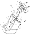
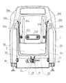
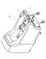
図1は、浴槽1内に車椅子3を挿入する前の状態の入浴装置22の外観を示す全体斜視図、図2は、浴槽1を開口部2方向から見た正面図である。図3は、浴槽1内に車椅子3を挿入した後の入浴装置22の外観を示す全体斜視図である。入浴装置22は、一側方に開口部2が形成された浴槽1と入浴者を載せる車椅子3とから構成される。
Embodiment 1 of the present invention will be described below with reference to FIGS.
FIG. 1 is an overall perspective view showing the external appearance of the bathing apparatus 22 before the wheelchair 3 is inserted into the bathtub 1, and FIG. 2 is a front view of the bathtub 1 as viewed from the direction of the opening 2. FIG. 3 is an overall perspective view showing an appearance of the bathing device 22 after the wheelchair 3 is inserted into the bathtub 1. The bathing apparatus 22 includes a bathtub 1 having an opening 2 formed on one side and a wheelchair 3 on which a bather is placed.

浴槽1には貯湯槽13が一体的に形成される。前記開口部2は、浴槽1の左右側壁1a・1bの内側面に開口部2側から浴槽1の奥側方向に向かって傾斜状に形成された左右内側壁1aa・1bbと底壁1cとで構成される接合面53を有し、該接合面53には後述する車椅子3の背凭れ部4に形成される左・右・下平坦面64a・64b・64cが当接可能となっている。尚、接合面53の周縁には、接合面53に沿って接合面53と背凭れ部4との水密状態を維持する為のシール材23が貼着される。尚、シール材23は、車椅子3の背凭れ部4の左・右・下平坦面64a・64b・64cの周縁に貼着してもよい。   A hot water tank 13 is integrally formed in the bathtub 1. The opening 2 is composed of left and right inner side walls 1aa and 1bb and a bottom wall 1c formed on the inner side surfaces of the left and right side walls 1a and 1b of the bathtub 1 so as to be inclined from the opening 2 side toward the back side of the bathtub 1. The joint surface 53 includes a left, right, and lower flat surfaces 64a, 64b, and 64c formed on the backrest portion 4 of the wheelchair 3 to be described later. A sealing material 23 is attached to the periphery of the joint surface 53 along the joint surface 53 to maintain a watertight state between the joint surface 53 and the backrest portion 4. The seal member 23 may be attached to the peripheral edges of the left, right, and lower flat surfaces 64a, 64b, and 64c of the backrest portion 4 of the wheelchair 3.

又、浴槽1の底壁1cの内側には、開口部2と反対側位置に段部54が形成される。段部54を形成することにより浴槽1の容積を減少させることができ、貯湯槽13から浴槽1へ移送する湯水の省湯量化が図れる。
図2中、56a及び56bは入浴者の両肩に向かって浴湯を噴出する肩掛けシャワーノズル、57a乃至57dは浴槽1内に向かって噴流を吐出する噴流ノズルである。
A stepped portion 54 is formed on the inner side of the bottom wall 1 c of the bathtub 1 at a position opposite to the opening 2. By forming the stepped portion 54, the volume of the bathtub 1 can be reduced, and the amount of hot water transferred from the hot water storage tank 13 to the bathtub 1 can be reduced.
In FIG. 2, 56 a and 56 b are shoulder shower nozzles that spray bath water toward both shoulders of the bather, and 57 a to 57 d are jet nozzles that discharge a jet toward the inside of the bathtub 1.

図4は、入浴装置22の配管系統及び電気的信号の流れの一部を模式的に示す図である。貯湯槽13の吸入口33と浴槽1の給湯口35とはポンプ24を介して給湯配管25にて連通接続される。吸入口33とポンプ24の吸込口側を接続する給湯配管25aにモーターバルブ34aが配設され、ポンプ24の吐出口側と給湯口35とを接続する給湯配管25bにモーターバルブ34bが配設される。   FIG. 4 is a diagram schematically showing a part of the piping system of the bathing apparatus 22 and the flow of electrical signals. The suction port 33 of the hot water tank 13 and the hot water supply port 35 of the bathtub 1 are connected to each other via a pump 24 through a hot water supply pipe 25. A motor valve 34a is disposed on the hot water supply pipe 25a that connects the suction port 33 and the suction port side of the pump 24, and a motor valve 34b is disposed on the hot water supply pipe 25b that connects the discharge port side of the pump 24 and the hot water supply port 35. The

モーターバルブ34aの下流側の給湯配管25aから給排湯配管36が分岐して設けられ、給排湯配管36は中途位置において分岐し浴槽1の給排湯口37に接続される。給排湯配管36にはモーターバルブ34c及び排湯用のモーターバルブ34dが配設される。モーターバルブ34bの上流側の給湯配管25bから排湯配管38が分岐して設けられ、排湯配管38に排湯用のモーターバルブ34eが設けられる。尚、貯湯槽13には、湯水供給源から供給される湯水を貯湯槽13へ至らせる図示しない配管が接続されている。   A hot and cold hot water supply pipe 36 is branched from the hot water supply pipe 25 a on the downstream side of the motor valve 34 a, and the hot and cold hot water supply pipe 36 is branched at an intermediate position and connected to the hot and cold hot water outlet 37 of the bathtub 1. A motor valve 34c and a motor valve 34d for draining hot water are disposed in the hot water supply / discharge pipe 36. A hot water discharge pipe 38 is branched from the hot water supply pipe 25b upstream of the motor valve 34b, and a hot water discharge motor valve 34e is provided in the hot water discharge pipe 38. The hot water storage tank 13 is connected to a pipe (not shown) for bringing hot water supplied from a hot water supply source to the hot water storage tank 13.

貯湯槽13の側壁内側の下方・上方位置にそれぞれ二基の水位センサ(=具体的には、静電容量型近接センサ)16a・16bが固着される。水位センサ16a・16bはそれぞれ貯湯槽13内の下限水位・上限水位を検出する為のものである。   Two water level sensors (= specifically, capacitive proximity sensors) 16a and 16b are fixed to the lower and upper positions inside the side wall of the hot water tank 13, respectively. The water level sensors 16a and 16b are for detecting a lower limit water level and an upper limit water level in the hot water tank 13, respectively.

浴槽1内部には、6基の水位センサ17a・17b・17c・17d・17e・17f(具体的には、静電容量型近接センサ)が固着される。前記6基の水位センサ17群は、床面52を基準面として水位センサ17a<17b<17c<17d<17e<17fの高さ位置の順序で固着されている。水位センサ17aは浴槽1内の下限水位を検出し、水位センサ17fは浴槽1内の上限水位を検出するためのものである。水位センサ17bはポンプ24の作動を許容する浴槽1内の水位を検出するためのものである。   Six water level sensors 17a, 17b, 17c, 17d, 17e, and 17f (specifically, capacitive proximity sensors) are fixed inside the bathtub 1. The six water level sensors 17 are fixed in the order of the height positions of the water level sensors 17a <17b <17c <17d <17e <17f with the floor 52 as a reference plane. The water level sensor 17a detects the lower limit water level in the bathtub 1, and the water level sensor 17f detects the upper limit water level in the bathtub 1. The water level sensor 17b is for detecting the water level in the bathtub 1 that allows the pump 24 to operate.

水位センサ17c・17d・17eはそれぞれ浴槽1内の水位を「低」・「中」・「高」レベルとして検出するものである。   The water level sensors 17c, 17d, and 17e detect the water level in the bathtub 1 as “low”, “medium”, and “high” levels, respectively.

入浴装置22に具備される制御部14は、前記水位センサ16群からの信号を適宜得て、貯湯槽13への貯湯作動を制御し、又、前記水位センサ16・17群からの信号を得て前記ポンプ24のON/OFF及び前記モーターバルブ34群の開閉を制御し、貯湯槽13から浴槽1への湯水の移送作動及び浴槽1内の湯水の排水作動等を制御する。更に、制御部14は、後述する浴槽1の左右側壁1a・1bと車椅子3の背凭れ部4の左右上部位置とを固定する第一の固定手段5の作動・非作動状態に係る信号、浴槽1及び貯湯槽13に固着される水位センサ16・17群からの信号を得て、浴槽1の底壁1cと車椅子3の背凭れ部4の下部とを固定する第二の固定手段6の作動を制御する。   The controller 14 provided in the bathing device 22 appropriately obtains a signal from the water level sensor 16 group, controls hot water storage operation to the hot water tank 13, and obtains a signal from the water level sensor 16/17 group. Thus, ON / OFF of the pump 24 and opening / closing of the motor valve 34 group are controlled, and the transfer operation of hot water from the hot water storage tank 13 to the bathtub 1 and the discharge operation of hot water in the bathtub 1 are controlled. Furthermore, the control part 14 is a signal which concerns on the action | operation / non-operation state of the 1st fixing means 5 which fixes the left-right side wall 1a * 1b of the bathtub 1 mentioned later, and the left-right upper part position of the backrest part 4 of the wheelchair 3. 1 and the operation of the 2nd fixing means 6 which acquires the signal from the water level sensors 16 and 17 group fixed to the hot water storage tank 13, and fixes the bottom wall 1c of the bathtub 1 and the lower part of the backrest part 4 of the wheelchair 3 To control.

図5は車椅子3の下肢支持部29を下降させた状態を示す右側面図、図6は車椅子3の下肢支持部29を上昇させた状態を示す右側面図、図7は車椅子3の下肢支持部29を上昇させた状態を示す平面図である。
車椅子3は、キャスターを有する平面視コ字形状の台車部26の台車フレーム70に右斜め上方向に略50°の角度に固設された背凭れ部4と、該背凭れ部4に固設された座席部27と、該座席部27の左右両側位置に設けられ手動で回動可能な左・右回動腕28a・28bと、該左・右回動腕28a・28bの先端部に左・右回動腕28a・28bに対して起倒可能に軸着され入浴者の下肢を支持する下肢支持部29とからなる。
5 is a right side view showing a state where the lower limb support portion 29 of the wheelchair 3 is lowered, FIG. 6 is a right side view showing a state where the lower limb support portion 29 of the wheelchair 3 is raised, and FIG. It is a top view which shows the state which raised the part 29. FIG.
The wheelchair 3 has a backrest portion 4 fixed to a bogie frame 70 of a U-shaped carriage portion 26 having a caster at an angle of approximately 50 ° diagonally right upward, and is fixed to the backrest portion 4. A seat portion 27, left and right turning arms 28a and 28b which are provided at both left and right positions of the seat portion 27 and can be turned manually, and left at the front ends of the left and right turning arms 28a and 28b. A lower limb support portion 29 that is pivotally attached to the right rotating arms 28a and 28b and supports the lower limb of the bather.

前記背凭れ部4は、FRP製の表側部材65と裏側部材71とが接合されて形成される。背凭れ部3の表側部材65には、中央部に入浴者の背中部分及び頭部分が載置される載置部42が隆起状に一体成形され、表側部材65の左右側部及び下部には浴槽1の開口部2に形成される接合面53と密接可能に平坦面64が形成される。前記平坦面64は、左平坦面64aと右平坦面64bと下平坦面64cとから構成される。   The backrest part 4 is formed by joining a front side member 65 and a back side member 71 made of FRP. On the front side member 65 of the backrest portion 3, a mounting portion 42 on which the bather's back portion and head portion are placed in the central portion is integrally formed in a raised shape, and on the left and right side portions and the lower portion of the front side member 65 A flat surface 64 is formed so as to be in close contact with the joint surface 53 formed in the opening 2 of the bathtub 1. The flat surface 64 includes a left flat surface 64a, a right flat surface 64b, and a lower flat surface 64c.

前記座席部27は、背凭れ部4の表側面左右位置に固着された座席支持枠30に被覆部材31が螺着されてなる。左右の座席支持枠30に、板状部材32が被覆部材31面に対して垂直方向に取着され、前記板状部材31に左・右回動腕28a・28bの基端部が回動自在に軸着される。回動腕28は板状部材31に設けられる図示しない係止固定手段を介して所定の上昇位置Dにて固定可能とされる(図6参照)。
下肢支持部29は下肢支持枠44に被覆部材45が螺着されてなり、下肢支持枠44の基端部は回動腕28の内側先端部に軸着されている。下肢支持枠44の先端部には脚裏当て46が下肢支持枠44に対して左斜め上方向に略45°の角度にて螺着される。
The seat portion 27 is formed by screwing a covering member 31 to a seat support frame 30 fixed to the left and right positions of the front side surface of the backrest portion 4. A plate-like member 32 is attached to the left and right seat support frames 30 in a direction perpendicular to the surface of the covering member 31, and the base end portions of the left and right turning arms 28 a and 28 b are freely turnable on the plate-like member 31. Attached to. The rotating arm 28 can be fixed at a predetermined raised position D via a locking fixing means (not shown) provided on the plate-like member 31 (see FIG. 6).
The lower limb support portion 29 is formed by screwing a covering member 45 to the lower limb support frame 44, and the base end portion of the lower limb support frame 44 is pivotally attached to the inner distal end portion of the rotating arm 28. A leg backing 46 is screwed to the distal end portion of the lower limb support frame 44 at an angle of approximately 45 ° obliquely upward to the left with respect to the lower limb support frame 44.

図5中、41は、板状部材32に覆設される保護カバー、43は背凭れ部4と座面支持枠30とに固着された把手、49は座席部27に着座した入浴者の上肢を背凭れ部4に固定する上肢固定ベルトである。   In FIG. 5, reference numeral 41 denotes a protective cover that covers the plate-like member 32, 43 denotes a handle fixed to the backrest portion 4 and the seating surface support frame 30, and 49 denotes an upper limb of a bather sitting on the seat portion 27. It is an upper limb fixing belt for fixing the to the backrest part 4.

図7に示すように背凭れ部4の左右側面の上方位置には左右方向(背凭れ部4の横幅方向)に向かってそれぞれ進退可能に左・右ロックピン7a・7bが突設される。背凭れ部4の裏側位置に、前記ロックピン7の進退移動を操作する操作手段12としての操作レバー20が設けられる。   As shown in FIG. 7, left and right lock pins 7a and 7b project from the left and right side surfaces of the backrest portion 4 so as to be able to advance and retreat in the left-right direction (lateral width direction of the backrest portion 4). An operation lever 20 is provided at the back side of the backrest portion 4 as an operation means 12 for operating the lock pin 7 to move forward and backward.

図8に、操作手段12に係る内部機構を表わした部分斜視図を示す。操作レバー20は、平面視コ字形状の部材20aの開口部側の先端位置に入浴者が把持する棒状の部材20bが横架されてなる。前記部材20aは、背凭れ部4の表側部材65の左右方向に亘って横架される背凭れフレーム21aの中央部に取着されるガイド部材59に前後移動可能に挿入され、部材20aはガイド部材59にバネ60で連結され、該バネ60により常時表側部材65方向に付勢されている。   FIG. 8 is a partial perspective view showing an internal mechanism related to the operation means 12. The operation lever 20 includes a rod-shaped member 20b that is held by a bather at a tip position on the opening side of the U-shaped member 20a in plan view. The member 20a is inserted in a guide member 59 attached to the center portion of the backrest frame 21a that is laid across the left-right direction of the front side member 65 of the backrest portion 4 so as to be movable back and forth. The member 59 is connected by a spring 60 and is always biased toward the front side member 65 by the spring 60.

左・右ロックピン7a・7bは、それぞれ表側部材65の左右上方位置に設けられる略三角形形状の背凭れフレーム21bに螺着されたパイプ材58・58に嵌通される。前記部材20aの左右側方位置に背凭れフレーム21aから下方方向に向かってピン61・61が螺着され、該ピン61・61に略V字形状のリンク片62・62の基端部が回動可能に取着されている。各リンク片62のロックピン7側の一方辺62aとロックピン7の基端部とがワイヤー18にて連結されている。   The left and right lock pins 7a and 7b are fitted into pipe members 58 and 58 that are screwed to a substantially triangular backrest frame 21b provided at the upper left and right positions of the front side member 65, respectively. Pins 61 and 61 are screwed downward from the backrest frame 21a to the left and right side positions of the member 20a, and the base ends of the substantially V-shaped link pieces 62 and 62 are rotated around the pins 61 and 61. It is attached movably. One side 62 a of each link piece 62 on the lock pin 7 side and the base end portion of the lock pin 7 are connected by a wire 18.

左・右ロックピン7a・7bはそれぞれ背凭れフレーム21aに取着されたバネ19・バネ(図示省略)によって外側方向に常時付勢され、各リンク片62の一方辺62aは前記バネ19によって外側方向に付勢されている。各リンク片62の他方辺62bは、部材20aの左右端位置に上方方向に向かって突出形成された突状部63に当接している。   The left and right lock pins 7a and 7b are always urged outwardly by springs 19 and springs (not shown) attached to the backrest frame 21a, respectively, and one side 62a of each link piece 62 is outside by the spring 19. Is biased in the direction. The other side 62b of each link piece 62 is in contact with a protruding portion 63 that is formed to protrude upward at the left and right end positions of the member 20a.

介助者が操作レバー20を把持し手前方向に引き出すと、操作レバー20はバネ60の付勢力に抗して背凭れ部4の表側部材65と離間する方向に移動すると同時に、リンク片62の他方辺62bが突起部63により押されリンク片62が背凭れ部4の中央方向に回転する。これにより、左・右ロックピン7a・7bはバネ19の付勢力に抗してパイプ材58の内部方向に退入する。介助者が操作レバー20を離すと、操作レバー20はバネ60により表側部材65に接近する方向に付勢移動すると共に、各リンク片62がバネ19に引っ張られ外側方向に逆回転すると共にロックピン7がパイプ材58の外側方向に進出する。   When the assistant grips the operation lever 20 and pulls it out in the forward direction, the operation lever 20 moves in a direction away from the front side member 65 of the backrest 4 against the biasing force of the spring 60, and at the same time, the other of the link pieces 62 The side 62b is pushed by the protrusion 63, and the link piece 62 rotates in the center direction of the backrest 4. As a result, the left and right lock pins 7 a and 7 b retreat in the inner direction of the pipe member 58 against the biasing force of the spring 19. When the assistant releases the operation lever 20, the operation lever 20 is urged and moved in the direction approaching the front member 65 by the spring 60, and each link piece 62 is pulled by the spring 19 to reversely rotate outward and the lock pin. 7 advances toward the outside of the pipe material 58.

次に、車椅子3に設けられる背凭れ部4の表側面に対するロックピン7の位置を調整する第一の調整手段47について述べる。図9は、図7におけるA−A線方向の部分断面図である。ロックピン7が挿通されるパイプ材58の基端側には板状部58aと、該板状部58aの一端から延出される棒状部58bとが一体的に形成される。前記板状部58aには二箇所長孔66が開設される。   Next, the first adjusting means 47 for adjusting the position of the lock pin 7 with respect to the front side surface of the backrest portion 4 provided in the wheelchair 3 will be described. FIG. 9 is a partial cross-sectional view taken along line AA in FIG. A plate-like portion 58a and a rod-like portion 58b extending from one end of the plate-like portion 58a are integrally formed on the proximal end side of the pipe member 58 through which the lock pin 7 is inserted. Two long slots 66 are formed in the plate-like portion 58a.

パイプ材58の板状部58a上側から前記二箇所の長孔66にそれぞれ止着具67(ボルト)を挿入し、背凭れフレーム21bにパイプ材58を止着固定する。パイプ材58の棒状部58bの先端側は、パイプ材58の位置調整を妨げないよう背凭れフレーム21bに掛止される。
従って、ロックピン7の位置を、背凭れ部4の表側面(表側部材65)に対して前後方向(図9中の矢印方向)に調整する時は、2箇所の止着具67を緩め、パイプ材58を背凭れフレーム21b面に沿って移動させロックピン7の位置決めを行った後、止着具67を締め、パイプ材58を背凭れフレーム21bに固定する。
Fasteners 67 (bolts) are respectively inserted into the two long holes 66 from above the plate-like portion 58a of the pipe member 58, and the pipe member 58 is fixedly fixed to the backrest frame 21b. The tip end side of the rod-shaped portion 58b of the pipe material 58 is hooked on the backrest frame 21b so as not to hinder the position adjustment of the pipe material 58.
Therefore, when adjusting the position of the lock pin 7 in the front-rear direction (the arrow direction in FIG. 9) with respect to the front side surface (front side member 65) of the backrest portion 4, two fastening devices 67 are loosened, After the pipe member 58 is moved along the backrest frame 21b and the lock pin 7 is positioned, the fastening member 67 is tightened to fix the pipe member 58 to the backrest frame 21b.

浴槽1と、車椅子3の背凭れ部4との固定は、以下の二つの手段により行う。一つは、浴槽1の左右側壁1a・1bと車椅子3の背凭れ部4の左右側上部を固定する第一の固定手段5であり、もう一つは浴槽1の底壁1cと車椅子3の背凭れ部4の下部を固定する第二の固定手段6である。   The bathtub 1 and the backrest 4 of the wheelchair 3 are fixed by the following two means. One is first fixing means 5 for fixing the left and right side walls 1a and 1b of the bathtub 1 and the left and right upper parts of the backrest part 4 of the wheelchair 3, and the other is the bottom wall 1c of the bathtub 1 and the wheelchair 3. This is a second fixing means 6 for fixing the lower part of the backrest part 4.

第一の固定手段5は、車椅子側に設けられる前記左・右ロックピン7a・7bと、浴槽側に設けられる左孔(図示省略)・右孔8aとから構成される。
浴槽1の接合面53より前方方向に突出して設けられた左右側壁1a・1bの内側上方位置にそれぞれ略L字形状の左・右補強部材55a・55bが取着される(図2参照)。図10に、補強部材55bの部分斜視図を示す。図10に示すように、右補強部材55bに左ロックピン7aが嵌入する右孔8aが貫設される。尚、図示を省略するが、左補強部材55aには右ロックピン7bが嵌入する左孔が貫設される。
The first fixing means 5 includes the left and right lock pins 7a and 7b provided on the wheelchair side, and a left hole (not shown) and right hole 8a provided on the bathtub side.
The substantially L-shaped left and right reinforcing members 55a and 55b are attached to the upper positions on the inner sides of the left and right side walls 1a and 1b that protrude forward from the joint surface 53 of the bathtub 1 (see FIG. 2). FIG. 10 is a partial perspective view of the reinforcing member 55b. As shown in FIG. 10, a right hole 8a into which the left lock pin 7a is fitted is provided through the right reinforcing member 55b. Although not shown, the left reinforcing member 55a is provided with a left hole into which the right lock pin 7b is fitted.

前記左・右補強部材55a・55bは、浴槽1の左右側壁1a・1bに対して前後方向に移動して再取着可能になされており、従って、ロックピン7を浴槽1の孔8に嵌入した際に、浴槽1の開口部2の接合面53と背凭れ部4の左・右平坦面64a・64bの上部との間に僅かな空隙が生じてしまった場合にも、孔8の位置を微調整する、即ち、孔8の位置を背凭れ部4の表側面から離間する方向(浴槽の奥側方向)に移動させることにより、接合面53と背凭れ部4の左・右平坦面64a・64bの上部とを当接させ容易に閉塞状態となすことができる。   The left and right reinforcing members 55a and 55b are movable in the front-rear direction with respect to the left and right side walls 1a and 1b of the bathtub 1 so that they can be reattached. Therefore, the lock pin 7 is fitted into the hole 8 of the bathtub 1 The position of the hole 8 also when a slight gap is generated between the joint surface 53 of the opening 2 of the bathtub 1 and the upper portions of the left and right flat surfaces 64a and 64b of the backrest 4 Is adjusted, that is, by moving the position of the hole 8 in a direction away from the front side surface of the backrest portion 4 (backward direction of the bathtub), the left and right flat surfaces of the joint surface 53 and the backrest portion 4 The upper part of 64a * 64b can be contact | abutted and it can be set as a closed state easily.

図10に示されるように補強部材55bに貫設される孔8bは、浴槽1の右内側壁1bbの傾斜角度と略同一角度方向に伸長形成される長孔である。従って、浴槽1と車椅子3の固定の際に、床面52の勾配等により浴槽1と車椅子3の高さ位置に多少ずれが生じたとしても、開口部2の接合面53と背凭れ部4の平坦面64との面間距離は常に一定に維持される。   As shown in FIG. 10, the hole 8 b penetrating the reinforcing member 55 b is a long hole that extends in the direction substantially the same as the inclination angle of the right inner wall 1 bb of the bathtub 1. Therefore, when the bathtub 1 and the wheelchair 3 are fixed, even if the height of the bathtub 1 and the wheelchair 3 is slightly shifted due to the gradient of the floor 52 or the like, the joint surface 53 of the opening 2 and the backrest 4 The distance between the flat surface 64 and the flat surface 64 is always kept constant.

左孔・右孔8a位置に対応する左・右補強部材55a・55bの所定位置にはそれぞれリミットスイッチ15が取着される。リミットスイッチ15から出力される電気的信号は制御部14に送信され、リミットスイッチ15からの信号を得た制御部14により後述する第二の固定手段6による浴槽1と車椅子3との固定作動が許容されるよう電気的配線が施されている。即ち、左・右ロックピン7a・7bがそれぞれ左孔・右孔8aへ嵌入作動することにより、リミットスイッチ15がONとなり、リミットスイッチ15のON信号が制御部14に送信され、制御部14により第二の固定手段6の固定作動が許容される。   Limit switches 15 are attached to predetermined positions of the left and right reinforcing members 55a and 55b corresponding to the positions of the left hole and the right hole 8a, respectively. The electrical signal output from the limit switch 15 is transmitted to the control unit 14, and the controller 14 that has obtained the signal from the limit switch 15 performs the fixing operation of the bathtub 1 and the wheelchair 3 by the second fixing means 6 described later. Electrical wiring is provided to allow. That is, when the left and right lock pins 7a and 7b are inserted into the left and right holes 8a, respectively, the limit switch 15 is turned on, and an ON signal of the limit switch 15 is transmitted to the control unit 14, and the control unit 14 The fixing operation of the second fixing means 6 is allowed.

図11は、入浴装置22の第二の固定手段6を示す部分斜視図である。浴槽1の底壁1cの下方位置には、底壁1cと浴槽1内に挿入された車椅子3の背凭れ部4の下部とを固定する第二の固定手段6が配置される。
第二の固定手段6は、底壁1cの下方外面に固着された電動アクチュエーター9と、該電動アクチュエーター9の伸縮自在なロッド10の先端部と底壁1cの端面とに軸着される押圧片11と、車椅子3の背凭れ部4の下端の背凭れフレーム21cに螺着され押圧片11の押圧を受け止める受止部材50とから構成される。従って、電動アクチュエーター9のロッド10の伸長作動が開始されると、押圧片11の先端部11aが左回転し受止部材50に当接する。更に、ロッド10の伸長作動が行われると、押圧片11により受止部材50が押圧され、浴槽1の底壁1cに車椅子3の背凭れ部4の下部が押圧固定される。上述した第一の固定手段5と第二の固定手段6とにより浴槽1の開口部2が車椅子3の背凭れ部4で閉塞されることになる。ロッド10を収縮作動させれば、先端部11aが逆回転し受止部材50から離間し、浴槽1の底壁1cと車椅子3の背凭れ部4の下部との固定が解除される。
FIG. 11 is a partial perspective view showing the second fixing means 6 of the bathing device 22. A second fixing means 6 that fixes the bottom wall 1 c and the lower portion of the backrest portion 4 of the wheelchair 3 inserted into the bathtub 1 is disposed at a position below the bottom wall 1 c of the bathtub 1.
The second fixing means 6 includes an electric actuator 9 fixed to the lower outer surface of the bottom wall 1c, and a pressing piece pivotally attached to the distal end portion of the telescopic rod 10 of the electric actuator 9 and the end surface of the bottom wall 1c. 11 and a receiving member 50 that is screwed to the backrest frame 21c at the lower end of the backrest portion 4 of the wheelchair 3 and receives the pressing force of the pressing piece 11. Therefore, when the extension operation of the rod 10 of the electric actuator 9 is started, the distal end portion 11a of the pressing piece 11 rotates counterclockwise and comes into contact with the receiving member 50. When the rod 10 is further extended, the receiving member 50 is pressed by the pressing piece 11, and the lower portion of the backrest portion 4 of the wheelchair 3 is pressed and fixed to the bottom wall 1 c of the bathtub 1. The opening 2 of the bathtub 1 is closed by the backrest 4 of the wheelchair 3 by the first fixing means 5 and the second fixing means 6 described above. When the rod 10 is contracted, the distal end portion 11a rotates in the reverse direction and is separated from the receiving member 50, and the fixation between the bottom wall 1c of the bathtub 1 and the lower portion of the backrest portion 4 of the wheelchair 3 is released.

ロッド10を伸長作動させ、押圧片11により受止部材50を押圧し、浴槽1の底壁1cに車椅子3の背凭れ部4の下部を押圧固定する際に、ロッド10の伸長量が小さく押圧片11により受止部材50を十分に押圧できない場合には、ロッド10の伸長量を増大させる調整が可能となっている。又、前記の場合とは逆に、ロッド10の伸長量が大き過ぎる場合には、ロッド10の伸長量を減少させる調整も可能となっている。ロッド10の伸長量の適宜な増減調整により、一台の車椅子3を、複数個配設される浴槽1のいずれにも容易に適用可能とすることができ、好都合である。   When the rod 10 is extended, the receiving member 50 is pressed by the pressing piece 11, and the lower portion of the backrest 4 of the wheelchair 3 is pressed and fixed to the bottom wall 1 c of the bathtub 1, the amount of extension of the rod 10 is small. When the receiving member 50 cannot be sufficiently pressed by the piece 11, an adjustment to increase the extension amount of the rod 10 is possible. Contrary to the case described above, when the amount of extension of the rod 10 is too large, adjustment to decrease the amount of extension of the rod 10 is also possible. Conveniently, a single wheelchair 3 can be easily applied to any of a plurality of bathtubs 1 by adjusting the amount of extension of the rod 10 appropriately.

上述した電動アクチュエーター9のロッド10の伸長作動は、ロックピン7が孔8へ嵌入した状態であって、貯湯槽13内の水位が水位センサ16bの高さ位置以上に至っている状態(満水状態)の時、即ち、リミットスイッチ15のON信号及び水位センサ16bのON信号が制御部14へ入力されている時のみ、制御部14により許容される。   The extension operation of the rod 10 of the electric actuator 9 described above is a state in which the lock pin 7 is fitted into the hole 8, and the water level in the hot water storage tank 13 reaches or exceeds the height position of the water level sensor 16b (full state). In other words, only when the ON signal of the limit switch 15 and the ON signal of the water level sensor 16 b are input to the control unit 14, the control unit 14 allows it.

制御部14は電動アクチュエーター9の伸長作動中、常時電動アクチュエーター9への駆動電流値を検出している。ここで、電動アクチュエーター9のロッド10が伸長され、所定の伸長位置に至ると電動アクチュエーター9に内蔵された図示しないリミットスイッチがONとなり、電動アクチュエーター9へは駆動電流が流れなくなる。制御部14は前記状態を検知し、第二の固定手段6による固定が完了された状態と判断し、貯湯槽13から浴槽1への湯移送制御を可能にする。尚、図示を省略するが、ロッド10の伸長作動の停止を、ロッド10の伸長作動により浴槽1の底壁1cに取着したリミットスイッチが押下されることで行うようにしてもよい。   The controller 14 constantly detects the drive current value to the electric actuator 9 during the extension operation of the electric actuator 9. Here, when the rod 10 of the electric actuator 9 is extended and reaches a predetermined extended position, a limit switch (not shown) built in the electric actuator 9 is turned ON, and the drive current does not flow to the electric actuator 9. The control unit 14 detects the state, determines that the fixing by the second fixing means 6 is completed, and enables hot water transfer control from the hot water storage tank 13 to the bathtub 1. Although not shown, the extension operation of the rod 10 may be stopped by pressing a limit switch attached to the bottom wall 1c of the bathtub 1 by the extension operation of the rod 10.

浴槽1内の湯水排出作動により浴槽1内の水位が減少し水位センサ17aの高さ位置未満になると、水位センサ17aのOFF信号が制御部14に入力され、制御部14により電動アクチュエーター9のロッド10の収縮作動が許容される。ロッド10が所定の収縮位置にまで達すると、電動アクチュエーター9の作動が停止される。   When the water level in the bathtub 1 decreases due to the hot water discharge operation in the bathtub 1 and becomes less than the height position of the water level sensor 17a, an OFF signal of the water level sensor 17a is input to the control unit 14, and the control unit 14 inputs the rod of the electric actuator 9 Ten contraction operations are allowed. When the rod 10 reaches a predetermined contracted position, the operation of the electric actuator 9 is stopped.

又、車椅子3には、背凭れ部4の表側面に対する受止部材50の位置を調整する第二の調整手段48が設けられる。図12は、図6におけるB−B線方向の部分断面図である。受止部材50は、その両端を止着具68で背凭れフレーム21cに止着される。止着具68は、具体的には背凭れフレーム21cに取着されたボルトと、ナットとからなる。   The wheelchair 3 is provided with second adjusting means 48 for adjusting the position of the receiving member 50 with respect to the front side surface of the backrest 4. 12 is a partial cross-sectional view taken along the line BB in FIG. The both ends of the receiving member 50 are fixed to the backrest frame 21c by a fixing tool 68. Specifically, the fastening tool 68 includes a bolt and a nut attached to the backrest frame 21c.

背凭れ部4の表側面(表側部材65)に対する受止部材50の位置を調整する際は、ナットを緩め、背凭れフレーム21cに対する受止部材50の位置を適宜調整した後、ナットを締め前記位置にて受止部材50を固定する。背凭れフレーム21cと受止部材50との距離を一定に保持する為、受止部材50の二乃至三箇所位置を押しボルト69で背凭れフレーム21c方向に押圧している。尚、図12は受止部材50の二箇所位置を押しボルト69で押圧した状態を示した図である。   When adjusting the position of the receiving member 50 with respect to the front side surface (front side member 65) of the backrest portion 4, the nut is loosened, the position of the receiving member 50 with respect to the backrest frame 21c is adjusted as appropriate, and then the nut is tightened. The receiving member 50 is fixed at the position. In order to keep the distance between the backrest frame 21 c and the receiving member 50 constant, two or three positions of the receiving member 50 are pressed in the direction of the backrest frame 21 c by the push bolts 69. FIG. 12 is a view showing a state where the two positions of the receiving member 50 are pressed by the push bolt 69.

入浴装置22を用いて、入浴者を入浴させる場合、先ず貯湯槽13へ湯水を所定量貯湯する。次に、介助者は、図示を省略するが下肢支持部29を回動腕28に対して手動にて倒伏作動させ入浴者を他機器から車椅子3の座席部27へ移乗させる。下肢支持部29を起立作動させ、入浴者の下肢を下肢支持部29上に載置する。入浴者の上肢を上肢固定ベルト49にて背凭れ部4に固定する。下降位置C(図5)になっている下肢支持部29を手動にて持ち上げ、下肢支持部29を所定の上昇位置D(図6)にて固定する。   When bathing a bather using the bathing device 22, first, a predetermined amount of hot water is stored in the hot water storage tank 13. Next, although not shown, the assistant manually operates the lower limb support portion 29 with respect to the rotary arm 28 to move the bather from another device to the seat portion 27 of the wheelchair 3. The lower limb support part 29 is erected and the bather's lower limb is placed on the lower limb support part 29. The upper limb of the bather is fixed to the backrest 4 by the upper limb fixing belt 49. The lower limb support part 29 in the lowered position C (FIG. 5) is manually lifted, and the lower limb support part 29 is fixed at a predetermined raised position D (FIG. 6).

この状態で介助者は車椅子3の背凭れ部4の裏側位置に設けられた押しハンドル39を操作し、車椅子3を床面52上を走行させる。車椅子3を浴槽1の開口部2付近に配置し、開口部2方向に延出し左右側壁1a・1bに沿って平行に取着されたガイドレール40・40に台車フレーム70を当接させながら、車椅子3を開口部2側から浴槽1内へ進入させる。この時、台車部26は、底壁1cの下方外部に位置し、座席部27及び下肢支持部29が浴槽1内に位置する。尚、車椅子3の下肢支持部29は上昇位置に固定されているので、浴槽1の内方に挿入された場合にも底壁1cに形成された段部54に衝突することはない。   In this state, the assistant operates the push handle 39 provided at the back side position of the backrest portion 4 of the wheelchair 3 to cause the wheelchair 3 to travel on the floor 52. While the wheelchair 3 is disposed near the opening 2 of the bathtub 1, and the carriage frame 70 is brought into contact with the guide rails 40 and 40 extending in the direction of the opening 2 and attached in parallel along the left and right side walls 1a and 1b, The wheelchair 3 is made to enter the bathtub 1 from the opening 2 side. At this time, the carriage part 26 is located outside the bottom wall 1 c, and the seat part 27 and the lower limb support part 29 are located in the bathtub 1. In addition, since the leg support part 29 of the wheelchair 3 is being fixed to the raising position, even if it inserts inward of the bathtub 1, it does not collide with the step part 54 formed in the bottom wall 1c.

車椅子3を浴槽1の内方所定位置にまで進入させると、ロックピン7が孔8に自動的に嵌入し、車椅子3の背凭れ部4の上部と浴槽1とが固定される。次に、電動アクチュエーター9のロッド10を伸長作動させ、押圧片11にて受止部材50を押圧すると、背凭れ部4の左平坦面64a・右平坦面64b・下平坦面64cがそれぞれ浴槽1の右内側壁1bb・左内側壁1aa・底壁1cに当接され、浴槽1の開口部2が車椅子3の背凭れ部4で閉塞される。
前記閉塞状態になした直後は、モーターバルブ34a・34d・34eが閉弁され、モーターバルブ34b・34cが開弁された状態となるよう制御部14にて制御されている。
When the wheelchair 3 is advanced to a predetermined position inside the bathtub 1, the lock pin 7 is automatically fitted into the hole 8, and the upper portion of the backrest portion 4 of the wheelchair 3 and the bathtub 1 are fixed. Next, when the rod 10 of the electric actuator 9 is extended and the receiving member 50 is pressed by the pressing piece 11, the left flat surface 64a, the right flat surface 64b, and the lower flat surface 64c of the backrest 4 are respectively in the bathtub 1. The right inner wall 1bb, the left inner wall 1aa, and the bottom wall 1c are in contact with each other, and the opening 2 of the bathtub 1 is closed by the backrest 4 of the wheelchair 3.
Immediately after the closed state, the motor valves 34a, 34d and 34e are closed, and the control unit 14 controls the motor valves 34b and 34c to be opened.

この時、介助者により操作パネル51面に装備された図示しない給湯スイッチが押下され制御部14が初期給湯開始の信号を受けると、制御部14によりモーターバルブ34aが開弁され、貯湯槽13内の湯水が給湯配管25及び給排湯配管36を経由して浴槽1内へ自然流入し移送される。水位センサ17bが浴槽1内に移送された湯の水位を検出するまで、ポンプ24は作動しない。   At this time, when a hot water switch (not shown) provided on the surface of the operation panel 51 is pressed by an assistant and the control unit 14 receives a signal for starting an initial hot water supply, the control unit 14 opens the motor valve 34a and the hot water tank 13 Of hot water naturally flows into the bathtub 1 through the hot water supply pipe 25 and the hot and cold water supply pipe 36 and is transferred. The pump 24 does not operate until the water level sensor 17b detects the water level of the hot water transferred into the bathtub 1.

水位センサ17bが湯水位を検出すると同時に、モーターバルブ34cが閉弁され、ポンプ24の作動が開始され、ポンプ24の作動により給湯配管25を経由して浴槽1内へ湯移送がなされる。介助者にて設定された水位(「低」・「中」・「高」レベル水位のいずれか)にまで浴槽1内の湯水が達すると制御部14によりモーターバルブ34aが閉弁され、モーターバルブ34cが開弁され、ポンプ24の作動が停止され、初期給湯が完了する。   At the same time that the water level sensor 17b detects the hot water level, the motor valve 34c is closed and the operation of the pump 24 is started, and hot water is transferred into the bathtub 1 through the hot water supply pipe 25 by the operation of the pump 24. When the hot water in the bathtub 1 reaches the water level set by the assistant (any one of the “low”, “medium”, and “high” level water levels), the controller 14 closes the motor valve 34a, and the motor valve 34c is opened, the operation of the pump 24 is stopped, and the initial hot water supply is completed.

入浴が完了し入浴者を退浴させる場合、浴槽1内の現在水位が水位センサ17bの高さ位置以上の時に、操作パネル51面に装備された図示しない浴槽排水スイッチが押下され浴槽排水の信号が制御部14に入力されると、制御部14によりモーターバルブ34bが閉弁され、モーターバルブ34eが開弁され、ポンプ24の作動が開始され、該ポンプ24の作動により浴槽1内の湯水は給排湯配管36から給湯配管25を経由して排湯配管38へと導かれた後、入浴装置22外へ強制排出される。   When bathing is completed and the bather is to be retreated, when the current water level in the bathtub 1 is equal to or higher than the height position of the water level sensor 17b, a bathtub drain switch (not shown) provided on the operation panel 51 is pressed and the bathtub drain signal is displayed. Is input to the control unit 14, the motor valve 34 b is closed by the control unit 14, the motor valve 34 e is opened, and the operation of the pump 24 is started. After being led from the hot water supply / pipe 36 to the hot water supply pipe 38 via the hot water supply pipe 25, it is forcibly discharged out of the bathing apparatus 22.

浴槽1内の現在水位が水位センサ17bの高さ位置未満になると、ポンプ24の作動が停止され、モーターバルブ34b・34dが開弁され、浴槽1内の湯水が給排湯口37から給排湯配管36を経由すると同時に給湯口35から排湯配管38を経由して入浴装置22外へ自然排出される。   When the current water level in the bathtub 1 becomes less than the height position of the water level sensor 17 b, the operation of the pump 24 is stopped, the motor valves 34 b and 34 d are opened, and hot water in the bathtub 1 is supplied and discharged from the supply and discharge hot water outlet 37. At the same time as passing through the pipe 36, it is naturally discharged from the hot water supply port 35 to the outside of the bath apparatus 22 via the hot water discharge pipe 38.

上述した浴槽1内の湯水排出作動により浴槽1内の水位が減少し水位センサ17aの高さ位置未満になると、ロッド10の収縮作動が許容されるので、介助者は、ロッド10を収縮させ、押圧片11による受止部材50の押圧固定を解除し、浴槽1の底壁1cと車椅子3の背凭れ部4の下部との固定を解除する。次に、車椅子3の操作レバー20を手前方向に引き、ロックピン7を孔8から抜脱し、浴槽1の左右側壁1a・1bと車椅子3の背凭れ部4の左右側上部との固定を解除し、車椅子3を浴槽1内から退出させる。   When the water level in the bathtub 1 decreases due to the hot water discharge operation in the bathtub 1 and becomes less than the height position of the water level sensor 17a, the contraction operation of the rod 10 is allowed, so the assistant contracts the rod 10, The pressing and fixing of the receiving member 50 by the pressing piece 11 is released, and the fixing of the bottom wall 1c of the bathtub 1 and the lower part of the backrest part 4 of the wheelchair 3 is released. Next, the operation lever 20 of the wheelchair 3 is pulled forward, the lock pin 7 is removed from the hole 8, and the fixation between the left and right side walls 1 a and 1 b of the bathtub 1 and the upper left and right sides of the backrest part 4 of the wheelchair 3 is released. Then, the wheelchair 3 is moved out of the bathtub 1.

介助者は、上昇位置Dにある下肢支持部29を、手動にて下降位置Cにまで下降させる。下肢支持部29を回動腕28に対して倒伏作動させ、上肢固定ベルト49を入浴者から解き、入浴者を車椅子3から他機器へ移乗し、入浴を完了する。   The caregiver manually lowers the lower limb support portion 29 at the raised position D to the lowered position C. The lower limb support portion 29 is inclined to the rotating arm 28, the upper limb fixing belt 49 is unwound from the bather, the bather is transferred from the wheelchair 3 to another device, and bathing is completed.

一槽の浴槽1に、複数台の車椅子3をローテーションさせながら複数の入浴者を順次交互に入浴させる場合には、事前に、前述した車椅子3に設けられる第一の調整手段47と第二の調整手段48を用いて、浴槽1の接合面53と車椅子3の背凭れ部4に形成される平坦面64とが閉塞状態となるよう適宜調整を施す。   In the case where a plurality of bathers are sequentially bathed sequentially while rotating a plurality of wheelchairs 3 in one tub 1, the first adjusting means 47 provided in the wheelchair 3 described above and the second adjuster 47 are provided in advance. Using the adjustment means 48, it adjusts suitably so that the joint surface 53 of the bathtub 1 and the flat surface 64 formed in the backrest part 4 of the wheelchair 3 may be in the obstruction | occlusion state.

又、一台の車椅子3を、浴室に複数個配設される浴槽1のうち未使用状態にある一槽に適用して使用する場合、浴槽1に設けられる孔8の位置調整とロッド10の伸長量調整を適宜行い、浴槽1の接合面53と背凭れ部4に形成される平坦面64とが適切な閉塞状態となるようにする。   In addition, when one wheelchair 3 is used by being applied to one unused tank among the bathtubs 1 arranged in the bathroom, the position adjustment of the holes 8 provided in the bathtub 1 and the rod 10 The extension amount is adjusted as appropriate so that the joint surface 53 of the bathtub 1 and the flat surface 64 formed on the backrest 4 are in an appropriate closed state.

尚、第一の調整手段47と第二の調整手段48、孔8の位置調整とロッド10の伸長量調整のどちらか一組だけの調整ではなく、例えば、第一の調整手段47とロッド10の伸長量調整のように両者を適宜組み合せ、最適な閉塞状態を実現するよう調整を行ってもよい。   Note that the first adjustment means 47 and the second adjustment means 48, the adjustment of the position of the hole 8, and the adjustment of the extension amount of the rod 10 are not limited to one set. For example, the first adjustment means 47 and the rod 10 are adjusted. Both may be combined as appropriate to adjust the amount of extension, and an adjustment may be made to achieve an optimal closed state.

本発明は、一側方に開口部が形成された浴槽と、貯湯槽とを有し、開口部から車椅子を浴槽内へ挿入し、開口部を車椅子で水密保持する入浴装置に適用できる。   INDUSTRIAL APPLICABILITY The present invention can be applied to a bathing apparatus that has a bathtub having an opening formed on one side and a hot water storage tank, inserts a wheelchair into the bathtub from the opening, and holds the opening watertight with the wheelchair.

本発明の浴槽内に車椅子を挿入する前状態の入浴装置の外観を示す全体斜視図である。It is a whole perspective view which shows the external appearance of the bathing apparatus of the state before inserting a wheelchair in the bathtub of this invention. 本発明の浴槽を開口部方向から見た正面図である。It is the front view which looked at the bathtub of this invention from the opening part direction. 本発明の浴槽内に車椅子を挿入した後状態の入浴装置の外観を示す全体斜視図である。It is a whole perspective view which shows the external appearance of the bathing apparatus of the state after inserting a wheelchair in the bathtub of this invention. 本発明の入浴装置の配管系統及び電気的信号の流れの一部を模式的に示す図である。It is a figure which shows typically a part of flow of the piping system of the bathing apparatus of this invention, and an electrical signal. 本発明の下肢支持部を下降させた状態の車椅子を示す右側面図である。It is a right view which shows the wheelchair of the state which lowered | hung the leg support part of this invention. 本発明の下肢支持部を上昇させた状態の車椅子を示す右側面図である。It is a right view which shows the wheelchair of the state which raised the leg support part of this invention. 本発明の下肢支持部を上昇させた状態の車椅子を示す平面図である。It is a top view which shows the wheelchair of the state which raised the leg support part of this invention. 本発明の操作手段に係る内部機構を示す部分斜視図である。It is a fragmentary perspective view which shows the internal mechanism which concerns on the operation means of this invention. 図7におけるA−A矢視断面図である。It is AA arrow sectional drawing in FIG. 本発明の浴槽に設けられる補強部材を示す部分斜視図である。It is a fragmentary perspective view which shows the reinforcement member provided in the bathtub of this invention. 本発明の入浴装置の第二の固定手段を示す部分斜視図である。It is a fragmentary perspective view which shows the 2nd fixing means of the bathing apparatus of this invention. 図6におけるB−B矢視断面図である。It is BB arrow sectional drawing in FIG.

符号の説明Explanation of symbols

1 浴槽
1a 左側壁
1b 右側壁
1c 底壁
2 開口部
3 車椅子
4 背凭れ部
5 第一の固定手段
6 第二の固定手段
7 ロックピン
8 孔
9 電動アクチュエーター
10 ロッド
11 押圧片
12 操作手段
13 貯湯槽
47 第一の調整手段
48 第二の調整手段
50 受止部材
DESCRIPTION OF SYMBOLS 1 Bathtub 1a Left side wall 1b Right side wall 1c Bottom wall 2 Opening part 3 Wheelchair 4 Backrest part 5 First fixing means 6 Second fixing means 7 Lock pin 8 Hole 9 Electric actuator 10 Rod 11 Pressing piece 12 Operating means 13 Hot water storage Tank 47 First adjusting means 48 Second adjusting means 50 Receiving member

Claims (9)

一側方に開口部2が形成された浴槽1と、貯湯槽13とを有し、開口部2から車椅子3を浴槽1内へ挿入し、開口部2を車椅子3で水密保持する入浴装置において、浴槽1の左右側壁1a・1bと車椅子3の背凭れ部4の左右側上部を固定する第一の固定手段5と、浴槽1の底壁1cと車椅子3の背凭れ部4の下部を固定する第二の固定手段6とを具備することを特徴とする入浴装置。   In the bathing apparatus which has the bathtub 1 in which the opening part 2 was formed in the one side, and the hot water storage tank 13, inserts the wheelchair 3 into the bathtub 1 from the opening part 2, and holds the opening part 2 watertight with the wheelchair 3 The first fixing means 5 for fixing the left and right side walls 1a and 1b of the bathtub 1 and the left and right upper parts of the backrest part 4 of the wheelchair 3, and the bottom wall 1c of the bathtub 1 and the lower part of the backrest part 4 of the wheelchair 3 are fixed. And a second fixing means 6. 第一の固定手段5による固定機能は、車椅子3を浴槽1の内方所定位置にまで進入させると自動的に作動することを特徴とする請求項1記載の入浴装置。   The bathing apparatus according to claim 1, wherein the fixing function by the first fixing means (5) is automatically activated when the wheelchair (3) is advanced to a predetermined position inside the bathtub (1). 第二の固定手段6による固定機能は、第一の固定手段5の固定機能が作動状態にある時のみ作動可能とされることを特徴とする請求項1記載の入浴装置。   The bathing apparatus according to claim 1, wherein the fixing function by the second fixing means (6) is enabled only when the fixing function of the first fixing means (5) is in an operating state. 第一の固定手段5及び第二の固定手段6によって浴槽1と車椅子3とが固定された状態にある時のみ貯湯槽13から浴槽1への湯水移送を可能とすることを特徴とする請求項1記載の入浴装置。   The hot water can be transferred from the hot water tank 13 to the bathtub 1 only when the bathtub 1 and the wheelchair 3 are fixed by the first fixing means 5 and the second fixing means 6. The bathing apparatus according to 1. 第二の固定手段6による固定機能は、浴槽1内の湯水の水位が所定高さ位置未満の状態にある時のみ解除可能とされることを特徴とする請求項1記載の入浴装置。   The bathing apparatus according to claim 1, wherein the fixing function by the second fixing means (6) can be released only when the level of hot water in the bathtub (1) is below a predetermined height position. 第一の固定手段5の固定機能を解除する操作手段12を、車椅子3の背凭れ部4の裏側位置に設けたことを特徴とする請求項1記載の入浴装置。   The bathing apparatus according to claim 1, wherein operating means 12 for releasing the fixing function of the first fixing means 5 is provided at a back side position of the backrest portion 4 of the wheelchair 3. 第一の固定手段5を、車椅子3の背凭れ部4の左右側面位置にそれぞれ進退移動可能に設けられたロックピン7と浴槽1の左右側壁1a・1bの内壁面に設けられた前記ロックピン7が嵌入する孔8とから構成し、第二の固定手段6を、浴槽1の下方外部に設けた電動アクチュエーター9と、該電動アクチュエーター9の伸縮自在なロッド10先端部と浴槽1の底壁1cとに軸着された押圧片11と、背凭れ部4の下端に設けられ押圧片11を受け止める受止部材50とから構成したことを特徴とする請求項1記載の入浴装置。   The lock pin 7 provided on the inner wall surface of the left and right side walls 1a and 1b of the bathtub 1 and the lock pin 7 provided to the left and right side positions of the backrest part 4 of the wheelchair 3 so that the first fixing means 5 can move forward and backward. 7 is formed with a hole 8 into which the second fixing means 6 is provided. The electric actuator 9 provided outside the lower part of the bathtub 1, the distal end of the telescopic rod 10 of the electric actuator 9, and the bottom wall of the bathtub 1 The bathing apparatus according to claim 1, comprising a pressing piece 11 pivotally attached to 1 c and a receiving member 50 provided at a lower end of the backrest portion 4 to receive the pressing piece 11. 車椅子3に、背凭れ部4の表側面に対するロックピン7の位置を調整する第一の調整手段47と、背凭れ部4の表側面に対する受止部材50の位置を調整する第二の調整手段48とを具備したことを特徴とする請求項7記載の入浴装置。   First adjustment means 47 for adjusting the position of the lock pin 7 with respect to the front side surface of the backrest portion 4 on the wheelchair 3 and second adjustment means for adjusting the position of the receiving member 50 with respect to the front side surface of the backrest portion 4. 48. The bathing apparatus according to claim 7, further comprising: 孔8の位置調整と、ロッド10の伸長量調整の少なくともどちらか一方を可能としたことを特徴とする請求項7記載の入浴装置。


The bathing apparatus according to claim 7, wherein at least one of the position adjustment of the hole 8 and the extension amount adjustment of the rod 10 is enabled.


JP2004111945A 2004-04-06 2004-04-06 Bathing apparatus Pending JP2005296032A (en)

Priority Applications (1)

Application Number Priority Date Filing Date Title
JP2004111945A JP2005296032A (en) 2004-04-06 2004-04-06 Bathing apparatus

Applications Claiming Priority (1)

Application Number Priority Date Filing Date Title
JP2004111945A JP2005296032A (en) 2004-04-06 2004-04-06 Bathing apparatus

Publications (1)

Publication Number Publication Date
JP2005296032A true JP2005296032A (en) 2005-10-27

Family

ID=35328316

Family Applications (1)

Application Number Title Priority Date Filing Date
JP2004111945A Pending JP2005296032A (en) 2004-04-06 2004-04-06 Bathing apparatus

Country Status (1)

Country Link
JP (1) JP2005296032A (en)

Cited By (2)

* Cited by examiner, † Cited by third party
Publication number Priority date Publication date Assignee Title
JP2009082283A (en) * 2007-09-28 2009-04-23 Og Giken Co Ltd Bathing apparatus
KR102296830B1 (en) * 2021-01-29 2021-09-01 주식회사 아가페종합건설 Care system equipped with automatic bathing device for the elderly

Citations (4)

* Cited by examiner, † Cited by third party
Publication number Priority date Publication date Assignee Title
JPH0674139U (en) * 1993-03-25 1994-10-21 オージー技研株式会社 Door type bathtub with discriminator
JPH10137313A (en) * 1996-11-09 1998-05-26 San Gurou:Kk Bathtub
JP2002085508A (en) * 2000-09-29 2002-03-26 Yuflex:Kk Bathtub for care
JP2003159299A (en) * 2001-09-17 2003-06-03 Takeshi Kondo Bathing device for nursing care

Patent Citations (4)

* Cited by examiner, † Cited by third party
Publication number Priority date Publication date Assignee Title
JPH0674139U (en) * 1993-03-25 1994-10-21 オージー技研株式会社 Door type bathtub with discriminator
JPH10137313A (en) * 1996-11-09 1998-05-26 San Gurou:Kk Bathtub
JP2002085508A (en) * 2000-09-29 2002-03-26 Yuflex:Kk Bathtub for care
JP2003159299A (en) * 2001-09-17 2003-06-03 Takeshi Kondo Bathing device for nursing care

Cited By (2)

* Cited by examiner, † Cited by third party
Publication number Priority date Publication date Assignee Title
JP2009082283A (en) * 2007-09-28 2009-04-23 Og Giken Co Ltd Bathing apparatus
KR102296830B1 (en) * 2021-01-29 2021-09-01 주식회사 아가페종합건설 Care system equipped with automatic bathing device for the elderly

Similar Documents

Publication Publication Date Title
US8863323B2 (en) Wall-entry bathtub
TW200407106A (en) Bathing device for nursing use
KR100208130B1 (en) Bathing apparatus
JP2005296032A (en) Bathing apparatus
JP5125402B2 (en) Toilet equipment
US20130219609A1 (en) Bathing insert
JP5158539B2 (en) Bathing equipment
JP4092347B2 (en) Bathtub with open / close door
US20090288248A1 (en) Bathtub system
US6964068B2 (en) Sanitary washing toilet seat device
JP4427359B2 (en) Bathing equipment
JP2002085508A (en) Bathtub for care
JP4304193B2 (en) Nursing tub
JP4150062B1 (en) Nursing bathtub
JP4683942B2 (en) Massage equipment
JP3678501B2 (en) Bathing device for the physically handicapped
JP2003219977A (en) Chair equipped with shower
JP2003310686A (en) Shower apparatus
JP2005342372A (en) Wheelchair bathing device and bathtub body thereof
JP2006014854A (en) Bathing apparatus
CN215097398U (en) Van-type upper door bathing vehicle
JP4237767B2 (en) Nursing tub
JP4143348B2 (en) Shower bath equipment
JP3615277B2 (en) Cleaning device
JPH09108290A (en) In-wheelchair bathing device

Legal Events

Date Code Title Description
A621 Written request for application examination

Free format text: JAPANESE INTERMEDIATE CODE: A621

Effective date: 20070330

A977 Report on retrieval

Free format text: JAPANESE INTERMEDIATE CODE: A971007

Effective date: 20091026

A131 Notification of reasons for refusal

Free format text: JAPANESE INTERMEDIATE CODE: A131

Effective date: 20091124

A02 Decision of refusal

Free format text: JAPANESE INTERMEDIATE CODE: A02

Effective date: 20100323