JP2005295927A - Levee forming machine to be connected to tractor - Google Patents
Levee forming machine to be connected to tractor Download PDFInfo
- Publication number
- JP2005295927A JP2005295927A JP2004118853A JP2004118853A JP2005295927A JP 2005295927 A JP2005295927 A JP 2005295927A JP 2004118853 A JP2004118853 A JP 2004118853A JP 2004118853 A JP2004118853 A JP 2004118853A JP 2005295927 A JP2005295927 A JP 2005295927A
- Authority
- JP
- Japan
- Prior art keywords
- levee
- tractor
- machine
- machine frame
- leveling operation
- Prior art date
- Legal status (The legal status is an assumption and is not a legal conclusion. Google has not performed a legal analysis and makes no representation as to the accuracy of the status listed.)
- Pending
Links
- 230000007246 mechanism Effects 0.000 claims abstract description 57
- 238000009966 trimming Methods 0.000 claims description 43
- 230000003028 elevating effect Effects 0.000 claims description 5
- 230000005540 biological transmission Effects 0.000 abstract description 19
- 238000012423 maintenance Methods 0.000 abstract description 2
- 230000037303 wrinkles Effects 0.000 description 4
- 210000000078 claw Anatomy 0.000 description 2
- 238000010586 diagram Methods 0.000 description 2
- 238000005192 partition Methods 0.000 description 2
- 241000196324 Embryophyta Species 0.000 description 1
- 238000009412 basement excavation Methods 0.000 description 1
- 230000015572 biosynthetic process Effects 0.000 description 1
- 230000008602 contraction Effects 0.000 description 1
- 230000008878 coupling Effects 0.000 description 1
- 238000010168 coupling process Methods 0.000 description 1
- 238000005859 coupling reaction Methods 0.000 description 1
- 230000000694 effects Effects 0.000 description 1
- 238000000465 moulding Methods 0.000 description 1
- 230000001105 regulatory effect Effects 0.000 description 1
- 239000002689 soil Substances 0.000 description 1
Images


Landscapes
- Soil Working Implements (AREA)
- Agricultural Machines (AREA)
Abstract
Description
本発明は、水田を形成する畦の造成作業や修復作業に用いられる畦形成機に関するものである。 The present invention relates to a paddle forming machine used for paddy forming work and repair work for forming paddy fields.
従来この種の畦形成機として、例えば「走行機体に連結機構により機枠を連結し、該機枠の一方側方位置に主整畦機構を下方の作業位置と上方の退避位置との間で上下揺動可能に配設し、機枠の他方側方位置に補助整畦機構を下方の作業位置と上方の退避位置との間で上下揺動可能に配設し、該主整畦機構及び補助整畦機構に畦面を圧接回転により回転整畦可能な回転整畦体を配設してなることを特徴とする整畦機」(特許文献1)の構造が知られる。そして、この従来構造による整畦機は、主整畦機構を作業位置に位置させると共に補助整畦機構を退避位置に上昇位置させ、走行機体を旧畦に沿って走行して主整畦機構の回転整畦体により畦面を回転整畦することができ、そして、この整畦作業を行った後、補助整畦機構を下方の作業位置に位置させると共に主整畦機構を上方の退避位置に上昇位置させ、走行機体を逆回りに走行しつつ補助整畦機構の回転整畦体により未整畦処理部分を整畦作業することができ、主整畦機構及び補助整畦機構により未整畦処理部分を含んで良好に整畦作業を行うことができる。
しかしながら上記従来構造の場合は、畦形成作業位置と、非作業位置である退避位置とに上下揺動する昇降装置を設けるとともに機枠側の伝達軸と整畦作業機構側との駆動軸とは互いに嵌合離反可能なクラッチ機構により連結している。従って、長時間使うとクラッチ機構支持リンク部材がガタ付いて爪の嵌合する際に衝突したり、損耗する問題があった。 However, in the case of the above-described conventional structure, an elevating device that swings up and down is provided at the wrinkle forming work position and the retracted position that is the non-working position, and the transmission shaft on the machine frame side and the drive shaft on the trimming work mechanism side are They are connected by a clutch mechanism that can be fitted and separated. Therefore, when used for a long time, there is a problem that the clutch mechanism supporting link member is loose and collides or wears when the claws are engaged.
上記課題を解決するために、トラクタに連結機構により機枠を連結し、該機枠の進行方向左右両側部に整畦作業機構を各別に配設し、該左右両側部の整畦作業機が機枠に対して一方が整畦作業位置に位置し、他方が上方の退避位置に位置する上下昇降装置を配設した畦形成機において、機枠にはトラクタから入力される油圧ポンプユニットを設けて、前記した左右両側部の整畦作業機構に各別の油圧モータを設けて、該油圧ポンプユニットと該油圧モータは油圧バルブを介して配管して、左右の整畦作業機構の駆動を切り換えすることを特徴としたトラクタに連結する畦形成機を提供したものである。 In order to solve the above-mentioned problems, the machine frame is connected to the tractor by a connecting mechanism, and the trimming work mechanisms are separately provided on the left and right sides of the machine frame in the traveling direction. In a scissor forming machine provided with an up-and-down lifting device, one of which is located at the trimming work position and the other is located at the upper retreat position with respect to the machine frame, the machine frame is provided with a hydraulic pump unit input from the tractor In addition, separate hydraulic motors are provided in the left and right side trimming operation mechanisms described above, and the hydraulic pump unit and the hydraulic motor are connected via hydraulic valves to switch the driving of the left and right trimming operation mechanisms. The present invention provides a wrinkle forming machine connected to a tractor characterized by
本発明の機枠には、トラクタから入力される油圧ポンプユニットを設けて、左右両側部の整畦作業機構には各別の油圧モータを設けて、該油圧ポンプユニットと該油圧モータは油圧バルブを介して配管して左右の駆動を切り換えする構成であるから、整畦作業位置と非作業位置とに変更する切り換え時にも、従来の動力接離の爪クラッチの嵌合動作もなくなりメンテナンスも向上するとともに簡単な構成で堅牢に製作できる効果がある。 The machine frame of the present invention is provided with a hydraulic pump unit that is input from a tractor, and separate hydraulic motors are provided for the right and left side trimming operation mechanisms. The hydraulic pump unit and the hydraulic motor are hydraulic valves. Since it is configured to switch the left and right drive through piping, the conventional power engagement / disengagement pawl clutch engagement operation is eliminated and maintenance is improved even when switching between the trimming work position and the non-working position In addition, there is an effect that it can be manufactured robustly with a simple configuration.
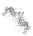
以下、本発明を実施した図面に基づいて構成を説明する。図1乃至図7は本発明の実施形態を示すものである。走行機体は公知のトラクタが用いられ、三点リンク方式の連結機構を有するもので、図面では省略している。 The configuration will be described below based on the drawings in which the present invention is implemented. 1 to 7 show an embodiment of the present invention. A well-known tractor is used as the traveling machine body and has a three-point link type coupling mechanism, which is omitted in the drawings.
図1において、2は機枠を示し、前方にトラクタの三点リンクに連結するためのトップブラケット15及び左右のロアピン14が設けられている。
In FIG. 1,
機枠2の後方には、左右の受金具10,10´を設けて、それぞれ支持フレーム4,4´を介して整畦作業機構1,1´を装備している。16は油圧ポンプユニットを示し、トラクタPTO軸から伝動される入力軸3によって駆動される。油圧ポンプユニット16は油圧バルブユニット18を経由して、左右の整畦作業機構1,1´に取り付けた油圧モータM1,M2のそれぞれに回転力を伝えている。油圧バルブユニット18は本実施例においては、2組の電磁油圧バルブV1,V2から構成されている。
On the rear side of the
支持フレーム4,4´の基部には支軸9,9´によって整畦作業機構1,1´を畦形成作業の位置と上方の退避位置とに上下昇降可能に配置される。支軸9はブラケット17に連結した昇降機構8である電動シリンダによって上下揺動の回動力を与えられる。
At the base of the
整畦作業機構1,1´は、掘削爪を有した盛土装置5,5´、畦上面の雑草を処理する上面処理装置7,7´及び畦の上面と側面を圧締成形する畦形成装置6,6´を備えている。13は連結アームを示し、左右の整畦作業機構1,1´を吊持している支持フレーム4間を連結している。左右の整畦作業機構1,1´は平面視で対称に構成されている。
The
24は制御ボックスを示し、電磁バルブV1,V2、作動スイッチS1,S2のメインスイッチ、整畦作業機構1,1´の昇降機構8及び盛土装置5,5´の上下揺動する昇降シリンダ22のスイッチ等を有し、トラクタ駆動のバッテリと連結され通常はトラクタ運転席の近傍へ備えておく。
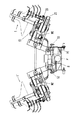
図2は一側部が整畦作業位置に位置させて、他側部は非作業位置である上方の退避位置に対抗させた状態の後面図である。 FIG. 2 is a rear view of a state in which one side portion is positioned at the trimming work position and the other side portion is opposed to an upper retreat position that is a non-working position.
この後面図の右側一側は、機枠2に対して支持フレーム4が水平状に保持されて整畦作業機構1を畦の成形作業位置に設定されている。機枠2の中央部に配置されている油圧ポンプユニット16は2組の電磁油圧バルブV1,V2を経由して、左右の整畦作業機構1,1´の入力部を形成する第1伝動ケース19,19´へ回動力を伝える。第1伝動ケース19,19´は上面処理装置を形成する破砕刃の回転軸を回転すると同時に第2伝動ケース20,20´及び第3伝動ケース21,21´を駆動する。
On the right side of the rear view, the
第2伝動ケース20,20´は、畦形成装置6,6´を形成する円錐ディスクの回転軸を駆動するものである。第3伝動ケース21,21´は盛土装置5,5´を形成する掘削刃の回転軸を駆動する。
The
後面視の他側側の整畦作業機構1´は、昇降機構8の電動シリンダが最短に伸縮調整された状態を示し、一側の支持フレーム4に連結された連結アーム13によって他側部の支持フレーム4´を規制して一体的に連動し支軸9´を支点として上方に揺動されて退避位置に位置している。本実施例の左右の整畦機構1,1´は昇降機構8の伸縮によって、連結アーム13によって連動して一体的に昇降するが、左右の整畦機構1,1´にそれぞれ電動シリンダや油圧シリンダを独立させて配置して畦形成作業位置と非作業位置とに昇降させてもよい。
The rear side
S1,S2は作動スイッチを示し、前記した電磁油圧バルブV1,V2と連結されており、本実施例におけるS1は後面視右側部の整畦作業機構1を吊持している支持フレーム4の下面が畦形成作業位置に設定されたとき押圧されて電機的にON状態となって回転駆動される。一方の左側部整畦作業機構1´は非作業位置である上方に位置しており、S2は支持フレーム4´の下面から開放されてOFF状態であり駆動されていない。
S1 and S2 denote operation switches, which are connected to the above-described electromagnetic hydraulic valves V1 and V2. S1 in this embodiment is the lower surface of the
図3は本発明を実施した一部を切欠いた側面図を示したもので、前方から盛土装置5,上面処理装置7及び畦形成装置6を順次配置して構成する。22は盛土装置5を上下揺動させる昇降シリンダである。23は仕切カバーを示し、盛土装置5の掘削刃によって掘削された土を畦形成装置6側へ強制案内するものである。3は入力軸を示し、後方が油圧ポンプユニット16を回転する。油圧ポンプユニット16は油圧ポンプとオイルタンクから構成されて油圧バルブユニット18へ配管される。
FIG. 3 shows a side view in which the present invention is partially cut away, and is configured by sequentially arranging a
図4は動力の伝達を示した図で、機枠2の後方中央に油圧ポンプユニット16を配置してなり、トラクタからの動力ほ自在継手25によって伝動される入力軸3と連結されている。油圧ポンプユニット16の側部には油圧バルブユニット18が設置されている。油圧バルブユニット18は2組の電磁油圧バルブV1,V2から構成されて、左右の整畦作業機構1,1´の入力部である第1伝動ケース19,19´に設けた油圧モータM1,M2へ配管されている。油圧モータM1,M2は、整畦作業機構1,1´の第1伝動ケース19へ伝動される。第1伝動ケース19の動力は、第2伝動ケース20,第3伝動ケース21ヘチェーン伝動により回転力を伝えている。
FIG. 4 is a diagram showing the transmission of power. A
図5は後面視で左側(他側部)の整畦作業機構1´側が畦形成作業位置に位置して、右側(一側側)が非作業位置である退避位置へ位置した状態を示したもので、この時昇降装置8は最大長さに伸ばした時である。この時、作動スイッチS1はOFF状態で作動スイッチS2はON状態である。
FIG. 5 shows a state in which the left side (the other side) trimming work mechanism 1 'side is located at the heel-forming work position and the right side (one side) is located at the retracted position that is the non-working position in rear view. At this time, the
図6は昇降装置8を中途に伸縮した場合で、左右両者の整畦作業機構1,1´が地上に浮上した状態で移動の際に便利である。この時、作動スイッチS1,S2は両者ともOFF状態にある。
FIG. 6 shows a case where the
図7は油圧ポンプユニット16の動作を示すフロー図であり、油圧ポンプPは入力軸3より回動力を与えられると左右の整畦作業機構1,1´を駆動する油圧モータM1,M2の駆動切換をする2系統の電磁油圧バルブV1,V2が配置される。作動スイッチS1,S2は整畦作業機構1,1´がそれぞれ整畦作業位置に設定した時にONされて自動的に駆動され、非作業位置である上方へ回動した時にOFF状態となる。又、作動スイッチS1,S2を設けない場合は、制御ボックス24に対して電磁油圧バルブV1,V2へのON,OFFを指示するスイッチを設ければよい。
FIG. 7 is a flowchart showing the operation of the
1,1´ 整畦作業機構
2 機枠
3 入力軸
4,4´ 支持フレーム
5,5´ 盛土装置
6,6´ 畦形成装置
7,7´ 上面処理装置
8 昇降機構
9,9´ 支軸
10,10´ 受金具
13 連結アーム
14 ロアピン
15 トップブラケット
16 油圧ポンプユニット
17 ブラケット
18 油圧バルブユニット
19,19´ 第1伝動ケース
20,20´ 第2伝動ケース
21,21´ 第3伝動ケース
22 昇降シリンダ
23 仕切カバー
24 制御ボックス
25 自在継手
M1,M2 油圧モータ
S1,S2 作動スイッチ
1, 1 '
Claims (1)
The machine frame is connected to the tractor by the connection mechanism, and the trimming work mechanisms are separately arranged on the left and right sides of the machine frame in the traveling direction. In a scissor forming machine provided with a vertical elevating device located at the scissor working position and the other in the upper retracted position, the machine frame is provided with a hydraulic pump unit input from the tractor, A tractor characterized in that a separate hydraulic motor is provided in the trimming work mechanism, and the hydraulic pump unit and the hydraulic motor are piped through hydraulic valves to switch the drive of the left and right trimming work mechanisms. Linking machine.
Priority Applications (1)
| Application Number | Priority Date | Filing Date | Title |
|---|---|---|---|
| JP2004118853A JP2005295927A (en) | 2004-04-14 | 2004-04-14 | Levee forming machine to be connected to tractor |
Applications Claiming Priority (1)
| Application Number | Priority Date | Filing Date | Title |
|---|---|---|---|
| JP2004118853A JP2005295927A (en) | 2004-04-14 | 2004-04-14 | Levee forming machine to be connected to tractor |
Publications (1)
| Publication Number | Publication Date |
|---|---|
| JP2005295927A true JP2005295927A (en) | 2005-10-27 |
Family
ID=35328222
Family Applications (1)
| Application Number | Title | Priority Date | Filing Date |
|---|---|---|---|
| JP2004118853A Pending JP2005295927A (en) | 2004-04-14 | 2004-04-14 | Levee forming machine to be connected to tractor |
Country Status (1)
| Country | Link |
|---|---|
| JP (1) | JP2005295927A (en) |
Cited By (4)
| Publication number | Priority date | Publication date | Assignee | Title |
|---|---|---|---|---|
| JP2012085536A (en) * | 2010-10-15 | 2012-05-10 | Matsuyama Plow Mfg Co Ltd | Levee plastering machine |
| JP2013179847A (en) * | 2012-02-29 | 2013-09-12 | Fuji Trailer Manufacturing Co Ltd | Levee shaping machine |
| JP2013201926A (en) * | 2012-03-27 | 2013-10-07 | Fuji Trailer Manufacturing Co Ltd | Levee-shaping machine |
| JP2013255446A (en) * | 2012-06-12 | 2013-12-26 | Fuji Trailer Manufacturing Co Ltd | Ridge leveling machine |
-
2004
- 2004-04-14 JP JP2004118853A patent/JP2005295927A/en active Pending
Cited By (4)
| Publication number | Priority date | Publication date | Assignee | Title |
|---|---|---|---|---|
| JP2012085536A (en) * | 2010-10-15 | 2012-05-10 | Matsuyama Plow Mfg Co Ltd | Levee plastering machine |
| JP2013179847A (en) * | 2012-02-29 | 2013-09-12 | Fuji Trailer Manufacturing Co Ltd | Levee shaping machine |
| JP2013201926A (en) * | 2012-03-27 | 2013-10-07 | Fuji Trailer Manufacturing Co Ltd | Levee-shaping machine |
| JP2013255446A (en) * | 2012-06-12 | 2013-12-26 | Fuji Trailer Manufacturing Co Ltd | Ridge leveling machine |
Similar Documents
| Publication | Publication Date | Title |
|---|---|---|
| JP2005295927A (en) | Levee forming machine to be connected to tractor | |
| US6662480B1 (en) | Bucket level | |
| CN117587684A (en) | Milling accessories | |
| JP2005295933A (en) | Levee forming machine | |
| JP4773863B2 (en) | Hydraulic excavator and three-point support mounting device | |
| JP2019187364A (en) | Working machine | |
| CN220202408U (en) | Milling attachment | |
| JP2019170239A (en) | Working machine | |
| JP2009142152A (en) | Levee plastering machine | |
| JP2722399B2 (en) | Farm work machine | |
| JP2005295880A (en) | Levee forming machine | |
| US2179765A (en) | Walking tractor | |
| JP2022119074A (en) | Work machine | |
| JP4285686B2 (en) | Cocoon forming machine | |
| JP3042291U (en) | Work attachment for earthworking machinery | |
| JP4264586B2 (en) | Koji forming machine connected to tractor | |
| JP5358786B2 (en) | Cocoon forming machine | |
| JP5682921B2 (en) | Offset work machine | |
| JP2025123935A (en) | Work machinery | |
| JP2003230302A (en) | Ridger | |
| JP2025119696A (en) | Work machinery | |
| JPS5828042Y2 (en) | excavation work vehicle | |
| JP4496129B2 (en) | Ditcher | |
| JP2004081037A (en) | Agricultural implement | |
| JPH0324688Y2 (en) |