JP2005295893A - Light reflector - Google Patents
Light reflector Download PDFInfo
- Publication number
- JP2005295893A JP2005295893A JP2004117029A JP2004117029A JP2005295893A JP 2005295893 A JP2005295893 A JP 2005295893A JP 2004117029 A JP2004117029 A JP 2004117029A JP 2004117029 A JP2004117029 A JP 2004117029A JP 2005295893 A JP2005295893 A JP 2005295893A
- Authority
- JP
- Japan
- Prior art keywords
- rotating body
- rotation
- body unit
- unit
- light
- Prior art date
- Legal status (The legal status is an assumption and is not a legal conclusion. Google has not performed a legal analysis and makes no representation as to the accuracy of the status listed.)
- Granted
Links
Images
Landscapes
- Catching Or Destruction (AREA)
- Illuminated Signs And Luminous Advertising (AREA)
Abstract
Description
本発明は、光反射装置に関するものである。 The present invention relates to a light reflecting device.
従来、家庭用、産業用等の各種の機械装置、例えば、送風装置、空気調和装置等においては、電源を投入することによってモータ、圧縮機等が駆動され、機械装置が稼動されるようになっている。 Conventionally, in various mechanical devices for home use, industrial use, etc., for example, a blower device, an air conditioner device, etc., by turning on the power, the motor, the compressor, etc. are driven to operate the mechanical device. ing.
この場合、機械装置が稼動されるのに伴って所定の振動が発生するので、操作者等は、振動を認識することによって機械装置が稼動されているかどうかを判断することができる。 In this case, since a predetermined vibration is generated as the mechanical device is operated, an operator or the like can determine whether the mechanical device is operated by recognizing the vibration.
また、従来、鳩(はと)、猫、野性動物等の動物類が、庭、ベランダ等に侵入して糞(ふん)等で汚したり、畑等に侵入して作物を荒らしたりするのを防止するための動物類排斥装置、例えば、鳩がベランダに侵入するのを防止するための鳩避け装置が提供されている(例えば、特許文献1参照。)。 Conventionally, animals such as pigeons, cats, wild animals, etc. invade gardens, verandas, etc. and become dirty with feces, etc., or invade fields to destroy crops. Animal evacuation devices for prevention, for example, dove avoidance devices for preventing doves from entering the veranda are provided (for example, see Patent Document 1).
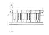
図2は従来の鳩避け装置の概略図である。 FIG. 2 is a schematic view of a conventional pigeon avoidance device.
図において、1はゴム紐(ひも)であり、該ゴム紐1の両端に取付手段3が配設され、該取付手段3を介してゴム紐1をベランダ11の垂直部材13に取り付けるようになっている。また、前記ゴム紐1から複数の揺動紐7が垂下させられる。この場合、該各揺動紐7が風等によって独立して揺動させられると、鳩は揺動紐7を忌避するので、鳩がベランダ11に進入するのを防止することができる(例えば、特許文献1参照。)。
しかしながら、前記従来の機械装置においては、発生する振動が小さい場合、機械装置が稼動されているかどうかを判断することが困難になり、機械装置が稼動されているにもかかわらず電源を投入するつもりで切ってしまい、機械装置の稼動を停止させてしまうことがある。例えば、空気調和装置等のような、圧縮式冷凍機械によって構成される機械装置においては、稼動中に誤って電源を切ると、圧縮機を保護するために所定の時間だけ再稼動が禁止されるようになっているので、機械装置の操作性が低くなってしまう。 However, in the conventional mechanical device, when the generated vibration is small, it is difficult to determine whether the mechanical device is operated, and the power is turned on even though the mechanical device is operated. May cause the machine to stop operating. For example, in a mechanical device constituted by a compression refrigeration machine such as an air conditioner, if the power is accidentally turned off during operation, reactivation is prohibited for a predetermined time in order to protect the compressor. As a result, the operability of the mechanical device is lowered.
また、従来の鳩避け装置においては、前記所定の長さを有するゴム紐1を前記垂直部材13に取り付ける必要があり、さらに、ゴム紐1から所定の長さを有する複数の揺動紐7を垂下させる必要があるので、鳩避け装置が大型化するだけでなく、ベランダ11の美観を損ねるとともに、鳩避け装置の保守・管理が煩わしい。
Further, in the conventional pigeon avoiding device, it is necessary to attach the
本発明は、前記従来の機械装置、鳩避け装置等の問題点を解決して、機械装置に適用した場合、機械装置が稼動されているかどうかを容易に認識することができ、動物類排斥装置に適用した場合、動物類排斥装置を小型化することができ、美観を損ねることがなく、保守・管理を容易に行うことができる光反射装置を提供することを目的とする。 The present invention solves the problems of the conventional mechanical device, the pigeon avoiding device, etc., and when applied to the mechanical device, it can easily recognize whether the mechanical device is in operation or not. When applied to the above, an object of the present invention is to provide a light reflecting device that can reduce the size of an animal evacuation device and that can be easily maintained and managed without impairing aesthetics.
そのために、本発明の光反射装置においては、駆動部を駆動することによって発生させられた回転を受ける回転入力部と、反射部を備えた回転体ユニットと、前記回転入力部に対して回転体ユニットを相対的に回転自在に支持し、回転入力部によって受けられた回転を回転体ユニットに伝達する支持機構部とを有する。 Therefore, in the light reflecting device of the present invention, the rotation input unit that receives the rotation generated by driving the drive unit, the rotating body unit including the reflecting unit, and the rotating body with respect to the rotation input unit A support mechanism that supports the unit relatively rotatably and transmits rotation received by the rotation input unit to the rotating body unit.
本発明によれば、光反射装置においては、駆動部を駆動することによって発生させられた回転を受ける回転入力部と、反射部を備えた回転体ユニットと、前記回転入力部に対して回転体ユニットを相対的に回転自在に支持し、回転入力部によって受けられた回転を回転体ユニットに伝達する支持機構部とを有する。 According to the present invention, in the light reflecting device, the rotation input unit that receives the rotation generated by driving the drive unit, the rotating body unit including the reflecting unit, and the rotating body with respect to the rotation input unit. A support mechanism that supports the unit relatively rotatably and transmits rotation received by the rotation input unit to the rotating body unit.
この場合、回転体ユニットは反射部を備えるので、光反射装置を機械装置に適用した場合、機械装置が稼動されているかどうかを容易に認識することができる。 In this case, since the rotating body unit includes the reflecting portion, when the light reflecting device is applied to the mechanical device, it is possible to easily recognize whether the mechanical device is in operation.
また、駆動部からの回転を回転体ユニットに伝達し、回転体ユニットを回転させるだけでよいので、光反射装置を動物類排斥装置に適用した場合、動物類排斥装置を小型化することができるだけでなく、美観を損ねることがなく、動物類排斥装置の保守・管理を容易に行うことができる。 Further, since it is only necessary to transmit the rotation from the drive unit to the rotator unit and rotate the rotator unit, when the light reflecting device is applied to the animal sterilizer, the animal sterilizer can only be miniaturized. In addition, maintenance and management of the animal excretion device can be easily performed without impairing the beauty.
以下、本発明の実施の形態について図面を参照しながら詳細に説明する。なお、この場合、光反射装置を、機械装置に搭載される稼働表示装置、及び動物類排斥装置に適用する場合について説明する。 Hereinafter, embodiments of the present invention will be described in detail with reference to the drawings. In this case, a case will be described in which the light reflecting device is applied to an operation display device mounted on a mechanical device and an animal exclusion device.
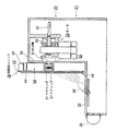
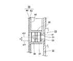
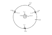
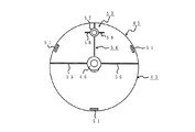
図1は本発明の実施の形態における光反射装置の概略を示す断面図、図3は本発明の実施の形態における回転体ユニットの支持構造を示す断面図、図4は本発明の実施の形態における支持プレートの正面図、図5は本発明の実施の形態における支持プレートの背面図である。 FIG. 1 is a cross-sectional view showing an outline of a light reflecting device in an embodiment of the present invention, FIG. 3 is a cross-sectional view showing a support structure of a rotating body unit in the embodiment of the present invention, and FIG. 4 is an embodiment of the present invention. FIG. 5 is a rear view of the support plate according to the embodiment of the present invention.
図において、21は中空の筐(きょう)体であり、該筐体21は、ベース部22、及び該ベース部22から上方に向けて突出させて形成された垂直部23を備え、前記ベース部22の上面に、垂直部23の前端面(図1において左端面)に向けて光を照射する光源としてのランプ26が取り付けられる。
In the figure,
また、前記垂直部23内の所定の箇所には、駆動源としての、かつ、駆動部としてのモータ28が、ブラケット29を介して筐体21に取り付けられる。前記モータ28の出力軸31は、垂直部23の前壁32に形成された貫通穴33を貫通して前方(図1及び3において左方)に向けて延びる。そして、前記出力軸31に、複数の、本実施の形態においては、2個のベアリング36、37を介して、被駆動体としての回転体ユニット39が取付けられ、該回転体ユニット39は出力軸31に対して相対的に回転自在に支持される。なお、本実施の形態において、前記出力軸31は、モータ28を構成する要素であるが、モータ28を駆動することによって発生させられた回転を受ける回転入力部としても機能する。
A
前記ベアリング36、37は、ころがり軸受けから成り、モータ28の駆動に伴って出力軸31が回転させられたときに、回転体ユニット39に回転を伝達する。そして、前記ベアリング36、37は、軸方向において所定のクリアランスを置いて配設され、モータ28の回転を回転体ユニット39に伝達するための回転伝達系及び支持機構部を構成する。なお、回転体ユニット39は、ベアリング36、37を介して出力軸31に取り付けられるので、前記モータ28の駆動を開始するのに伴って、出力軸31は所定の回転速度で回転させられるが、回転体ユニット39は、慣性モーメントによって、停止させられた状態から、徐々に回転速度を高くして回転させられ、所定の時間が経過すると、一定の回転速度で回転させられる。また、41はベアリング37を位置決めする位置決め用のリングである。
The
前記回転体ユニット39は、円形の形状を有する支持部材としての支持プレート43、及び円形の形状を有し、前記支持プレート43の前端面に当接させて、着脱自在に取り付けられた反射部材44を備える。前記回転体ユニット39は、前記出力軸31に対して偏心させて配設され、そのために、回転体ユニット39の軸心sh1が出力軸31の軸心sh2に対して偏位量δだけ異ならせて設定される。したがって、前記回転体ユニット39を回転させると、反射部材44は前記軸心sh2によって表される回転中心に対して偏心して回転する。
The rotating body unit 39 has a
前記支持プレート43は、例えば、ABS樹脂によって形成され、偏平な環状のフランジ部45、及び該フランジ部45の内周縁から後方(図1及び3において右方)に突出させて形成された筒状部としてのボス46を備え、該ボス46によって前記ベアリング36、37が包囲される。そのために、前記ボス46は、支持プレート43の中心となる前記軸心sh1から前記偏位量δだけ偏心させて形成され、各ベアリング36、37のインナレース内に出力軸31が圧入され、ボス46内に各ベアリング36、37のアウタレースが圧入される。
The
そして、前記フランジ部45の円周方向における複数箇所、本実施の形態においては、3箇所に、外周縁の近傍から前方に突出させて、係止部としての保持爪48が形成され、該保持爪48に前記反射部材44を係止させることによって、該反射部材44を支持プレート43に取り付けることができる。なお、前記フランジ部45における各保持爪48よりわずかに径方向内方には、保持爪48と同様の円周方向長さを有するスリット51が形成される。したがって、各スリット51より径方向外方のブリッジ部分を変形させながら、保持爪48に反射部材44を係止させることができるので、反射部材44の取付作業を簡素化することができる。
And the
ところで、前記モータ28を駆動して回転体ユニット39を回転させるに当たり、出力軸31に対して回転体ユニット39が偏心させられるので、出力軸31に偏荷重が加わると、回転体ユニット39に振動が発生し、光反射装置の全体にも振動が発生してしまう。そこで、回転体ユニット39の回転に伴って出力軸31に偏荷重が加わらないように、支持プレート43における軸心sh1からみて軸心sh2側の部分(図において上半分)に、バランス装置53が形成される。該バランス装置53は、前記ボス46から軸心sh1とは反対側に外周縁まで延びる第1のリブ54、前記ボス46から第1のリブ54と直角の方向に、外周縁まで延びる第2、第3のリブ55、56、前記第1のリブ54における外周縁の近傍に、円筒状に形成された筒状突起57、該筒状突起57の外周面から前記第2、第3のリブ55、56と平行に所定の距離だけ延在させて形成された第4、第5のリブ58、59、及び前記筒状突起57内にねじ込まれる図示されないねじ等から成り、回転バランスを採る。
By the way, when rotating the rotating body unit 39 by driving the
前記第1〜第5のリブ54〜56、58、59及び筒状突起57は、いずれも後方に向けて突出させて形成され、前記第1〜第5のリブ54〜56、58、59及びねじは、回転体ユニット39を所定の回転速度の範囲で回転させたときに、振動が発生するのを防止することができるような位置及び寸法が設定される。なお、回転体ユニット39は、第1〜第5のリブ54〜56、58、59による空気抵抗、及びベアリング36、37自体による摩擦抵抗を受けながら回転させられるので、定常状態における回転体ユニット39の回転速度は出力軸31の回転速度より低く(二分の一程度に)なる。また、回転体ユニット39の回転速度は、第1〜第5のリブ54〜56、58、59の寸法、取付角度等を変更したりベアリングの数を増減したりすることによって変化させることができる。
The first to fifth ribs 54 to 56, 58, 59 and the
そして、前記反射部材44の一方の面、本実施の形態においては、ランプ26と対向する前端面に反射部としての反射面が形成され、該反射面には、図示されない微細パターンが同心状に、又は螺(ら)旋状に形成される。そのために、前記反射部材44は、例えば、ポリカーボネート等の樹脂から成り、一方の面に微細な凹凸が形成された第1の保護層、該第1の保護層の上面に、アルミニウム等のメッキ処理等によって形成された反射層、該反射層の上面に形成され、ポリカーボネート等の樹脂から成る第2の保護層等を備える。
A reflective surface as a reflective portion is formed on one surface of the
なお、反射部材44として、CD−R、DVD等のディスク基板を使用し、該ディスク基板の微細パターンが形成された記録面を反射面として使用することができる。
Note that a disk substrate such as a CD-R or DVD can be used as the reflecting
ところで、前記反射面の微細パターンは、光に対する性質が周期的に変化するように形成されるので、反射面に光を照射すると、光が回折する。したがって、白色光を反射面に向けて照射すると、光の波長によって回折する角度が異なるので、光が虹色に分光させられる。 By the way, the fine pattern of the reflection surface is formed so that the property with respect to light periodically changes. Therefore, when the reflection surface is irradiated with light, the light is diffracted. Therefore, when irradiating white light toward the reflecting surface, the angle of diffraction differs depending on the wavelength of the light, so that the light is dispersed into a rainbow color.
本実施の形態においては、前記回転体ユニット39を回転させると、反射部材44は回転中心に対して偏心しながら回転するので、前記反射面において光の照射される角度が変化することになる。したがって、回転体ユニット39の回転に伴って、虹色の光が、異なる位置及び角度で発生させられることになる。
In the present embodiment, when the rotating body unit 39 is rotated, the reflecting
また、回転体ユニット39の回転を開始する際に、出力軸31はモータ28のトルクを受けて回転させられるのに対して、回転体ユニット39は慣性モーメントによって停止した状態を維持しようとする。このとき、ベアリング36、37が空転するので、モータ28に加わる負荷を極めて小さくすることができる。したがって、モータ28に必要とされるトルクを小さくすることができるので、モータ28を小型化することができ、モータ28によって発生させられる騒音を小さくすることができる。また、モータ28を駆動することによって消費される電力を小さくすることができる。
Further, when the rotation of the rotating body unit 39 is started, the
そして、ベアリング36、37は、それ自体が有する摩擦抵抗によって、モータ28のトルクを伝達するので、回転体ユニット39に伝達されるトルクは極めて小さい。したがって、わずかな力を加えるだけで回転体ユニット39を停止させることができ、誤って回転体ユニット39に触れても怪我をすることはない。また、回転体ユニット39を強制的に停止させても、モータ28に負荷が加わることがない。
And since the
そして、前記回転体ユニット39は二つのベアリング36、37を介して支持されるので、機械的ながたつきを無くすことができる。したがって、回転体ユニット39を安定させて回転させることができるだけでなく、回転体ユニット39によって騒音が発生するのを防止することができる。
And since the said rotary body unit 39 is supported via the two
本実施の形態において、前記ランプ26は、図示されない所定の支持機構によって支持され、所定の角度で傾斜させて配設され、反射部材44の反射面のうちの、主として下半部を照射するようになっているが、反射面の全体を照射することもできる。また、ランプ26の傾き、及び前後方向における位置は、前記支持機構を調整することによって変更することができる。
In the present embodiment, the
さらに、本実施の形態においては、回転体ユニット39を出力軸31に対して直角の方向に取り付けるようになっているが、回転体ユニット39を出力軸31に対して傾斜させて取り付けることができる。また、本実施の形態においては、前記回転体ユニット39を軸心sh2を回転中心として回転させるようになっているが、所定の軸を中心にして揺動させることもできる。
Furthermore, in the present embodiment, the rotating body unit 39 is attached in a direction perpendicular to the
前記構成の光反射装置を機械装置、例えば、送風装置が稼動されているかどうかを表示する稼動表示装置に適用する場合、前記光反射装置を機械装置の筐体に組み込むのが好ましい。その場合、前記出力軸31と一体に出力軸30が形成され、該出力軸30を介して図示されない他の要素、例えば、送風用のファンに回転を伝達することができる。
When the light reflecting device having the above-described configuration is applied to a mechanical device, for example, an operation display device that displays whether or not a blower device is operated, the light reflecting device is preferably incorporated in a housing of the mechanical device. In this case, the
そして、操作者が、送風装置の電源を投入すると、光反射装置の図示されない制御部の回転処理手段は、回転処理を行い、ランプ26を点灯するとともに、モータ28を駆動して所定の回転速度で送風ファンを回転させて風を起こすとともに、前記回転体ユニット39を回転させる。それに伴って、ランプ26から放射された光が反射部材44の反射面に当たり、虹色の光を、異なる位置及び角度で発生させる。
Then, when the operator turns on the power of the air blower, the rotation processing means of the control unit (not shown) of the light reflecting device performs the rotation processing, lights the
したがって、送風装置において発生する振動が小さい場合でも、操作者等は、前記反射面を見るだけで送風装置が稼動されているかどうかを容易に認識することができる。その結果、送風装置の操作性を高くすることができる。 Therefore, even when the vibration generated in the blower is small, an operator or the like can easily recognize whether or not the blower is operating only by looking at the reflection surface. As a result, the operability of the blower can be increased.
また、前記構成の光反射装置を動物類排斥装置に適用する場合、前記ベース部22の前端(図1において左端)に、鳩、猫、野性動物等の動物類が近づいたときに、動物類をその動きによって検出する検出部としての感知センサ25が取り付けられる。したがって、動物類が動物類排斥装置に接近するのに伴って前記感知センサ25によって動物類の動きが検出され、センサ出力が前記制御部に送られる。そして、前記回転処理手段は、回転処理を行い、ランプ26を点灯するとともに、モータ28を駆動して所定の回転速度で回転体ユニット39を回転させる。それに伴って、ランプ26から放射された光が反射部材44の反射面に当たり、虹色の光を、異なる位置及び角度で発生させる。
Further, when the light reflecting device having the above-described configuration is applied to an animal exclusion device, when animals such as pigeons, cats, wild animals, etc. approach the front end (left end in FIG. 1) of the
なお、前記回転処理手段は、所定のタイムスケジュールでモータ28の回転速度を変化させることができ、その場合、虹色の光が発生する位置及び角度を複雑に変化させることができる。したがって、動物類は、光の変化を嫌うので、前記構成の動物類排斥装置を庭、ベランダ、畑等に置くと、動物類が庭、ベランダ、畑等に侵入するのを防止することができる。
The rotation processing means can change the rotation speed of the
このように、モータ28からの回転を回転体ユニット39に伝達し、該回転体ユニット39を回転させるだけでよいので、動物類排斥装置を小型化することができる。また、庭、ベランダ、畑等に置いたときに、美観を損ねることがない。
Thus, since the rotation from the
そして、反射部材44が汚れても、反射面に第2の保護層が形成されているので、汚れを簡単に拭(ふ)き取ることができる。また、反射面が劣化した場合には、反射部材44を容易に交換することができるので、動物類排斥装置の保守・管理を容易に行うことができる。
Even if the reflecting
本実施の形態においては、光反射装置を稼働表示装置、及び動物類排斥装置に適用した例について説明しているが、光反射装置を、装飾用、ディスプレイ用等として使用することができる。 In this embodiment, an example in which the light reflection device is applied to an operation display device and an animal excretion device is described. However, the light reflection device can be used for decoration, display, and the like.
なお、本発明は前記実施の形態に限定されるものではなく、本発明の趣旨に基づいて種々変形させることが可能であり、それらを本発明の範囲から排除するものではない。 In addition, this invention is not limited to the said embodiment, It can change variously based on the meaning of this invention, and does not exclude them from the scope of the present invention.
28 モータ
31 出力軸
36、37 ベアリング
39 回転体ユニット
28
Claims (1)
(b)反射部を備えた回転体ユニットと、
(c)前記回転入力部に対して回転体ユニットを相対的に回転自在に支持し、回転入力部によって受けられた回転を回転体ユニットに伝達する支持機構部とを有することを特徴とする光反射装置。 (A) a rotation input unit that receives the rotation generated by driving the drive unit;
(B) a rotating body unit provided with a reflecting portion;
(C) a light having a support mechanism unit that rotatably supports the rotary unit with respect to the rotary input unit and transmits the rotation received by the rotary input unit to the rotary unit. Reflector.
Priority Applications (1)
| Application Number | Priority Date | Filing Date | Title |
|---|---|---|---|
| JP2004117029A JP3828551B2 (en) | 2004-04-12 | 2004-04-12 | Light reflector |
Applications Claiming Priority (1)
| Application Number | Priority Date | Filing Date | Title |
|---|---|---|---|
| JP2004117029A JP3828551B2 (en) | 2004-04-12 | 2004-04-12 | Light reflector |
Publications (2)
| Publication Number | Publication Date |
|---|---|
| JP2005295893A true JP2005295893A (en) | 2005-10-27 |
| JP3828551B2 JP3828551B2 (en) | 2006-10-04 |
Family
ID=35328189
Family Applications (1)
| Application Number | Title | Priority Date | Filing Date |
|---|---|---|---|
| JP2004117029A Expired - Lifetime JP3828551B2 (en) | 2004-04-12 | 2004-04-12 | Light reflector |
Country Status (1)
| Country | Link |
|---|---|
| JP (1) | JP3828551B2 (en) |
Cited By (1)
| Publication number | Priority date | Publication date | Assignee | Title |
|---|---|---|---|---|
| JP2013532983A (en) * | 2010-07-14 | 2013-08-22 | インビジ・シールド・リミテッド | Methods and systems for driving away animals |
-
2004
- 2004-04-12 JP JP2004117029A patent/JP3828551B2/en not_active Expired - Lifetime
Cited By (2)
| Publication number | Priority date | Publication date | Assignee | Title |
|---|---|---|---|---|
| JP2013532983A (en) * | 2010-07-14 | 2013-08-22 | インビジ・シールド・リミテッド | Methods and systems for driving away animals |
| JP2018050635A (en) * | 2010-07-14 | 2018-04-05 | インビジ・シールド・リミテッド | Method and system for deterring animals |
Also Published As
| Publication number | Publication date |
|---|---|
| JP3828551B2 (en) | 2006-10-04 |
Similar Documents
| Publication | Publication Date | Title |
|---|---|---|
| US20210180602A1 (en) | Ceiling fan with concentric stationary tube and power-down features | |
| US8876468B2 (en) | Ceiling fan with concentric stationary tube and power-down features | |
| KR101616684B1 (en) | Electric fan having user following function | |
| US8297945B2 (en) | Axial fan | |
| MX2010009777A (en) | Ceiling fan system with brushless motor. | |
| CA2688986A1 (en) | Rotating light | |
| US7578204B2 (en) | Gobo wheel location drive | |
| TW200742801A (en) | Fan and impeller thereof | |
| CN107327758B (en) | Angle adjusting device and lighting device | |
| JP3828551B2 (en) | Light reflector | |
| US7428087B1 (en) | Mirror structure for laser printer | |
| CN1178809C (en) | Intruder Detectors and Controllers | |
| KR100749725B1 (en) | Dome type infrared ray sensors | |
| US6022189A (en) | Ceiling fan having a rotatable inner housing | |
| KR101578185B1 (en) | large beacon | |
| JP3416775B2 (en) | Ceiling fan with illuminator | |
| JP2005353414A (en) | Lighting system and light-diffusing type alarm lamp | |
| CN222186830U (en) | A warning light with protective performance | |
| JP2510432Y2 (en) | Rotating drum position detector for pachinko machines | |
| US5975848A (en) | Ceiling fan having rotary inner housing | |
| US20240350693A1 (en) | System and cartridge for dispensing a fragrance | |
| JP2007066543A (en) | Small revolving light | |
| KR101903156B1 (en) | PTZ Camera with rotation structure of Camera head | |
| DE602004026139D1 (en) | vehicle hub | |
| JP3221792U (en) | Air blower with lighting function |
Legal Events
| Date | Code | Title | Description |
|---|---|---|---|
| A621 | Written request for application examination |
Free format text: JAPANESE INTERMEDIATE CODE: A621 Effective date: 20040412 |
|
| A977 | Report on retrieval |
Free format text: JAPANESE INTERMEDIATE CODE: A971007 Effective date: 20060420 |
|
| A131 | Notification of reasons for refusal |
Free format text: JAPANESE INTERMEDIATE CODE: A131 Effective date: 20060516 |
|
| A521 | Written amendment |
Free format text: JAPANESE INTERMEDIATE CODE: A523 Effective date: 20060606 |
|
| TRDD | Decision of grant or rejection written | ||
| A01 | Written decision to grant a patent or to grant a registration (utility model) |
Free format text: JAPANESE INTERMEDIATE CODE: A01 Effective date: 20060704 |
|
| A61 | First payment of annual fees (during grant procedure) |
Free format text: JAPANESE INTERMEDIATE CODE: A61 Effective date: 20060706 |
|
| R150 | Certificate of patent or registration of utility model |
Free format text: JAPANESE INTERMEDIATE CODE: R150 |
|
| FPAY | Renewal fee payment (event date is renewal date of database) |
Free format text: PAYMENT UNTIL: 20100714 Year of fee payment: 4 |
