JP2005295864A - Degreasing equipment - Google Patents
Degreasing equipment Download PDFInfo
- Publication number
- JP2005295864A JP2005295864A JP2004115557A JP2004115557A JP2005295864A JP 2005295864 A JP2005295864 A JP 2005295864A JP 2004115557 A JP2004115557 A JP 2004115557A JP 2004115557 A JP2004115557 A JP 2004115557A JP 2005295864 A JP2005295864 A JP 2005295864A
- Authority
- JP
- Japan
- Prior art keywords
- mesh
- grain
- rotor
- hitting
- forced
- Prior art date
- Legal status (The legal status is an assumption and is not a legal conclusion. Google has not performed a legal analysis and makes no representation as to the accuracy of the status listed.)
- Granted
Links
Images

Landscapes
- Threshing Machine Elements (AREA)
Abstract
【課題】 本発明の課題は、穀稈の穂部に対して、横から叩打して適当な目合と線径の網状体に高速で衝突させることにより、穀粒に対し曲げ荷重を作用させて脱粒性を高め、穂切れの発生をなくし完全な単粒化を図ることにある。
【解決手段】 本発明は、挟持搬送される穀稈の穂部に対し、横から強制打撃を付与し対向側の網状体に衝突させて脱粒する強制打撃ロ−タを設けてあることを特徴とする。また、前記網状体は目合のピッチを株元側より穂先側において密に構成してあることを特徴とする。また、前記網状体の上手側にはこの網目を通して選別風を圧送する風選手段を設けてあることを特徴とする。また、前記強制打撃ロ−タは、表面が網体で略楕円形に構成され、穀稈の穂部を挟んだ状態で交互に叩き合い、互いに受け合うように一対設けて対向配置してあることを特徴とする。
【選択図】 図2PROBLEM TO BE SOLVED: To apply a bending load to a grain by hitting the head part of the grain pod from the side and causing it to collide at high speed with a mesh having an appropriate mesh size and wire diameter. The aim is to improve the grain shedding and eliminate the occurrence of spatter and achieve a complete single grain.
SOLUTION: The present invention is characterized in that a forced hitting rotor is provided which applies a forced hitting from the side to the head part of the cereals to be sandwiched and conveyed and collides with a mesh body on the opposite side to drop the grain. And Further, the mesh body is characterized in that the mesh pitch is densely arranged on the tip side from the stock side. Further, an air selection means for pumping the selection air through the mesh is provided on the upper side of the mesh body. Further, the forced hitting rotor has a surface that is substantially oval with a net body, and is alternately struck in a state of sandwiching the ears of the cereal buds, and a pair is provided to face each other. It is characterized by that.
[Selection] Figure 2
Description
本発明は、穀稈の穂部に衝撃を付与して脱粒する脱粒装置に関し、農業機械の技術分野に属する。 TECHNICAL FIELD The present invention relates to a degranulation apparatus that applies an impact to a grain head and degranulates, and belongs to the technical field of agricultural machinery.
脱粒装置の従来技術として、挟持搬送される穀稈の穂部に対し、回転する扱歯を穀稈の稈身方向で株元側から穂先側に作用させて脱粒する円筒型扱胴(周知)によるものや、特許文献1に示されるもののように、相対向する一対の脱粒ベルト相対速度差による捻り作用で穂先部の脱粒を行うものや、また、特許文献2に示されるもののように、挟持搬送される穀稈の穂部に向けて上下から挟むように金属或は樹脂性のペレットを噴射衝突させて脱粒を行うものが存在する。
扱歯による脱粒は、穀粒に対し引張荷重であるため、穂切れ発生、藁屑発生が多く、これによって、枝梗の増発、消費馬力の増加、機外損失の増加を伴うものであった。 Since threshing by tooth-handling is a tensile load on the grain, there are many occurrences of severance and swarf generation, which was accompanied by increased branching, increased horsepower consumption, and increased loss outside the machine. .
ベルト相対速度差による脱粒は、捻り作用だけでは扱き作用があまり働かないため、充分な脱粒性能が得られない問題がある。 The degranulation due to the belt relative speed difference has a problem that a sufficient degranulation performance cannot be obtained because the handling action does not work much only by the twisting action.
また、ペレット噴射衝突による脱粒は、穀稈の穂部全ての穀粒に対してペレットを確実に作用させることが困難で脱粒残しが多く発生する。また、ペレットの回収も困難で装置が複雑化し実用に供し難いものである。 Moreover, the threshing by the pellet injection collision is difficult to cause the pellet to act reliably on all the grains of the cereal buds, and a lot of degranulation residue is generated. In addition, it is difficult to collect the pellets, which complicates the apparatus and is difficult to put into practical use.
本発明の課題とするところは、上記問題点を解消するために、穀稈の穂部に対して、これを横から叩打して適当な目合と線径の網状体に高速で衝突させることにより、穀粒に対して引張荷重でなく、曲げ荷重を作用させて脱粒性を高め、穂切れの発生をなくして完全な単粒化を図ることにある。 In order to eliminate the above-mentioned problems, the present invention aims to strike the head part of the corn straw from the side and collide with a mesh body having an appropriate mesh size and wire diameter at high speed. Therefore, it is in order to make a perfect single grain by making a grain load act on a grain rather than a tensile load, and improving grain-removing property, and eliminating the occurrence of a spike.
本発明は、上述した課題を解決するために、次の如き技術手段を講じた。すなわち、請求項1記載の本発明は、挟持搬送される穀稈の穂部に対し、横から強制打撃を付与し対向側の網状体に衝突させて脱粒する強制打撃ロ−タを設けてあることを特徴とする。
The present invention has taken the following technical means in order to solve the above-described problems. That is, the present invention according to
高速回転する強制打撃ロ−タが、挟持搬送される穀稈の穂部に対して横から叩打し、対向側に面した適当な目合を有する網状体に衝突させて脱粒する。これにより、穂部の穀粒に対して引張荷重でなく、曲げ荷重が作用するため、穂切れの発生がなく単粒化が容易となる。 A forced blow rotor that rotates at high speed strikes from the side against the ears of the cereals that are nipped and conveyed, and collides with a mesh body having an appropriate degree of mesh facing the opposite side, and threshing. Thereby, since not a tensile load but a bending load acts on the grain of the head part, there is no occurrence of ear breakage and single graining becomes easy.
請求項2記載の本発明は、請求項1において、前記網状体は目合のピッチを株元側より穂先側において密に構成してあることを特徴とする。
The present invention according to claim 2 is characterized in that, in
網の目合ピッチは、ある程度大きい(広い)方が脱粒しやすいが、枝梗付着粒が発生しやすい。逆に、ピッチが小さい(狭い)と脱粒はし難いが枝梗付着粒は発生しにくい。このことから、葉茎部の密度の高い株元側ほど目合ピッチを粗くし、穂先側ほど密にすることで、穂部の全域で均等に脱粒させることができる。 If the mesh pitch of the mesh is larger (wider) to a certain extent, it tends to fall apart, but branch raft adhering grains are more likely to occur. On the contrary, when the pitch is small (narrow), it is difficult to degranulate, but branch rachis adhering grains are difficult to occur. From this, it can be made to degranulate uniformly in the whole region of a head part by coarsening a mesh pitch as the stock source side where the density of a leaf stem part is high, and making it dense as the tip side.
請求項3記載の本発明は、請求項1又は請求項2において、前記網状体の上手側にはこの網目を通して選別風を圧送する風選手段を設けてあることを特徴とする。 According to a third aspect of the present invention, in the first or second aspect of the present invention, an air selection means is provided on the upper side of the mesh body to pump the selection air through the mesh.
選別風によって、質量の軽い葉茎部と質量の重い穂部との分離が良好に行われ穂部のみを先行して網状体に衝突させることができ、脱粒性が向上する。 By the sorting wind, the leaf stem portion having a light mass and the ear portion having a heavy mass are favorably separated, and only the ear portion can be caused to collide with the reticulate body in advance, thereby improving the grain removal property.
請求項4記載の本発明は、請求項1において、前記強制打撃ロ−タは、表面が網体で略楕円形に構成され、穀稈の穂部を挟んだ状態で交互に叩き合い、互いに受け合うように一対設けて対向配置してあることを特徴とする。 According to a fourth aspect of the present invention, in the first aspect of the present invention, the forced hitting rotor is configured such that the surface is configured in a substantially oval shape with a net body, and alternately hits each other with the ears of the cereals sandwiched between them. A pair is provided so as to accept each other, and they are arranged to face each other.
対向する一対の楕円形打撃ロ−タは、互いに逆方向に回転し、両者間を通過する穀稈の穂部に対し、一方側のロ−タが叩いたときには、この叩かれた穀稈の穂部を他方側のロ−タが表面の網体にて受けることになり、互いに叩き合い、受け合うことによって脱粒される。これにより、藁屑の発生を少なくして脱粒でき、枝梗付着粒の発生もなく、脱粒性が一層向上することになる。 A pair of opposing oval striking rotors rotate in opposite directions, and when the rotor on one side strikes the head of the cereal that passes between them, The head part is received by the rotor on the other side by the mesh body on the surface. Thereby, generation | occurrence | production of soot waste can be reduced and it can degranulate, and there is no generation | occurrence | production of branch infarction adhering grain, and degranulation property improves further.
要するに、請求項1の本発明によれば、挟持搬送される穀稈の穂部に対し、横から叩打して、対向側の網状体に衝突させることで脱粒するので、穂部の穀粒に対して引張荷重でなく、曲げ荷重が作用することになり、穂切れの発生がなく単粒化が容易で、脱粒性の向上を図ることができる。
In short, according to the present invention of
請求項2の本発明によれば、請求項1の発明による作用効果を奏するものでありながら、葉茎部の密度の高い株元側ほど網の目合ピッチを粗くし、穂先側ほど密にすることで、穂部の全域で均等に脱粒させることができる。 According to the second aspect of the present invention, while having the effect of the first aspect of the invention, the mesh pitch of the net is coarser toward the root side where the density of the leaf stem portion is higher, and closer to the tip side. By doing, it can be made to degranulate uniformly in the whole region of a head.
また、請求項3の本発明によれば、請求項1又は請求項2の発明効果を奏するものでありながら、網状体の上方からこの網目を通して選別風が圧送されるので、この選別風によって、質量の軽い葉茎部と質量の重い穂部との分離を良好確実にし、穂部のみを先行させながら網状体に衝突させることができて脱粒性が向上する。
Further, according to the present invention of
更に、請求項4の本発明によれば、互いに逆方向に回転する網状楕円形の打撃ロ−タにより、打撃ロ−タ間を通過する穀稈の穂部に対し、互いに叩き合い、且つ、互いに衝突を受け合うようにしたので、請求項1の発明効果に増して藁屑の発生、枝梗付着粒の発生をなくし、一層の脱粒性向上を図ることができる。 Further, according to the present invention of claim 4, the reticulated oval striking rotors rotating in opposite directions are struck against each other against the ears of the cereals passing between the striking rotors, and Since the collisions with each other are received, in addition to the effect of the first aspect of the invention, generation of sawdust and occurrence of branch rachis adhering grains can be eliminated, and further improvement of the degranulation property can be achieved.
以下、本発明の実施例を図面に基づいて具体的に説明する。 Embodiments of the present invention will be specifically described below with reference to the drawings.
まず、図1に示すコンバインの構成について述べる。 First, the structure of the combine shown in FIG. 1 will be described.
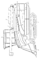
走行クロ−ラ1を具備する車体2上には、前部に昇降可能な刈取部3を、後部に脱粒装置(脱穀機)4を搭載している。刈取部3の横側部には運転部を包囲するキャビン5が設置され、その後方にはグレンタンク6が装備されている。
On a vehicle body 2 having a
つぎに、脱粒装置4の構成につき説明する。脱粒装置4の脱粒室7一側には穀稈を横倒し水平状態で挟持搬送する穀稈挟持搬送装置8が具備されている。
Next, the configuration of the degranulation apparatus 4 will be described. On the one side of the
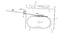
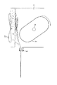
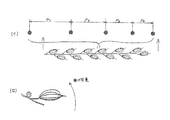
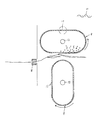
脱粒室7内には、図2及び図3に示すように、楕円形の強制打撃ロ−タ9を軸10周りに回転自在に架設し、挟持搬送される穀稈の穂部に対し、横から15m/s以上の高速で叩打させる構成としている。打撃ロ−タ9の対向側には叩打された穀稈の穂部を受け止める被衝突体として格子状或はクリンプ網状に構成された網状体11を設ける。つまり、叩打された穀稈の穂部を網状体11に衝突させることにより、穀粒の付け根部分に曲げ荷重(図4の(ロ)参照)を発生させて単粒化する構成としている。打撃ロ−タ9は、実施例では短径300ミリ、長径500ミリ程度の楕円形としてあり、該ロ−タ9と網状対11との間に穀稈を送り込むことで、穀稈の穂部が高速で叩打され上方に跳ね上げられて網状体に衝突する。この際、葉茎部は空気抵抗が大きく、比重も軽いため、穀粒付着部より速度が遅く、結果的に葉茎部から穂部の穀粒付着部が露出した形で網状体11に衝突することになる。そのため、穀粒付着部は大きな曲げ荷重を受けて、藁屑や穂切れ、枝梗付着粒を生じさせることなく確実に脱粒化することができる。
As shown in FIGS. 2 and 3, an oval forced
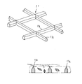
前記網状体11は、図4(イ)に示すように、網の目合ピッチP1〜P4…を穀稈の株元側ほど(P1>P2>P3>P4…)大きく(粗)し、穂先側ほど小さく(密)なるように構成して脱粒性の均等化を図るようにしている。
As shown in FIG. 4 (a), the
なお、前記網状体11において、図5に示すように、格子状網体の材質を超高分子ポリエチレンで構成し、網の断面形状を尖鋭状11aに構成しておくと、穂部が網に衝突した際に、穀粒本体が網に接触する機会が減少することになり、単粒化が容易となる。
In the
また、図2及び図3に示すように、前記網状体11の上方には、該網状体の上方からこの網目を通して下方の脱粒室7内へ選別風を圧送するための風選手段として圧風フアン12を設けることにより、質量の軽い葉茎部と質量の重い穀粒付着部との分離を促進し、穀粒付着部のみ網状体に衝突させて脱粒性の向上を図るようにしている。
Further, as shown in FIGS. 2 and 3, above the
更に、図6に示す実施例では、互いに逆方向に回転する楕円形の強制打撃ロ−タ9,9を対向させて設け、この打撃ロ−タ9,9は互いに位相を略90度ずらして回転させるようにし、両者間を通過する穀稈の穂部に対し、互いに叩き合い、且つ、互いに衝突を受け合うように構成している。そして、各ロ−タ9,9の表面は適当な目合の網状体11,11によって構成してあると共に、該ロ−タ9,9の回転速度は穀稈がロ−タ間を往復してロ−タ表面の網状体に最大速度で衝突するよう作物の種類等によって変更可能な構成としている。
Furthermore, in the embodiment shown in FIG. 6, the
このように、相対向する一対の楕円形打撃ロ−タ9,9は、互いに逆方向に回転し、両者間を通過する穀稈の穂部に対し、一方側のロ−タ9が叩いたときには、この叩かれた穀稈の穂部を他方側のロ−タ9が表面の網体11にて受けることになり、互いに叩き合い、受け合うことによって脱粒されることになる。
In this manner, the pair of opposing oval striking
次に、図7〜図9に示す別実施例について説明する。 Next, another embodiment shown in FIGS. 7 to 9 will be described.
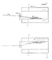
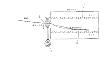
図7に示すように、線状又は板状の格子からなる網状体11,11を上下に相対向して一対設ける。この対向する網状体11,11の間隔を約300ミリ程度とし、500rpm以上の高速で上下に往復揺動させる構成とする。そして、穀稈挟持搬送装置8により挟持搬送される穀稈を揺動する網状体11,11間に送り込むことで、穀稈の穂先部分が高速で上下方向に跳ね飛ばされ、対向する網状体に衝突して脱粒されることになる。かかる構成による場合も、穀粒の付根部分に曲げ荷重を発生させて確実に単粒化することができる。図8に示す実施例は、揺動支点Pを供給される穀稈の穂先側位置に設定し、揺動駆動機構13によって穂先側より株元側を大きく揺動させる構成としている。これにより、株元側が穂先側より衝撃が大きくなり、穂先側に対し葉茎部が密集して脱粒しにくい株元側をより高速で衝突させることができ、脱粒率を穂先から株元まで均一化することができる。また、図9に示す実施例は、相対向する上下の網状体11,11に対し、この両者間に穀稈を送込供給する穀稈挟持搬送装置8を穀稈の株元側を挟持した状態で上下方向に強制揺動させることにより、穀稈の穂部側を高速で網状体11,11に衝突させて脱粒する構成としたものである。全長の長い穀稈の株元側を揺動させることで、挟持部の小さな振幅で穂先側の振幅を大きく増幅させることができ、脱粒効果を高めることができる。
As shown in FIG. 7, a pair of
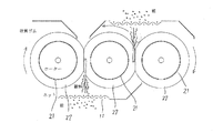
また、図10及び図11に示す実施例においては、相対向して互いに接触しながら逆方向へ回転する送込回転体21,21…と、その対向接触部の回転方向下手側に配置した格子状の網状体11とで構成され、挟持搬送される穀稈を送込回転体21,21にて挟持しながら高速で送込放出することで、網状体11に衝突させ、藁屑、穂切れ、枝梗の発生を抑制しながら、脱粒作用が効率的に行なえるようにしている。送込回転体21,21…の表面は弾性変位可能な弾性体22等で構成しておくとよい。回転体21の長さは200〜400mm程度、直径は200〜350mm程度、周速は30m/s程度あればよく、また、網状体11の目合ピッチは12mm程度、線径は2mm程度が望ましい。
Further, in the embodiment shown in FIG. 10 and FIG. 11, the feeding
なお、上記構成において、対向する回転体に周速度差を設けておくと、穀粒の付着部に捻り作用が与えられ、脱粒し易くなる。 In addition, in the said structure, if a peripheral speed difference is provided in the opposing rotary body, a twisting effect will be given to the adhesion part of a grain and it will become easy to degranulate.
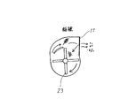
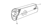
図12、図13に示す脱粒装置は、穀稈の穂先部分のみを切断して取り入れ、所定箇所に搬送した後、スロワ装置23にて網状体11に衝突させて脱粒させるように構成したものである。これによると、藁屑の発生が殆どなく、選別もそれほど要せず、直接、グレンタンクへ搬入することもできる。
12 and 13 is configured to cut and take only the tip portion of the cereal and transport it to a predetermined location, and then allow it to collide with the
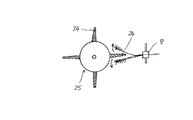
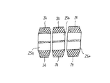
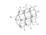
図14〜図16に示す脱粒装置は、網状叩き板24を円周上に有して回転する脱粒ロ−タ25a,25b,25c…を複数設け、それぞれ隣接するロ−タとは逆方向に回転し、網状叩き板24が挟持搬送される穀稈の穂部に対し、上から叩いたり、下から叩いたりして脱粒する構成となっている。つまり、例えば、右回転する脱粒ロ−タ25aが穀稈の穂部を上から叩いて下方に叩き落とすものとすれば、隣接の左回転する脱粒ロ−タ25bは、穀稈穂部を下から叩いて上方に叩き上げることになり、更に、これに隣接の脱粒ロ−タ25cは前記脱粒ロ−タ25aと同方向の右回転によって上から叩いて下方に叩き落とすものとなり、従って、網状叩き板24の穂先部に作用する範囲が大きくなり、脱粒能率が向上する。
The degranulation apparatus shown in FIGS. 14 to 16 is provided with a plurality of
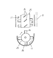
図17に開示の脱粒装置は、回転駆動可能に軸架した脱粒ロ−タ25の外周に複数の叩き羽根板26…を回転軸方向に対して斜めに設け、この高速回転する叩き羽根板26…によって挟持搬送される穀稈の穂部を叩き、脱粒ロ−タの周囲に設けた網状体11に衝突させて脱粒させる構成である。
The degranulating apparatus disclosed in FIG. 17 is provided with a plurality of
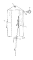
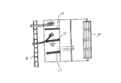
また、図18に開示の脱粒装置は、穀稈挟持搬送装置8により穀稈の株元側を挟持して、穂先側を吸引装置(吸引フアン)27で吸引しながら強制搬送するようにし、穂先側搬送経路中には複数の網状体11,11…を設置しておき、そして、吸引力で引き伸ばされながら強制搬送される穀稈の穂先部を搬送経路中の網状体11,11…に順次衝突させて脱粒させるものである。これによれば、穂先部が吸引力によって伸びた状態で網状体に衝突されるので、脱粒効果が向上し、藁屑の発生も少なく、また、脱粒後の穀粒は吸引装置で選別回収することができる。
In addition, the threshing device disclosed in FIG. 18 is configured such that the culm holding and conveying
4 脱粒装置(脱穀機) 7 脱粒室
8 穀稈挟持搬送装置 9 強制打撃ロ−タ
11 網状体 12 圧風フアン
4 Threshing device (threshing machine) 7
Claims (4)
Priority Applications (1)
| Application Number | Priority Date | Filing Date | Title |
|---|---|---|---|
| JP2004115557A JP4543248B2 (en) | 2004-04-09 | 2004-04-09 | Degreasing equipment |
Applications Claiming Priority (1)
| Application Number | Priority Date | Filing Date | Title |
|---|---|---|---|
| JP2004115557A JP4543248B2 (en) | 2004-04-09 | 2004-04-09 | Degreasing equipment |
Publications (2)
| Publication Number | Publication Date |
|---|---|
| JP2005295864A true JP2005295864A (en) | 2005-10-27 |
| JP4543248B2 JP4543248B2 (en) | 2010-09-15 |
Family
ID=35328162
Family Applications (1)
| Application Number | Title | Priority Date | Filing Date |
|---|---|---|---|
| JP2004115557A Expired - Fee Related JP4543248B2 (en) | 2004-04-09 | 2004-04-09 | Degreasing equipment |
Country Status (1)
| Country | Link |
|---|---|
| JP (1) | JP4543248B2 (en) |
Cited By (3)
| Publication number | Priority date | Publication date | Assignee | Title |
|---|---|---|---|---|
| JP2009232760A (en) * | 2008-03-27 | 2009-10-15 | Iseki & Co Ltd | Threshing apparatus |
| CN112790013A (en) * | 2020-06-05 | 2021-05-14 | 路瑶 | Separator is used in cereal production |
| CN116724763A (en) * | 2023-08-10 | 2023-09-12 | 山西农业大学高寒区作物研究所 | Threshing machine for flax |
Citations (6)
| Publication number | Priority date | Publication date | Assignee | Title |
|---|---|---|---|---|
| JPS549076U (en) * | 1977-06-22 | 1979-01-20 | ||
| JPS5451176U (en) * | 1977-09-16 | 1979-04-09 | ||
| JPS5453065U (en) * | 1977-09-21 | 1979-04-12 | ||
| JPS5642521A (en) * | 1979-09-13 | 1981-04-20 | Iseki Agricult Mach | Threshing device using compressed air |
| JPS5668319A (en) * | 1979-11-02 | 1981-06-09 | Iseki Agricult Mach | Threshing device |
| JPH11318183A (en) * | 1998-05-20 | 1999-11-24 | Kubota Corp | Threshing equipment for self-contained combine |
-
2004
- 2004-04-09 JP JP2004115557A patent/JP4543248B2/en not_active Expired - Fee Related
Patent Citations (6)
| Publication number | Priority date | Publication date | Assignee | Title |
|---|---|---|---|---|
| JPS549076U (en) * | 1977-06-22 | 1979-01-20 | ||
| JPS5451176U (en) * | 1977-09-16 | 1979-04-09 | ||
| JPS5453065U (en) * | 1977-09-21 | 1979-04-12 | ||
| JPS5642521A (en) * | 1979-09-13 | 1981-04-20 | Iseki Agricult Mach | Threshing device using compressed air |
| JPS5668319A (en) * | 1979-11-02 | 1981-06-09 | Iseki Agricult Mach | Threshing device |
| JPH11318183A (en) * | 1998-05-20 | 1999-11-24 | Kubota Corp | Threshing equipment for self-contained combine |
Cited By (4)
| Publication number | Priority date | Publication date | Assignee | Title |
|---|---|---|---|---|
| JP2009232760A (en) * | 2008-03-27 | 2009-10-15 | Iseki & Co Ltd | Threshing apparatus |
| CN112790013A (en) * | 2020-06-05 | 2021-05-14 | 路瑶 | Separator is used in cereal production |
| CN116724763A (en) * | 2023-08-10 | 2023-09-12 | 山西农业大学高寒区作物研究所 | Threshing machine for flax |
| CN116724763B (en) * | 2023-08-10 | 2023-10-24 | 山西农业大学高寒区作物研究所 | Threshing machine for flax |
Also Published As
| Publication number | Publication date |
|---|---|
| JP4543248B2 (en) | 2010-09-15 |
Similar Documents
| Publication | Publication Date | Title |
|---|---|---|
| CN107046953B (en) | Whole stalk feeding type combine harvester | |
| CN102149270B (en) | Threshing cylinder | |
| CN207185228U (en) | United reaper | |
| CN102369821B (en) | A multifunctional bionic corn thresher | |
| CN208029523U (en) | A kind of millet partly feeds sheller unit | |
| CN108142107A (en) | A kind of millet partly feeds sheller unit | |
| JP4543248B2 (en) | Degreasing equipment | |
| JP6215145B2 (en) | Combine | |
| CN202210978U (en) | Multifunctional bionic corn sheller | |
| CN108419530A (en) | The efficient low damage rape ceding of Taiwan divides standing grain device | |
| CN207519189U (en) | Threshing machine paddy separator | |
| CN103477811B (en) | It is mounted with the full stalk feed type combine harvester of sheller unit | |
| JP2010193784A (en) | Thresher | |
| CN215074035U (en) | Novel harvester grain cleaning device | |
| CN108419537A (en) | Combine harvester | |
| JP2005333891A (en) | Degreasing equipment | |
| CN2591946Y (en) | Sheller unit for combine harvester | |
| JP4630184B2 (en) | Combine | |
| JP4894135B2 (en) | Degreasing equipment | |
| CN208191409U (en) | Sheller unit | |
| JP2949037B2 (en) | Oscillating sorting mechanism of threshing equipment | |
| KR20260028498A (en) | Thresh Rotor For Combine | |
| JP5217560B2 (en) | Threshing device | |
| CN205454726U (en) | Useless stalk cuts off processing apparatus | |
| JP2022156456A (en) | General purpose combine harvester |
Legal Events
| Date | Code | Title | Description |
|---|---|---|---|
| A621 | Written request for application examination |
Free format text: JAPANESE INTERMEDIATE CODE: A621 Effective date: 20070307 |
|
| A977 | Report on retrieval |
Free format text: JAPANESE INTERMEDIATE CODE: A971007 Effective date: 20100212 |
|
| A131 | Notification of reasons for refusal |
Free format text: JAPANESE INTERMEDIATE CODE: A131 Effective date: 20100309 |
|
| A521 | Written amendment |
Free format text: JAPANESE INTERMEDIATE CODE: A523 Effective date: 20100506 |
|
| TRDD | Decision of grant or rejection written | ||
| A01 | Written decision to grant a patent or to grant a registration (utility model) |
Free format text: JAPANESE INTERMEDIATE CODE: A01 Effective date: 20100601 |
|
| A01 | Written decision to grant a patent or to grant a registration (utility model) |
Free format text: JAPANESE INTERMEDIATE CODE: A01 |
|
| A61 | First payment of annual fees (during grant procedure) |
Free format text: JAPANESE INTERMEDIATE CODE: A61 Effective date: 20100614 |
|
| FPAY | Renewal fee payment (event date is renewal date of database) |
Free format text: PAYMENT UNTIL: 20130709 Year of fee payment: 3 |
|
| R150 | Certificate of patent or registration of utility model |
Ref document number: 4543248 Country of ref document: JP Free format text: JAPANESE INTERMEDIATE CODE: R150 Free format text: JAPANESE INTERMEDIATE CODE: R150 |
|
| LAPS | Cancellation because of no payment of annual fees |