JP2005295797A - Inverter device - Google Patents
Inverter device Download PDFInfo
- Publication number
- JP2005295797A JP2005295797A JP2005155702A JP2005155702A JP2005295797A JP 2005295797 A JP2005295797 A JP 2005295797A JP 2005155702 A JP2005155702 A JP 2005155702A JP 2005155702 A JP2005155702 A JP 2005155702A JP 2005295797 A JP2005295797 A JP 2005295797A
- Authority
- JP
- Japan
- Prior art keywords
- pattern
- data
- volatile memory
- pattern operation
- undervoltage
- Prior art date
- Legal status (The legal status is an assumption and is not a legal conclusion. Google has not performed a legal analysis and makes no representation as to the accuracy of the status listed.)
- Pending
Links
Images


Landscapes
- Control Of Ac Motors In General (AREA)
- Inverter Devices (AREA)
Abstract
【課題】 揮発性メモリに記憶されたデータに基づいて電動機の可変速制御を行うというパターン運転途中に、停電などにより不足電圧が発生した場合でも復電後において不足電圧発生前のパターン運転を継続できるようにすること。
【解決手段】 制御部3が有するCPU4の内蔵プログラム13として設けられたパターン運転記憶手段15は、パターン運転中において電圧検出手段9が不足電圧検出状態となったときに、揮発性メモリ6中の記憶データのうちパターン運転の続行に必要なパターン制御データを不揮発性メモリ5に記憶することで退避させ、その後に電圧検出手段9による不足電圧検出状態が解除されたときに不揮発性メモリ5に記憶した退避データを読み出して揮発性メモリ6に復帰記憶させる。この場合、パターン運転記憶手段15は、退避データを揮発性メモリ6に復帰記憶させる処理を行う際にインバータ装置16が使用する加減速時間データを切換可能な機能を備えている。
【選択図】 図1
PROBLEM TO BE SOLVED: To continue pattern operation before occurrence of undervoltage after power recovery even if undervoltage occurs due to a power failure or the like during pattern operation of performing variable speed control of electric motor based on data stored in volatile memory To be able to do it.
SOLUTION: A pattern operation storage means 15 provided as a built-in program 13 of a CPU 4 included in a control unit 3 is stored in a volatile memory 6 when a voltage detection means 9 is in an undervoltage detection state during pattern operation. Of the stored data, the pattern control data required to continue the pattern operation is saved in the non-volatile memory 5 and then stored in the non-volatile memory 5 when the undervoltage detection state by the voltage detecting means 9 is released. The saved data thus read is read and stored in the volatile memory 6 again. In this case, the pattern operation storage means 15 has a function capable of switching acceleration / deceleration time data used by the inverter device 16 when performing processing for restoring and storing the saved data in the volatile memory 6.
[Selection] Figure 1
Description
本発明は、誘導電動機の可変速制御をCPU(マイコン)を利用して制御するインバータ装置、特には、予め記憶したパターン設定データ(パラメータ)に基づいたシーケンス運転を実行できるようにしたインバータ装置に関する。 The present invention relates to an inverter device that controls variable speed control of an induction motor using a CPU (microcomputer), and more particularly to an inverter device that can execute a sequence operation based on pattern setting data (parameters) stored in advance. .
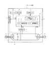
図14には従来のインバータ装置の構成例が示されている。この図14において、インバータ装置1に交流電源2が投入された状態では、内部の直流電源回路1aから制御部3に電源が供給され、制御部3内のワンチップCPU4(内蔵プログラム13)が稼動する。CPU4が稼動した状態では、例えば、EEPROMなどの読み書き可能な不揮発性メモリ5からインバータ装置1を運転するために必要なパターン設定データ(パラメータ)が、CPU4内の揮発性メモリ6(RAM)に読み出される。
FIG. 14 shows a configuration example of a conventional inverter device. In FIG. 14, when the
その後、端子台・通信手段などの外部入出力手段7やタッチパネル8からの入力によりインバータ装置1の運転開始指令が行われた場合に、CPU4は、直流電源回路1aの出力電圧を検出するように設けられた電圧検出手段9からの電圧データ(Vdc)に基づいて、運転可能な主回路直流電圧(P−N間電圧)が供給されていることを確認し、インバータ装置1が正常であれば、上記パターン運転データに基づいて誘導電動機10の可変速制御を行うというパターン運転をシーケンシャルに実行する。このパターン運転時には、運転中のパターン周波数の切換(パターン番号の切換)やそのパターンの運転経過時間やパターン繰り返し回数といったパターン制御データ(実際の運転進行状態などを示すデータ)が、揮発性メモリ6に逐次記憶されるものであり、当該パターン制御データに基づいて、パターン周波数の切換や各パターン周波数での運転時間の制御などが行われる。
Thereafter, the CPU 4 detects the output voltage of the DC power supply circuit 1a when an operation start command for the
上記誘導電動機10の可変速運転は、直流電源回路1aの出力をスイッチングするためのインバータ主回路11をPWM制御することにより行われるものであり、そのインバータ主回路11からの可変電圧・可変周波数出力により負荷である誘導電動機10の可変速運転が行われる。尚、インバータ主回路11は、IGBTなどのパワー素子をブリッジ接続した周知構成のものである。また、CPU4は、パラメータ設定や運転周波数のような運転データなどを表示手段12を通じて表示できる構成となっている。
The variable speed operation of the
例えば特許文献1に記載されたインバータ装置においては、運転条件を設定するための複数のパターン周波数とパターン運転時間といったパターン設定データを、読み書き可能な不揮発性メモリに対し予めパラメータデータとして記憶させる構成となっている。図14に示したインバータ装置1においても、CPU4(内蔵プログラム13)はパターン運転制御手段14を有し、パターン運転が選択された場合、同制御手段14は、図15の例に示すようにパラメータ1F〜パラメータ3Fのパターン周波数、パラメータ1T〜パラメータ3Tのパターン運転時間により、パラメータ設定通りのシーケンスに従った誘導電動機10の可変速運転(所謂パターン運転)を実現する。
For example, in the inverter device described in
このようなインバータ装置1によるパターン運転を有効活用したシステムの一つに、例えば繊維機械の精紡機が挙げられる。通常、精紡機においては、糸切れ防止(つまり生産性向上)のために巻き取り開始時は低速運転し、通常時は、糸の材質に応じた速度で高速運転することで稼働率を上げることが行われている。この場合、ある程度時間が経過して巻き取り量が増加したときには、そのままの巻き取り速度では巻き始め時と比較して張力が高くなって糸切れしやすくなるので中速運転状態とすることが行われる。つまり、低速→高速→中速(低速)といった速度差を設ける必要がある。
One example of a system that effectively utilizes such pattern operation by the
このため、従来では、精紡機の駆動源にインバータ装置が採用されるようになる前の段階では、2〜3パターン程度の速度差を機械的若しくは直流電動機の可変速制御により実現し、時間経過に応じて順次速度切換えを行う構成としていた。しかしながら、この構成では、メンテナンス性に劣ると共に、多様な速度パターンの設定が難しくなるなどの欠点が存在するため、近年では、メンテナンス性に優れた誘導電動機を高効率かつ容易に可変速できるといった理由から、インバータ装置を採用することが一般的になっており、さらに、図14のようなパターン運転制御手段14を備えたインバータ装置1を採用することにより、外部のシーケンサを不要にできるといったコストメリットを発生させることも行われている。
For this reason, conventionally, before the inverter device is adopted as the drive source of the spinning machine, a speed difference of about 2 to 3 patterns is realized by mechanical or variable speed control of a DC motor, and time elapses. The speed is sequentially switched according to the situation. However, in this configuration, there are drawbacks such as inferior maintainability and difficulty in setting various speed patterns. In recent years, the reason is that an induction motor with excellent maintainability can be easily changed with high efficiency. Therefore, it is common to adopt an inverter device, and further, by adopting the
また、インバータ装置採用のもう一つの理由は次の通りである。即ち、紡績工場においては、1台につき250〜400錘の巻き取り装置を備えた精紡機を数百台程度設置することにより生産ラインが構成される。この場合、糸の巻き取りが同時に終了すると、生産性(稼働率)が悪化することから、巻き取り装置の起動に一定間隔の時間差を設けて順次駆動することが行われている。インバータ装置のパターン運転時には、起動から停止までの運転時間を一定にすることが可能であり、従って外部からの指令によりインバータ装置の起動タイミングに間隔を設けるだけで、糸の巻き取りが同時に終了する事態を防止できることになり、以て生産性の向上を実現できるようになる。
従来の技術では、パターン運転制御手段14は、パターン運転中のパターン周波数の切換(パターン番号の切換)やそのパターンの運転経過時間やパターン繰り返し回数といったパターン制御データの管理には、頻繁なメモリアクセスや時間精度の観点からCPU4内部の揮発性メモリ6(RAM)やレジスタを用いて高速制御を行う構成としている。 In the prior art, the pattern operation control means 14 uses frequent memory access to manage pattern control data such as pattern frequency switching during pattern operation (pattern number switching), elapsed operation time of the pattern, and number of pattern repetitions. In addition, from the viewpoint of time accuracy, high-speed control is performed using a volatile memory 6 (RAM) or a register in the CPU 4.
このため、パターン運転途中に停電(瞬時停電を含む)などにより不足電圧が発生した場合には、制御部3に電源供給できずにCPU4がリセットされ、揮発性メモリ6上のパターン制御データが消失してしまう。つまり、図16の例に示すように復電後の運転開始時には、パターン運転を最初からやり直してしまうといった問題(所謂パターンリセット)が発生している。
For this reason, if an undervoltage occurs due to a power failure (including an instantaneous power failure) during pattern operation, the power is not supplied to the
特に、前述したインバータ装置1のパターン運転を用いた精紡機システムでは、停電などによりパターン制御データが消失しパターンリセットが発生すると、途中まで糸を巻き取った製品に対して、また最初から巻き始めるシーケンスとなり、糸の巻き取り過ぎによる製品不良や、巻き太りに起因した張力増加による糸切れといった問題が発生する。しかも、このように発生する不良品自体による損失に加え、ボビンヘ巻き取った糸をすべてほぐす作業のための人的損失などが二次的に発生するという問題もある。また、せっかく設定された起動タイミングの時間差がなくなるので、時間差を設けて再起動するという手間が発生し、生産性が悪化する。
In particular, in the spinning machine system using the pattern operation of the
要するに、停電に伴うパターンリセットが発生したときには莫大な損失を招くことになる。このため、従来では、外部にUPS(無停電電源装置)を設置し、インバータ装置1の制御部3(CPU4)の電源を復電まで保持するといった対策が採られているが、この対策では、UPSに搭載されたバッテリのメンテナンス(廃棄時の環境問題を含む)や設置に伴うコストの高騰といった別の問題が発生することになる。さらに、停電から復電までに長時間かかる場合には、UPS自体がダウンしてしまう場合があるので、結果として完全な対策を実施することはできない。また、日本国内においては電源事情が良いことから、上述のような損失が発生する可能性は比較的低いが、海外の発展途上国においては、電力供給不足により1日に2〜3回の停電(特に都市の郊外では、地域毎に割り当てた適当な時間帯毎に時分割で電力供給することが行われている)が発生するケースがあり、かなり深刻な問題となっている。
In short, when a pattern reset due to a power failure occurs, a huge loss is incurred. For this reason, conventionally, measures have been taken such as installing a UPS (uninterruptible power supply) outside and holding the power supply of the control unit 3 (CPU 4) of the
本発明は上記事情に鑑みてなされたもので、その目的は、揮発性メモリに記憶されたパターン設定データ並びに実際の運転進行状態などを示すパターン制御データに基づいて電動機の可変速制御を行うというパターン運転途中に、停電などにより不足電圧が発生した場合でも復電後において不足電圧発生前のパターン運転を継続できて、パターンリセットが発生する事態を確実に防止できるなどの効果を奏するインバータ装置を提供することにある。 The present invention has been made in view of the above circumstances, and its purpose is to perform variable speed control of an electric motor based on pattern setting data stored in a volatile memory and pattern control data indicating an actual driving progress state and the like. An inverter device that has the effect of being able to continue pattern operation before the occurrence of undervoltage after power recovery even if a shortage occurs due to a power failure during pattern operation, and to prevent the occurrence of pattern reset. It is to provide.
請求項1記載の発明は、前記目的を達成するために、予め設定されたパターン周波数、パターン運転時間などのパラメータより成るパターン設定データ並びにこのパターン設定データに基づいた実際の運転進行状態などを示すパターン制御データを記憶するための揮発性メモリを備え、当該パターン設定データ及びパターン制御データに基づいて電動機の可変速制御を行うというパターン運転をシーケンシャルに実行する制御部を備えたインバータ装置において、
電源電圧が設定レベル未満となった不足電圧状態を検出可能な電圧検出手段と、データ書き換え可能な不揮発性メモリとを備えた上で、
前記制御部に、前記パターン運転中に前記電圧検出手段が不足電圧検出状態となったときに、前記揮発性メモリ中の記憶データのうちパターン運転の続行に必要なデータを前記不揮発性メモリに記憶することで退避させ、その後に前記電圧検出手段による不足電圧検出状態が解除されたときに前記不揮発性メモリに記憶した退避データを読み出して前記揮発性メモリに復帰記憶させるパターン運転記憶手段を設け、当該パターン運転記憶手段を、不足電圧検出状態が解除された後において、出力周波数がパターン周波数に到達するまでの加速時間を通常使用する加速時間とは別に設定できる構成としたものである。
In order to achieve the above object, the invention according to claim 1 shows pattern setting data including parameters such as a preset pattern frequency and pattern operation time, and an actual operation progress state based on the pattern setting data. In an inverter device comprising a volatile memory for storing pattern control data, and having a control unit that sequentially executes pattern operation of performing variable speed control of the electric motor based on the pattern setting data and pattern control data.
With voltage detection means capable of detecting an undervoltage state where the power supply voltage has become less than a set level, and a nonvolatile memory capable of data rewriting,
When the voltage detecting means is in an undervoltage detection state during the pattern operation, the control unit stores data necessary for continuing the pattern operation in the nonvolatile memory among the stored data in the volatile memory. Providing a pattern operation storage means for reading the saved data stored in the non-volatile memory when the undervoltage detection state by the voltage detecting means is canceled after that, and returning to the volatile memory, The pattern operation storage means is configured such that the acceleration time until the output frequency reaches the pattern frequency after the undervoltage detection state is released can be set separately from the normal use acceleration time.
請求項2記載の発明は、前記目的を達成するために、予め設定されたパターン周波数、パターン運転時間などのパラメータより成るパターン設定データ並びにこのパターン設定データに基づいた実際の運転進行状態などを示すパターン制御データを記憶するための揮発性メモリを備え、当該パターン設定データ及びパターン制御データに基づいて電動機の可変速制御を行うというパターン運転をシーケンシャルに実行する制御部を備えたインバータ装置において、
電源電圧が設定レベル未満となった不足電圧状態を検出可能な電圧検出手段と、データ書き換え可能な不揮発性メモリとを備えた上で、
前記制御部に、前記パターン運転中に前記電圧検出手段が不足電圧検出状態となったときに、前記揮発性メモリ中の記憶データのうちパターン運転の続行に必要なデータを前記不揮発性メモリに記憶することで退避させ、その後に前記電圧検出手段による不足電圧検出状態が解除されたときに前記不揮発性メモリに記憶した退避データを読み出して前記揮発性メモリに復帰記憶させるパターン運転記憶手段を設け、前記パターン運転記憶手段を、不足電圧検出状態が解除された後において、前記揮発性メモリに復帰記憶されたデータにより示されるパターン周波数でのパターン運転を再開させる場合に、そのパターン周波数と前記電動機を当該パターン周波数まで加速するのに要する加速所要時間の積の1/2を算出すると共に、その算出値を上記パターン周波数で割った時間だけ、そのパターン周波数でのパターン運転時間を当初の設定時間より減少させる構成としたものである。
In order to achieve the above object, the invention according to claim 2 shows pattern setting data including parameters such as a preset pattern frequency and pattern operation time, and an actual operation progress state based on the pattern setting data. In an inverter device comprising a volatile memory for storing pattern control data, and having a control unit that sequentially executes pattern operation of performing variable speed control of the electric motor based on the pattern setting data and pattern control data.
With voltage detection means capable of detecting an undervoltage state where the power supply voltage has become less than a set level, and a nonvolatile memory capable of data rewriting,
When the voltage detecting means is in an undervoltage detection state during the pattern operation, the control unit stores data necessary for continuing the pattern operation in the nonvolatile memory among the stored data in the volatile memory. Providing a pattern operation storage means for reading the saved data stored in the non-volatile memory when the undervoltage detection state by the voltage detecting means is canceled after that, and returning to the volatile memory, When resuming the pattern operation at the pattern frequency indicated by the data restored and stored in the volatile memory after the undervoltage detection state is released, the pattern operation storage means Calculate 1/2 of the product of the required acceleration time required to accelerate to the pattern frequency, and the calculated value Only time divided by the pattern frequency is obtained by a structure for reducing the pattern operation time at the pattern frequency than originally set time.
請求項3記載の発明は、前記目的を達成するために、予め設定されたパターン周波数、パターン運転時間などのパラメータより成るパターン設定データ並びにこのパターン設定データに基づいた実際の運転進行状態などを示すパターン制御データを記憶するための揮発性メモリを備え、当該パターン設定データ及びパターン制御データに基づいて電動機の可変速制御を行うというパターン運転をシーケンシャルに実行する制御部を備えたインバータ装置において、
電源電圧が設定レベル未満となった不足電圧状態を検出可能な電圧検出手段と、データ書き換え可能な不揮発性メモリとを備えた上で、
前記制御部に、前記パターン運転中に前記電圧検出手段が不足電圧検出状態となったときに、前記揮発性メモリ中の記憶データのうちパターン運転の続行に必要なデータを前記不揮発性メモリに記憶することで退避させ、その後に前記電圧検出手段による不足電圧検出状態が解除されたときに前記不揮発性メモリに記憶した退避データを読み出して前記揮発性メモリに復帰記憶させるパターン運転記憶手段を設け、前記パターン運転記憶手段を、不足電圧検出時において前記揮発性メモリ中の記憶データを前記不揮発性メモリに対し正常に退避させられなかった場合に、その後に不足電圧検出状態が解除されたときにパターン記憶エラー信号を発生する構成としたものである。
In order to achieve the object, the invention described in
With voltage detection means capable of detecting an undervoltage state where the power supply voltage has become less than a set level, and a nonvolatile memory capable of data rewriting,
When the voltage detecting means is in an undervoltage detection state during the pattern operation, the control unit stores data necessary for continuing the pattern operation in the nonvolatile memory among the stored data in the volatile memory. Providing a pattern operation storage means for reading the saved data stored in the non-volatile memory when the undervoltage detection state by the voltage detecting means is subsequently released, and returning to the volatile memory. When the undervoltage detection state is canceled after the stored data in the volatile memory is not normally saved in the non-volatile memory when the undervoltage is detected, the pattern operation storage means The storage error signal is generated.
請求項4記載の発明は、前記目的を達成するために、予め設定されたパターン周波数、パターン運転時間などのパラメータより成るパターン設定データ並びにこのパターン設定データに基づいた実際の運転進行状態などを示すパターン制御データを記憶するための揮発性メモリを備え、当該パターン設定データ及びパターン制御データに基づいて電動機の可変速制御を行うというパターン運転をシーケンシャルに実行する制御部を備えたインバータ装置において、
電源電圧が設定レベル未満となった不足電圧状態を検出可能な電圧検出手段と、データ書き換え可能な不揮発性メモリとを備えた上で、
前記制御部に、前記パターン運転中に前記電圧検出手段が不足電圧検出状態となったときに、前記揮発性メモリ中の記憶データのうちパターン運転の続行に必要なデータを前記不揮発性メモリに記憶することで退避させ、その後に前記電圧検出手段による不足電圧検出状態が解除されたときに前記不揮発性メモリに記憶した退避データを読み出して前記揮発性メモリに復帰記憶させるパターン運転記憶手段を設け、前記パターン運転記憶手段を、外部からリセット要求が与えられていた場合に、不足電圧検出状態が解除された後に前記不揮発性メモリ中の退避データをリセットする構成としたものである。
In order to achieve the above object, the invention according to claim 4 shows pattern setting data including parameters such as a preset pattern frequency and pattern operation time, and an actual driving progress state based on the pattern setting data. In an inverter device comprising a volatile memory for storing pattern control data, and having a control unit that sequentially executes pattern operation of performing variable speed control of the electric motor based on the pattern setting data and pattern control data.
With voltage detection means capable of detecting an undervoltage state where the power supply voltage has become less than a set level, and a nonvolatile memory capable of data rewriting,
When the voltage detecting means is in an undervoltage detection state during the pattern operation, the control unit stores data necessary for continuing the pattern operation in the nonvolatile memory among the stored data in the volatile memory. Providing a pattern operation storage means for reading the saved data stored in the non-volatile memory when the undervoltage detection state by the voltage detecting means is canceled after that, and returning to the volatile memory, The pattern operation storage means is configured to reset saved data in the nonvolatile memory after the undervoltage detection state is released when a reset request is given from the outside.
請求項5記載の発明は、前記目的を達成するために、予め設定されたパターン周波数、パターン運転時間などのパラメータより成るパターン設定データ並びにこのパターン設定データに基づいた実際の運転進行状態などを示すパターン制御データを記憶するための揮発性メモリを備え、当該パターン設定データ及びパターン制御データに基づいて電動機の可変速制御を行うというパターン運転をシーケンシャルに実行する制御部を備えたインバータ装置において、
電源電圧が設定レベル未満となった不足電圧状態を検出可能な電圧検出手段と、データ書き換え可能な不揮発性メモリとを備えた上で、
前記制御部に、前記パターン運転中に前記電圧検出手段が不足電圧検出状態となったときに、前記揮発性メモリ中の記憶データのうちパターン運転の続行に必要なデータを前記不揮発性メモリに記憶することで退避させ、その後に前記電圧検出手段による不足電圧検出状態が解除されたときに前記不揮発性メモリに記憶した退避データを読み出して前記揮発性メモリに復帰記憶させるパターン運転記憶手段を設け、前記パターン運転記憶手段を、前記不揮発性メモリへの退避データの記憶更新回数をカウントし、そのカウント値が設定回数以上となったときにアラーム出力を行う構成としたものである。
In order to achieve the object, the invention according to
With voltage detection means capable of detecting an undervoltage state where the power supply voltage has become less than a set level, and a nonvolatile memory capable of data rewriting,
When the voltage detecting means is in an undervoltage detection state during the pattern operation, the control unit stores data necessary for continuing the pattern operation in the nonvolatile memory among the stored data in the volatile memory. Providing a pattern operation storage means for reading the saved data stored in the non-volatile memory when the undervoltage detection state by the voltage detecting means is canceled after that, and returning to the volatile memory, The pattern operation storage means is configured to count the number of times the stored data is stored and updated in the non-volatile memory, and to output an alarm when the count value exceeds the set number.
請求項6記載の発明は、前記目的を達成するために、予め設定されたパターン周波数、パターン運転時間などのパラメータより成るパターン設定データ並びにこのパターン設定データに基づいた実際の運転進行状態などを示すパターン制御データを記憶するための揮発性メモリを備え、当該パターン設定データ及びパターン制御データに基づいて電動機の可変速制御を行うというパターン運転をシーケンシャルに実行する制御部を備えたインバータ装置において、
電源電圧が設定レベル未満となった不足電圧状態を検出可能な電圧検出手段と、データ書き換え可能な不揮発性メモリとを備えた上で、
前記制御部に、前記パターン運転中に前記電圧検出手段が不足電圧検出状態となったときに、前記揮発性メモリ中の記憶データのうちパターン運転の続行に必要なデータを前記不揮発性メモリに記憶することで退避させ、その後に前記電圧検出手段による不足電圧検出状態が解除されたときに前記不揮発性メモリに記憶した退避データを読み出して前記揮発性メモリに復帰記憶させるパターン運転記憶手段を設け、前記パターン運転記憶手段を、不足電圧状態発生時点での出力周波数を記憶保持し、不足電圧検出状態が解除されたときに実際の出力周波数を上記のように保持された出力周波数まで高めた後に、退避データに基づいて不足電圧検出状態となる前のパターン運転を継続させる継続させる構成としたものである。
In order to achieve the above object, the invention according to
With voltage detection means capable of detecting an undervoltage state where the power supply voltage has become less than a set level, and a nonvolatile memory capable of data rewriting,
When the voltage detecting means is in an undervoltage detection state during the pattern operation, the control unit stores data necessary for continuing the pattern operation in the nonvolatile memory among the stored data in the volatile memory. Providing a pattern operation storage means for reading the saved data stored in the non-volatile memory when the undervoltage detection state by the voltage detecting means is canceled after that, and returning to the volatile memory, The pattern operation storage means stores and holds the output frequency at the time of occurrence of the undervoltage state, and after raising the actual output frequency to the output frequency held as described above when the undervoltage detection state is released, Based on the saved data, the pattern operation before the undervoltage detection state is continued to be continued.
請求項7記載の発明は、前記目的を達成するために、予め設定されたパターン周波数、パターン運転時間などのパラメータより成るパターン設定データ並びにこのパターン設定データに基づいた実際の運転進行状態などを示すパターン制御データを記憶するための揮発性メモリを備え、当該パターン設定データ及びパターン制御データに基づいて電動機の可変速制御を行うというパターン運転をシーケンシャルに実行する制御部を備えたインバータ装置において、
電源電圧が設定レベル未満となった不足電圧状態を検出可能な電圧検出手段と、データ書き換え可能な不揮発性メモリとを備えた上で、
前記制御部に、前記パターン運転中に前記電圧検出手段が不足電圧検出状態となったときに、前記揮発性メモリ中の記憶データのうちパターン運転の続行に必要なデータを前記不揮発性メモリに記憶することで退避させ、その後に前記電圧検出手段による不足電圧検出状態が解除されたときに前記不揮発性メモリに記憶した退避データを読み出して前記揮発性メモリに復帰記憶させるパターン運転記憶手段を設け、初回のパターン運転起動時のみ、運転開始指令の入力時点から当該パターン運転開始までの待ち時間を変更設定できる構成としたものである。
In order to achieve the above object, the invention according to
With voltage detection means capable of detecting an undervoltage state where the power supply voltage has become less than a set level, and a nonvolatile memory capable of data rewriting,
When the voltage detecting means is in an undervoltage detection state during the pattern operation, the control unit stores data necessary for continuing the pattern operation in the nonvolatile memory among the stored data in the volatile memory. Providing a pattern operation storage means for reading the saved data stored in the non-volatile memory when the undervoltage detection state by the voltage detecting means is canceled after that, and returning to the volatile memory, Only when the first pattern operation is started, the waiting time from the input of the operation start command to the start of the pattern operation can be changed and set.
請求項1記載の発明によれば、パターン運転途中に停電などによる不足電圧状態が発生したときには、揮発性メモリ中の記憶データのうちパターン運転の続行に必要なデータを不揮発性メモリに退避させることができ、その後の復電時に、不揮発性メモリに記憶した退避データを揮発性メモリヘ復帰させることができる。このため、パターンリセットが発生する事態を確実に防止できるようになり、不足電圧状態の発生前のパターン運転を継続(復帰)することを、UPS(無停電電源装置)を設置しなくてもインバータ装置単体で可能になるなどの効果が得られる。また、請求項1記載の発明の構成によれば、復電後の加減速時間を、通常使用する加速時間と別に設定でき、復電後の加速時間を通常時より可能な限り短縮して、パターン周波数までの到達を短縮すれば、復電後の加速により発生する制御誤差を縮小できるといった効果が得られる。 According to the first aspect of the present invention, when an undervoltage state due to a power failure or the like occurs during pattern operation, the data necessary for continuing the pattern operation among the stored data in the volatile memory is saved in the nonvolatile memory. The saved data stored in the nonvolatile memory can be restored to the volatile memory at the time of subsequent power recovery. For this reason, it is possible to reliably prevent the occurrence of pattern reset, and it is possible to continue (return) the pattern operation before the occurrence of the undervoltage state without using a UPS (uninterruptible power supply). Effects such as being possible with a single device can be obtained. In addition, according to the configuration of the first aspect of the invention, the acceleration / deceleration time after power recovery can be set separately from the normal acceleration time, and the acceleration time after power recovery can be shortened as much as possible from the normal time. If the arrival at the pattern frequency is shortened, an effect that the control error caused by the acceleration after the power recovery can be reduced can be obtained.
請求項2記載の発明によれば、前記請求項1記載の発明と同様に、不足電圧状態の発生前のパターン運転を継続(復帰)することを、UPSを設置しなくてもインバータ装置単体で可能になるなどの効果が得られる。また、請求項2記載の発明によれば、復電後の加速途中における電動機の回転量を補正できるようになり、例えば精紡機に用いる場合には、停電が発生したときでも糸巻量を同一にできるとなどの効果があり、この他、精紡機以外の位置決めなどのシステムに使用する場合にはその位置決め精度を高くできるなどの効果がある。
According to the second aspect of the present invention, as in the first aspect of the present invention, it is possible to continue (return) the pattern operation before the occurrence of the undervoltage state by using only the inverter device without installing a UPS. The effect that it becomes possible is acquired. Further, according to the invention described in
請求項3記載の発明によれば、前記請求項1記載の発明と同様に、不足電圧状態の発生前のパターン運転を継続(復帰)することを、UPSを設置しなくてもインバータ装置単体で可能になるなどの効果が得られる。また、請求項3記載の発明によれば、停電などによる不足電圧状態の発生時において、パターン運転の続行に必要なデータを不揮発性メモリに正しく退避できなかった場合に、パターン記憶エラーを発生させる作用があるから、記憶された退避データの信頼性を向上できるといった効果が得られる。 According to the third aspect of the present invention, as in the first aspect of the present invention, it is possible to continue (return) the pattern operation before the occurrence of the undervoltage state with a single inverter device without installing a UPS. The effect that it becomes possible is acquired. According to the third aspect of the present invention, when an undervoltage state due to a power failure or the like occurs, a pattern storage error is generated when data necessary for continuing the pattern operation cannot be properly saved in the nonvolatile memory. Since there is an effect, it is possible to improve the reliability of stored saved data.
請求項4記載の発明によれば、前記請求項1記載の発明と同様に、不足電圧状態の発生前のパターン運転を継続(復帰)することを、UPSを設置しなくてもインバータ装置単体で可能になるなどの効果が得られる。また、請求項4記載の発明によれば、復電後の運転開始前に記憶されたパターン制御データを選択的にリセットできるから、復電時において、「パターン運転を最初から行うのか?」或いは「停電前の続きから行うのか?」といった選択を、ユーザ側で簡単に行うことが可能になる。 According to the fourth aspect of the invention, as in the first aspect of the invention, it is possible to continue (return) the pattern operation before the occurrence of the undervoltage state without using the UPS. The effect that it becomes possible is acquired. According to the fourth aspect of the present invention, the pattern control data stored before the start of operation after power recovery can be selectively reset. Therefore, during power recovery, “Do you want to perform pattern operation from the beginning?” Or The user can easily select “Do you want to continue from before the power failure?”.
請求項5記載の発明によれば、前記請求項1記載の発明と同様に、不足電圧状態の発生前のパターン運転を継続(復帰)することを、UPSを設置しなくてもインバータ装置単体で可能になるなどの効果が得られる。また、請求項5記載の発明によれば、不揮発性メモリに対する退避データの記憶更新回数に係る保守情報を容易に得ることができる。 According to the fifth aspect of the invention, similar to the first aspect of the invention, the pattern operation before the occurrence of the undervoltage state is continued (returned) by the inverter unit alone without installing the UPS. The effect that it becomes possible is acquired. According to the fifth aspect of the present invention, it is possible to easily obtain maintenance information relating to the number of times the stored data is stored and updated in the nonvolatile memory.
請求項6記載の発明によれば、前記請求項1記載の発明と同様に、不足電圧状態の発生前のパターン運転を継続(復帰)することを、UPSを設置しなくてもインバータ装置単体で可能になるなどの効果が得られる。また、請求項6記載の発明によれば、加減速途中での不足電圧状態の発生時には、前回の運転周波数まで加速した後、不足電圧前のパターン運転を継続することになるので、不足電圧発生時点の状態への正確な復帰が可能となる。
According to the sixth aspect of the invention, similar to the first aspect of the invention, it is possible to continue (return) the pattern operation before the occurrence of the undervoltage state by using only the inverter device without installing a UPS. The effect that it becomes possible is acquired. According to the invention described in
請求項7記載の発明によれば、前記請求項1記載の発明と同様に、不足電圧状態の発生前のパターン運転を継続(復帰)することを、UPSを設置しなくてもインバータ装置単体で可能になるなどの効果が得られる。また、請求項7記載の発明によれば、パターン運転を行う場合において、初回起動時の待ち時間を予めパラメータなどで変更設定することが可能となって、初回起動時の時間差もインバータ装置単体で正確に設けることが可能となる。 According to the seventh aspect of the present invention, as in the first aspect of the present invention, it is possible to continue (reset) the pattern operation before the occurrence of the undervoltage state without using a UPS. The effect that it becomes possible is acquired. According to the seventh aspect of the present invention, when performing pattern operation, the waiting time at the first activation can be changed and set in advance by using a parameter or the like. It becomes possible to provide accurately.
以下、本発明の第1〜第7の実施形態について説明するに、まず、それら第1〜第7の実施形態の前提となる基本構成例について図1〜図4を参照しながら説明する。尚、インバータ装置の構成例を示す図1において、前記図14と同じ要素には同一符号を付すことにより説明を省略する。 Hereinafter, first to seventh embodiments of the present invention will be described. First, basic configuration examples that are the premise of the first to seventh embodiments will be described with reference to FIGS. 1 to 4. In FIG. 1 showing a configuration example of the inverter device, the same elements as those in FIG.
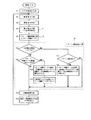
図1に示す構成例は、従来構成(図14)に対して、CPU4の内蔵プログラム13にパターン運転記憶手段15を追加したインバータ装置16を設けた構成に特徴を有するものであり、CPU4は、図2に示すフローチャートのような処理動作を行う。
The configuration example shown in FIG. 1 is characterized by a configuration in which an inverter device 16 in which pattern operation storage means 15 is added to the built-in
図2において、インバータ装置16の電源が投入されると、CPU初期化手段により、CPU4が初期化されると共に、ユーザがタッチパネル8や通信機能を備えた外部入出力手段7を用いて不揮発性メモリ5ヘ予め設定しておいた加減速時間、パターン周波数、パターン運転時間などのパラメータやプログラム上のデータより成るパターン設定データが揮発性メモリ6に読み込まれる(S1)。
In FIG. 2, when the power of the inverter device 16 is turned on, the CPU 4 is initialized by the CPU initialization unit, and the user uses the
異常検出手段による異常検出がない状態で、運転指令手段(外部入出力手段7やタッチパネル8)からの入力によりインバータ装置16の運転開始指令が行われた場合に、電圧検出手段9からの電圧データ(Vdc)に基づいて、運転可能な主回路直流電圧(P−N間電圧)が供給されていることを確認したときには、当該運転指令に基づいてインバータ装置16の運転を開始させるための処理を開始する(S2、S3、S4)。 The voltage data from the voltage detection means 9 when the operation start command for the inverter device 16 is given by the input from the operation command means (external input / output means 7 or touch panel 8) in a state where no abnormality is detected by the abnormality detection means. When it is confirmed that the operable main circuit DC voltage (P-N voltage) is supplied based on (Vdc), a process for starting the operation of the inverter device 16 based on the operation command is performed. Start (S2, S3, S4).
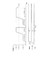
このとき、誘導電動機10に与える運転周波数は、通常はタッチパネル8によるパラメータ設定や、外部入出力手段7により決定されるが、パターン運転が選択された場合には、パターン運転制御手段14が、図3の例に示すようにパラメータ1F〜パラメータ3Fのパターン周波数、パラメータ1T〜パラメータ3Tのパターン運転時間により、パラメータ設定通りのシーケンスに従った誘導電動機10の可変速運転(所謂パターン運転)を実現する(S5)。
At this time, the operating frequency to be given to the
つまり、パターン運転制御手段14は、設定パラメータ若しくは外部入出力手段7によるパターン選択が有効な状態(図3において「パターン選択」が「ON」の期間)であれば、予め個別にパラメータとして設定記憶された例えば運転周波数f1(パラメータ1F)、運転周波数f2(パラメータ2F)、運転周波数f3(パラメータ3F)といった3種類の運転周波数データと、各運転周波数f1、f2、f3での運転時間データをそれぞれ示す運転時間t1(パラメータ1T)、運転時間t2(パラメータ2T)、運転時間t3(パラメータ3T)といった3種類の運転時間データとに基づいたパターン運転を行う。
In other words, the pattern
具体的には、運転周波数f1への加速完了後に運転時間t1の間は運転周波数f1で運転(パターン運転p1とする)し、運転時間t1の経過後には運転周波数f2への加速完了後に運転時間t2の間は運転周波数f2で運転(パターン運転p2とする)し、運転時間t2の経過後には運転周波数f3への減速完了後に運転時間t3の間は運転周波数f3で運転(パターン運転p3とする)するという自動シーケンス運転がパターン運転制御手段14により行われることで、図3に示すパターン運転を行う。 Specifically, after the acceleration to the operation frequency f1 is completed, the operation is performed at the operation frequency f1 during the operation time t1 (referred to as a pattern operation p1), and after the operation time t1 has elapsed, the operation time after the acceleration to the operation frequency f2 is completed. During t2, the operation is performed at the operation frequency f2 (referred to as the pattern operation p2), and after the operation time t2 has elapsed, after the deceleration to the operation frequency f3 is completed, the operation is performed at the operation frequency f3 during the operation time t3 (as the pattern operation p3) 3), the pattern operation shown in FIG. 3 is performed.
電圧検出手段9は電圧データ(Vdc)がパラメータなどで設定された一定以下の不足電圧を検出する機能(停電などの検出機能)があり、パターン運転記憶手段15は、この不足電圧の検出状態のチェック(S6)と、パターン運転中か否かのチェックを行う(S7)。各チェックにおいて、不足電圧状態とパターン運転中のAND条件が成立した場合には、パターン運転記憶手段15が、パターン制御データの退避処理(S8)を行う。この退避処理(S8)は、揮発性メモリ6(RAM)上で現在使用中のパターン周波数(パターン運転番号=前述のパターン運転p1〜p3)や、そのパターンでの運転経過時間(若しくはそのパターンでの残り運転時間)などのパターン制御データを、不揮発性メモリ5へ転送して記憶(退避)させる。
The voltage detection means 9 has a function (voltage blackout detection function) for detecting an undervoltage whose voltage data (Vdc) is less than a predetermined value set by a parameter or the like, and the pattern operation storage means 15 A check (S6) and a check of whether or not the pattern is being operated are performed (S7). In each check, when the undervoltage state and the AND condition during the pattern operation are satisfied, the pattern
パターン運転記憶手段15は、不足電圧を検出していない状態では、不揮発性メモリ5にパターン制御データが記憶(退避)されているかをチェックし(S9)、記憶されている場合に限り、記憶されたパターン制御データを揮発性メモリ6上に読み出して当該揮発性メモリ6に復帰させ(S10)、この後に不揮発性メモリ5に記憶されたパターン制御データをリセットする(S11)。尚、S10では、不揮発性メモリ5中のパターン設定データを揮発性メモリ6に再読み込みする動作も行う。
The pattern operation storage means 15 checks whether or not the pattern control data is stored (saved) in the
CPU4においては、揮発性メモリ6からインバータ装置16を運転するために必要なデータ(パラメータ)を読み出し、加減速演算手段がインバータ装置16による誘導電動機10の加減速時間などを演算し(S12)、演算・周波数出力手段がその演算結果及び上記読み出しデータを利用して誘導電動機10を駆動するための出力周波数などを演算すると共に、その演算結果に基づいてインバータ主回路11のためのPWM信号を作成して出力する(S13)。これにより、インバータ主回路11から可変電圧・可変周波数の交流出力が得られるようになり、誘導電動機10の可変速運転が、揮発性メモリ6に記憶されたパターン設定データ(パラメータ)及びパターン制御データに基づいて行われる。
In the CPU 4, data (parameters) necessary for operating the inverter device 16 is read from the
このような構成とした基本構成例によれば以下に述べるような効果が得られる。
従来のインバータ装置1を精紡機システムに採用した場合には、「発明が解決しようとする課題」の項で述べたように、停電(瞬時停電を含む)などにより、揮発性メモリ6中のパターン制御データが消失してパターンリセットが発生すると、途中まで巻き取った製品は不良品となってしまうといった事情(さらに、ボビンヘ巻き取った糸をすべてほぐす作業が必要になるといった事情)や、生産性向上のために予め設定されたインバータ装置1の起動タイミングの時間差がなくなるといった事情から、停電発生に伴い莫大な損失が発生する恐れがあり、また、外部にUPS(無停電電源装置)を設置することで、インバータ装置1の制御部3(CPU4)の電源を復電まで保持するといった対策が必要になるという問題点もあった。これに対して、基本構成例によるインバータ装置16を用いれば、図4に示すように、停電発生前のパターン運転を継続(復帰)することがインバータ装置16単体で可能となる。尚、図4は、停電発生した場合でも、運転時間t2(パラメータ2T)が停電発生しなかった場合(図3参照)と同一になる例を示している。このため、シーケンサやUPSなどの付帯設備がー切不要になるので、ユーザシステムの低コスト化/小形化を実現できると共に、データを長時間にわたって記憶保持できて信頼性が向上するといった効果を得ることができる。特に、電源事情が悪く1日に数回の停電が発生する発展途上国の精紡機システムに、基本構成例によるインバータ装置16を導入すれば、その効果が顕著になることはいうまでもない。
According to the basic configuration example having such a configuration, the following effects can be obtained.
When the
尚、不揮発性メモリ5としては、EEPROMに限らずフラッシュメモリなどを用いることができ、また、インバータ装置16の外部オプションとして設けることもできる。電圧検出手段9は、インバータ装置の一次側(入力側)に設けても良く、これに代えて不足電圧を示す外部信号入力をトリガとして不足電圧検出動作を行う手段を設けても良い。
Note that the
インバータ装置16の異常時や非常停止信号が発生した場合などに、揮発性メモリ6上のパターン制御データを不揮発性メモリ5へ一時的に退避させ、異常リセット後や非常停止信号のキャンセル後に元の状態へ復帰させる構成として実施しても良い。パターン運転記憶手段15の記憶データの選択を、外部入出力手段7やパラメータにより行えるように構成しても良い。
When the inverter device 16 is abnormal or when an emergency stop signal is generated, the pattern control data on the
また、上記基本構成例において、起動時に誘導電動機10の回転速度(周波数)を検出して、その回転速度から起動するという所謂スピードサーチ機能を併用したり、停電などにより電源が供給されない場合に誘導電動機10を回生状態とし、その電力を利用して運転継続することが可能な瞬停ノンストップ機能を併用することでより大きな効果が生まれることはいうまでもない。
In addition, in the above basic configuration example, when the rotation speed (frequency) of the
(第1の実施形態)
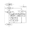
図5には、前記基本構成例に変更を加えた本発明の第1実施形態が示されており、以下これについて異なる部分のみ説明する。
本実施形態は、基本構成例における図2のフローチャート中のパターン運転記憶手段15の構成に対し、不揮発性メモリ5に記憶されたパターン制御データを揮発性メモリ6上に読み出して当該揮発性メモリ6に復帰させる処理(S10)を行う際にインバータ装置16が使用する加減速時間データを切換可能な機能を追加した点に特徴を有する。
(First embodiment)
FIG. 5 shows a first embodiment of the present invention in which the basic configuration example is modified, and only different parts will be described below.
In the present embodiment, pattern control data stored in the
具体的には、図5に示したように、パターン制御データの復帰(S10)、不揮発性メモリ5中のパターン制御データのリセット(S11)の後で、加減速時間データ変更要求のセットを作用させ(S14)、同要求の有無をチェックする(S15)。加減速時間データ変更要求がセットの場合、パターン周波数への到達チェックを行い(S16)、到達するまで変更加減速時間データ(ACC2:パラメータとして設定可能な加速時間2、dEC2:パラメータとして設定可能な減速時間2)のセットに作用し(S17)、到達した場合には、加減速データ変更要求をクリアし(S18)、通常加減速時間データ(ACC1:パラメータとして設定可能な加速時間1、dEC1:パラメータとして設定可能な減速時間1)のセットに作用する(S19)。加減速演算手段は、設定された加減速時間データを用いインバータ装置16の加減速時間を変化させる(S12)。
Specifically, as shown in FIG. 5, after the pattern control data is restored (S10) and the pattern control data in the
このように構成した本実施形態によれば、復電後の加減速時間(停止状態(0Hz)からパターン運転周波数までの加減速時間)を、通常使用する加減速時間データ(ACC1、dEC1)と別に設定でき、復電後の加減速時間データ(ACC2、dEC2)を通常時より可能な限り短縮して、パターン周波数までの到達時間を短縮すれば、復電後の加速により発生する制御誤差を縮小できるといった効果がある。また、本実施形態によるインバータ装置16を精紡機に用いた場合、復電後のパターン周波数が高く且つ既に糸がある程度巻き取られた状態時には、通常加減速を用いると起動直後に過剰な張力が発生するため糸切れ(ひいては生産性悪化)を引き起こすといった問題が発生するおそれがあるが、通常使用する加減速時間データ(ACC1、dEC1)より復電後の加減速時間データ(ACC2、dEC2)を長めに設定することで、このような糸切れを未然に防止して生産性の向上を図ることが可能となる。 According to the present embodiment configured as described above, the acceleration / deceleration time (acceleration / deceleration time from the stop state (0 Hz) to the pattern operation frequency) after power recovery and the normally used acceleration / deceleration time data (ACC1, dEC1) and If the acceleration / deceleration time data (ACC2, dEC2) after power recovery is shortened as much as possible from the normal time and the time to reach the pattern frequency is shortened, the control error caused by acceleration after power recovery can be set separately. There is an effect that it can be reduced. In addition, when the inverter device 16 according to the present embodiment is used in a spinning machine, when the pattern frequency after power recovery is high and the yarn has already been wound up to some extent, if normal acceleration / deceleration is used, excessive tension is applied immediately after startup. However, there is a possibility that the yarn breakage (and hence the productivity deterioration) may occur. However, the acceleration / deceleration time data (ACC2, dEC2) after power recovery from the normally used acceleration / deceleration time data (ACC1, dEC1) By setting the length longer, it is possible to prevent such yarn breakage and improve productivity.
尚、本実施形態において、復電後の加減速時間を、通常使用する加減速時間データ(ACC1、dEC1)に対する比率設定により決定する構成としても良い。また、精紡機に用いる場合、糸切れの防止といった効果を得るために、復帰時の加速パターンを直線とせず、起動直後並びにパターン速度到達直前の加減速をそれぞれ緩和した所謂S字加減速を用いた構成として実施しても良い。 In addition, in this embodiment, it is good also as a structure which determines the acceleration / deceleration time after a power recovery by the ratio setting with respect to the acceleration / deceleration time data (ACC1, dEC1) used normally. When used in a spinning machine, in order to obtain an effect such as prevention of yarn breakage, the so-called S-shaped acceleration / deceleration is used in which the acceleration pattern at the time of return is not a straight line, and acceleration / deceleration immediately after startup and immediately before reaching the pattern speed is alleviated You may implement as a structure which was.
(第2の実施形態)
図6及び図7には、前記基本構成例に変更を加えた本発明の第2の実施形態が示されており、以下これについて異なる部分のみ説明する。
本実施形態は、基本構成例における図2のフローチャート中のパターン運転記憶手段15の構成中に、パターン制御データ補正手段17を設けた点に特徴を有する。
具体的には、図6に示したように、パターン制御データの復帰(S10)、不揮発性メモリ5中のパターン制御データのリセット(S11)の後に、パターン制御データ補正手段17を作用させる(S20)。当該補正手段17は、図7に示すように、復電後の運転開始と同時に加速時間データと不揮発性メモリ5から復帰したパターン周波数の積の1/2(斜線帯部Aの面積)を算出すると共に、その算出値を当該パターン周波数で割ることにより、斜線帯部Aと同一面積となる斜線帯部A′に対応した成分の時間Δtを算出し、復帰後のパターン周波数でのパターン運転時間を、その時間Δtだけ当初の設定時間より減少させる。具体的には、算出した時間Δtを、不揮発性メモリ5から復帰した不足電圧前のパターン開始からの運転経過時間に加算して、揮発性メモリ6上の運転経過時間データを補正する(揮発性メモリ6上のデータが運転残り時間の場合は、Δt時間分だけ減少させる)。つまり、揮発性メモリ上の運転経過時間=不揮発性メモリ上の運転経過時間+Δt、または、揮発性メモリ上の運転残り時間=不揮発性メモリ上の運転残り時間−Δtとなる処理を行う。
(Second Embodiment)
6 and 7 show a second embodiment of the present invention in which a modification is made to the basic configuration example, and only different parts will be described below.
The present embodiment is characterized in that a pattern control
Specifically, as shown in FIG. 6, after the pattern control data is restored (S10) and the pattern control data in the
この実施形態によれば、復電後の加速(停止状態(0Hz)からパターン運転周波数までの加速)途中における誘導電動機10の回転量(図7斜線帯部A)を補正できるので、精紡機に用いる場合には、停電未発生時の糸巻量と同一にできるといった効果があり、特に、加速時間が遅く復電時の加速による糸巻量が無視できない場合に効果的になる。この他、精紡機以外の位置決めなどのシステム用途にも適用可能になり、この場合には位置決め精度を高め得るようになる。 According to this embodiment, the amount of rotation of the induction motor 10 (shaded area A in FIG. 7) during the acceleration after the power recovery (acceleration from the stop state (0 Hz) to the pattern operation frequency) can be corrected. When used, there is an effect that it can be made the same as the amount of bobbin winding when no power failure occurs, and it is particularly effective when the accelerating time is slow and the amount of bobbin winding due to acceleration during power recovery cannot be ignored. In addition, the present invention can be applied to system applications such as positioning other than the spinning machine. In this case, positioning accuracy can be improved.
(第3の実施形態)
図8には、前記基本構成例に変更を加えた本発明の第3の実施形態が示されており、以下これについて異なる部分のみ説明する。
本実施形態は、基本構成例における図2のフローチャート中のパターン運転記憶手段15の構成に対し、インバータ異常発生手段18を設けた点に特徴を有する。
具体的には、図8に示したように、パターン制御データの退避処理(S8)の後に、パターン制御データをすべて記憶したか否かをチェックし(S21)、記憶完了時には、パターン記憶完了データを不揮発性メモリ5にセットする(S22)。また、パターン制御データの復帰(S10)の前に、不揮発性メモリ5にパターン記憶完了データがセットされているか否かをチェックし(S23)、セットされていれば正常とみなし、パターン制御データの復帰(S10)、並びにパターン制御データのリセット(S11)を順次行った後に、不揮発性メモリ5に記憶されたパターン記憶完了データをリセットする(S24)。これに対して、S23でのチェックの結果、不揮発性メモリ5にパターン記憶完了データがセットされていなかったときには異常とみなし、この場合には、インバータ異常発生手段18を作用させてパターン記憶エラー信号を発生する(S25)。尚、このパターン記憶エラー信号発生時には表示手段12などで異常表示を行う。
(Third embodiment)
FIG. 8 shows a third embodiment of the present invention in which the basic configuration example is modified, and only different parts will be described below.
The present embodiment is characterized in that an inverter abnormality generating means 18 is provided with respect to the configuration of the pattern operation storage means 15 in the flowchart of FIG. 2 in the basic configuration example.
Specifically, as shown in FIG. 8, after the pattern control data saving process (S8), it is checked whether or not all the pattern control data has been stored (S21). Is set in the nonvolatile memory 5 (S22). Further, before the pattern control data is restored (S10), it is checked whether or not the pattern storage completion data is set in the nonvolatile memory 5 (S23). After returning (S10) and resetting the pattern control data (S11) sequentially, the pattern storage completion data stored in the
この実施形態によれば、以下に述べるような効果を奏する。即ち、揮発性メモリ6上のパターン制御データを不揮発性メモリ5に記憶(退避)するには、当該不揮発性メモリ5がEEPROMから成る場合、通常数十ミリ秒の時間が必要になる。このため、パターン制御データのデータ量が大きくなると、すべて記憶できない可能性がある。このような場合、復電後のパターン運転を完全に復元できず、パターン運転時間やパターン周波数が異なるなどして、所期の目的を達成できなくなるという問題が発生する。この場合、本実施形態によれば、パターン制御データがすべて記憶できなかったときには、復電後においてインバータ記憶エラー信号を発生して異常表示を行う構成となっているから、記憶されたパターン制御データの信頼性を向上できるといった効果がある。尚、インバータ記憶エラー信号のリセットは、インバータ装置における通常の異常リセット方法とは別に構成しても良い。
According to this embodiment, the following effects can be obtained. That is, in order to store (save) the pattern control data on the
(第4の実施形態)
図9には、前記基本構成例に変更を加えた本発明の第4の実施形態が示されており、以下これについて異なる部分のみ説明する。
本実施形態は、基本構成例における図2のフローチャート中のパターン運転記憶手段15の構成に対し、パターン制御データ初期化手段19を設けた点に特徴を有する。
具体的には、図9に示したように、パターン制御データの復帰(S10)の前に、外部から例えば外部入出力手段7やタッチパネル8を通じて入力されるパターン制御データのリセット要求の有無をチエックし(S26)、リセット要求がない場合はパターン制御データの復帰(S10)を行うが、リセット要求があった場合はパターン制御データ初期化手段19を作用させて、不揮発性メモリ5に記憶されたパターン制御データのリセット、つまりパターンリセットを行う(S27)。このパターン制御データ初期化手段19は、従来構成と同様に、復電後、パターン運転を最初から行えるように作用する。
(Fourth embodiment)
FIG. 9 shows a fourth embodiment of the present invention in which the basic configuration example is modified, and only different parts will be described below.
The present embodiment is characterized in that a pattern control
Specifically, as shown in FIG. 9, before the return of the pattern control data (S10), it is checked whether or not there is a reset request for the pattern control data inputted from the outside through, for example, the external input / output means 7 or the
このような本実施形態の構成によれば、記憶されたパターン制御データを必要に応じてリセットし、最初からパターン運転を行えるといった効果がある。例えば、システム側の都合により、復電時において、「パターン運転を最初から行うのか?」或いは「停電前の続きから行うのか?」といった選択を、ユーザ側で簡単に行うことが可能になる。つまり、本実施形態によるインバータ装置16を例えば精紡機に適用した場合、復電後の起動前に、ユーザ側で糸などの材料が不良となったと判断したときにはパターン制御データのリセット(パターン運転を最初から行う)、継続可能と判断した場合にパターン制御データの復帰(パターン運転を継続する)といった選択が可能になる。 According to such a configuration of the present embodiment, there is an effect that the stored pattern control data is reset as necessary, and the pattern operation can be performed from the beginning. For example, for the convenience of the system side, at the time of power recovery, the user can easily make a selection such as “Do you want to start pattern operation from the beginning?” Or “Do you want to continue from before the power failure?”. That is, when the inverter device 16 according to the present embodiment is applied to, for example, a spinning machine, the pattern control data is reset (pattern operation is performed when the user determines that the material such as yarn is defective before starting after power recovery. When starting from the beginning), it is possible to select the return of pattern control data (continuation of pattern operation) when it is determined that the operation can be continued.
(第5の実施形態)
図10には、前記基本構成例に変更を加えた本発明の第5の実施形態が示されており、以下これについて異なる部分のみ説明する。
本実施形態は、基本構成例における図2のフローチャート中のパターン運転記憶手段15の構成に対し、記憶更新回数カウント手段20を設け、そのカウント値が所定値以上となったときにアラーム出力するようにした点に特徴を有する。
(Fifth embodiment)
FIG. 10 shows a fifth embodiment of the present invention obtained by modifying the basic configuration example, and only different parts will be described below.
In the present embodiment, a storage update frequency count means 20 is provided for the configuration of the pattern operation storage means 15 in the flowchart of FIG. 2 in the basic configuration example, and an alarm is output when the count value exceeds a predetermined value. It is characterized by the points.
具体的には、図10に示したように、パターン制御データの退避処理(S8)の後に、記憶更新回数カウント手段20を作用させて、パターン制御データの記憶が行われる毎にカウント値(初期値は零)をインクリメントし、そのカウント値を記憶更新回数データとして不揮発性メモリ5に記憶する(S28)。また、加減速演算手段での誘導電動機10の加減速時間などの演算処理(S12)の前に、不揮発性メモリ5に記憶した記憶更新回数を、予めパラメータなどで設定された上限回数と比較し(S29)、記憶更新回数≧上限回数の場合に、表示手段12や外部入出力手段7を通じてアラーム出力を行い(S30)、この後に加減速時間演算処理(S12)へ移行する。また、記憶更新回数<上限回数の場合には、そのまま加減速時間演算処理(S12)へ移行する。
Specifically, as shown in FIG. 10, after the pattern control data saving process (S8), the storage update frequency count means 20 is operated so that each time the pattern control data is stored, the count value (initial The value is zero), and the count value is stored in the
この実施形態によれば、不揮発性メモリ5に対するパターン制御データの記憶更新回数に係る保守情報を容易に得ることができる。例えば、不揮発性メモリ5(たとえばEEPROM)の書き換え変更回数に寿命(制限)がある場合には、アラーム出力により当該不揮発性メモリ5の交換時期を確認できるといった効果がある。尚、記憶更新回数そのものを表示手段12により表示したり、外部入出力手段7により確認可能な構成としても、同等の効果を得られることはいうまでもない。
According to this embodiment, it is possible to easily obtain maintenance information related to the number of times of storing and updating pattern control data in the
(第6の実施形態)
図11には、前記基本構成例に変更を加えた本発明の第6の実施形態が示されており、以下これについて異なる部分のみ説明する。
本実施形態は、基本構成例における図2のフローチャート中のパターン運転記憶手段15の構成に対し、パターン制御データの退避(不足電圧検出)時に、そのときの運転周波数を前回運転周波数として不揮発性メモリに記憶し、パターン制御データの記憶復帰時に、前回運転周波数まで加速した後、パターン制御データヘ復帰させる構成とした点に特徴を有する。
(Sixth embodiment)
FIG. 11 shows a sixth embodiment of the present invention obtained by modifying the basic configuration example, and only different parts will be described below.
In the present embodiment, in contrast to the configuration of the pattern
具体的には、図11に示したように、パターン制御データの退避処理(S8)の前に、そのときの運転周波数を前回運転周波数とし不揮発性メモリ5に記憶する(S31)。また、不足電圧解除後においてパターン制御データの復帰(S10)の前に、記憶した前回運転周波数と現在運転周波数と比較し(S32)、不一致であれば、運転周波数の目標を前回運転周波数に書き換え(S33)、この後に加減速時間演算処理(S12)へ移行する。これにより、前回運転周波数まで加速されることになる。また、前回運転周波数と現在運転周波数とが一致すれば、そのまま加減速時間演算処理(S12)へ移行する。これにより、パターン制御データの復帰処理(S10)が行われ、不足電圧発生前のパターン運転が継続されることになる。
Specifically, as shown in FIG. 11, before the pattern control data saving process (S8), the current operation frequency is stored in the
前記基本構成例の構成の場合、例えばパターン運転p1からパターン運転p2ヘ移行する途中で不足電圧が検出された場合に、復電後のパターン運転周波数が、次のパターン運転p2の運転周波数f2にすぐに移行してしまうといった問題が発生することが予想されるが、本実施形態によれば、加減速途中に不足電圧状態が発生したときには、前回の運転周波数まで加速した後、不足電圧前のパターン運転を継続することになるので、不足電圧発生時点の状態への正確な復帰が可能となる。 In the case of the configuration of the basic configuration example, for example, when an undervoltage is detected during the transition from the pattern operation p1 to the pattern operation p2, the pattern operation frequency after power recovery is changed to the operation frequency f2 of the next pattern operation p2. However, according to the present embodiment, when an undervoltage state occurs during acceleration / deceleration, after accelerating to the previous operating frequency, Since the pattern operation is continued, it is possible to accurately return to the state at the time of occurrence of the undervoltage.
(第7の実施形態)
図12及び図13には、前記基本構成例に変更を加えた本発明の第7の実施形態が示されており、以下これについて異なる部分のみ説明する。
本実施形態は、基本構成例における図2のフローチャート中におけるパターン運転制御手段14によるパターン運転の実行(S5)の直前に、パターン運転起動待機手段21を追加した点に特徴を有する。
(Seventh embodiment)
FIGS. 12 and 13 show a seventh embodiment of the present invention in which a modification is made to the basic configuration example, and only different parts will be described below.
The present embodiment is characterized in that a pattern operation start
具体的には、図12に示したように、運転指令手段(外部入出力手段7やタッチパネル8)からの入力によりインバータ装置16の運転開始指令が行われると、パターン運転制御手段14によるパターン運転が行われるが、パターン運転起動待機手段21は、初回運転時のみ運転許可を、パラメータなどで設定された待ち時間分だけ運転禁止とする(S34)。ここで、初回運転時とは不揮発性メモリ5ヘ初回の運転か否かの情報記憶が行われていない状態を示し、初回運転時に“初回運転済み”の情報を不揮発性メモリ5に記憶する動作を自動的に行うものとする。尚、“初回運転済み”の情報は、ユーザ側においてパラメータなどにより消去できるものとする。
Specifically, as shown in FIG. 12, when an operation start command for the inverter device 16 is given by an input from the operation command means (external input / output means 7 or touch panel 8), the pattern operation by the pattern operation control means 14 is performed. However, the pattern operation start standby means 21 prohibits the operation only during the initial operation and prohibits the operation for the waiting time set by the parameter or the like (S34). Here, the time of the first operation indicates a state in which information is not stored in the
この実施形態によれば、以下に述べるような効果を奏する。即ち、例えば精紡機の場合、数百台で生産ラインが構成される関係上、各精紡機において糸の巻き取りが同時に終了すると、生産性(稼働率)が悪化することから、巻き取り装置の起動に一定間隔の時間差を設けて順次駆動させることが行われている。このような精紡機の駆動にインバータ装置16を用いた場合、そのパターン運転は、起動から停止までの運転時間は一定にすることは可能であるが、この時間差は外部で設定する必要がある。本実施形態によれば、図13に示すようなパターン運転を行う場合において、初回起動時の待ち時間を予めパラメータなどで変更設定することが可能となって、初回起動時の時間差もインバータ装置16単体で正確に設けることが可能となるから、精紡機を駆動する用途に適したものにできる。 According to this embodiment, the following effects can be obtained. That is, for example, in the case of a spinning machine, because the production line is composed of several hundred units, the productivity (operating rate) deteriorates when the winding of the yarn ends simultaneously in each spinning machine. It is performed to drive sequentially with a time interval of a certain interval in starting. When the inverter device 16 is used to drive such a spinning machine, the operation time from start to stop can be made constant in the pattern operation, but this time difference needs to be set externally. According to the present embodiment, when performing the pattern operation as shown in FIG. 13, the waiting time at the first activation can be changed and set in advance with parameters or the like, and the time difference at the first activation is also the inverter device 16. Since the single unit can be provided accurately, it can be made suitable for the purpose of driving the spinning machine.
3は制御部、4はCPU、5は不揮発性メモリ、6は揮発性メモリ、9は電圧検出手段、10は誘導電動機、11はインバータ主回路、14はパターン運転制御手段、15はパターン運転記憶手段、16はインバータ装置を示す。 3 is a control unit, 4 is a CPU, 5 is a nonvolatile memory, 6 is a volatile memory, 9 is a voltage detection means, 10 is an induction motor, 11 is an inverter main circuit, 14 is a pattern operation control means, and 15 is a pattern operation memory. Means 16 indicates an inverter device.
Claims (7)
電源電圧が設定レベル未満となった不足電圧状態を検出可能な電圧検出手段と、
データ書き換え可能な不揮発性メモリとを備え、
前記制御部には、前記パターン運転中に前記電圧検出手段が不足電圧検出状態となったときに、前記揮発性メモリ中の記憶データのうちパターン運転の続行に必要なデータを前記不揮発性メモリに記憶することで退避させ、その後に前記電圧検出手段による不足電圧検出状態が解除されたときに前記不揮発性メモリに記憶した退避データを読み出して前記揮発性メモリに復帰記憶させるパターン運転記憶手段が設けられ、
前記パターン運転記憶手段は、不足電圧検出状態が解除された後において、出力周波数がパターン周波数に到達するまでの加速時間を通常使用する加速時間とは別に設定できる構成とされていることを特徴とするインバータ装置。 A volatile memory is provided for storing pattern setting data including parameters such as a preset pattern frequency and pattern operation time, and pattern control data indicating an actual operation progress state based on the pattern setting data. In an inverter device including a control unit that sequentially executes pattern operation of performing variable speed control of an electric motor based on setting data and pattern control data,
Voltage detection means capable of detecting an undervoltage state in which the power supply voltage is less than a set level;
With data rewritable nonvolatile memory,
When the voltage detection means is in an undervoltage detection state during the pattern operation, the control unit stores data necessary for continuing the pattern operation in the nonvolatile memory among the stored data in the volatile memory. There is provided a pattern operation storage means for reading the saved data stored in the non-volatile memory and returning to the volatile memory when the undervoltage detection state by the voltage detecting means is canceled after that is saved. And
The pattern operation storage means is configured to be able to set an acceleration time until the output frequency reaches the pattern frequency after the undervoltage detection state is released, separately from the acceleration time for normal use. Inverter device.
電源電圧が設定レベル未満となった不足電圧状態を検出可能な電圧検出手段と、
データ書き換え可能な不揮発性メモリとを備え、
前記制御部には、前記パターン運転中に前記電圧検出手段が不足電圧検出状態となったときに、前記揮発性メモリ中の記憶データのうちパターン運転の続行に必要なデータを前記不揮発性メモリに記憶することで退避させ、その後に前記電圧検出手段による不足電圧検出状態が解除されたときに前記不揮発性メモリに記憶した退避データを読み出して前記揮発性メモリに復帰記憶させるパターン運転記憶手段が設けられ、
前記パターン運転記憶手段は、不足電圧検出状態が解除された後において、前記揮発性メモリに復帰記憶されたデータにより示されるパターン周波数でのパターン運転を再開させる場合に、そのパターン周波数と前記電動機を当該パターン周波数まで加速するのに要する加速所要時間の積の1/2を算出すると共に、その算出値を上記パターン周波数で割った時間だけ、そのパターン周波数でのパターン運転時間を当初の設定時間より減少させる構成とされていることを特徴とするインバータ装置。 A volatile memory is provided for storing pattern setting data including parameters such as a preset pattern frequency and pattern operation time, and pattern control data indicating an actual operation progress state based on the pattern setting data. In an inverter device including a control unit that sequentially executes pattern operation of performing variable speed control of an electric motor based on setting data and pattern control data,
Voltage detection means capable of detecting an undervoltage state in which the power supply voltage is less than a set level;
With data rewritable nonvolatile memory,
When the voltage detection means is in an undervoltage detection state during the pattern operation, the control unit stores data necessary for continuing the pattern operation in the nonvolatile memory among the stored data in the volatile memory. There is provided a pattern operation storage means for reading the saved data stored in the non-volatile memory and returning to the volatile memory when the undervoltage detection state by the voltage detecting means is canceled after that is saved. And
The pattern operation storage means, when resuming the pattern operation at the pattern frequency indicated by the data restored and stored in the volatile memory after the undervoltage detection state is released, Calculate 1/2 of the product of the required acceleration time required to accelerate to the pattern frequency, and calculate the pattern operation time at the pattern frequency from the initial set time by dividing the calculated value by the pattern frequency. An inverter device characterized by being configured to decrease.
電源電圧が設定レベル未満となった不足電圧状態を検出可能な電圧検出手段と、
データ書き換え可能な不揮発性メモリとを備え、
前記制御部には、前記パターン運転中に前記電圧検出手段が不足電圧検出状態となったときに、前記揮発性メモリ中の記憶データのうちパターン運転の続行に必要なデータを前記不揮発性メモリに記憶することで退避させ、その後に前記電圧検出手段による不足電圧検出状態が解除されたときに前記不揮発性メモリに記憶した退避データを読み出して前記揮発性メモリに復帰記憶させるパターン運転記憶手段が設けられ、
前記パターン運転記憶手段は、不足電圧検出時において前記揮発性メモリ中の記憶データを前記不揮発性メモリに対し正常に退避させられなかった場合に、その後に不足電圧検出状態が解除されたときにパターン記憶エラー信号を発生する構成とされていることを特徴とするインバータ装置。 A volatile memory is provided for storing pattern setting data including parameters such as a preset pattern frequency and pattern operation time, and pattern control data indicating an actual operation progress state based on the pattern setting data. In an inverter device including a control unit that sequentially executes pattern operation of performing variable speed control of an electric motor based on setting data and pattern control data,
Voltage detection means capable of detecting an undervoltage state in which the power supply voltage is less than a set level;
With data rewritable nonvolatile memory,
When the voltage detection means is in an undervoltage detection state during the pattern operation, the control unit stores data necessary for continuing the pattern operation in the nonvolatile memory among the stored data in the volatile memory. There is provided a pattern operation storage means for reading the saved data stored in the non-volatile memory and returning to the volatile memory when the undervoltage detection state by the voltage detecting means is canceled after that is saved. And
When the undervoltage detection state is canceled after the stored data in the volatile memory is not normally saved in the nonvolatile memory when the undervoltage is detected, the pattern operation storage means An inverter device characterized by generating a storage error signal.
電源電圧が設定レベル未満となった不足電圧状態を検出可能な電圧検出手段と、
データ書き換え可能な不揮発性メモリとを備え、
前記制御部には、前記パターン運転中に前記電圧検出手段が不足電圧検出状態となったときに、前記揮発性メモリ中の記憶データのうちパターン運転の続行に必要なデータを前記不揮発性メモリに記憶することで退避させ、その後に前記電圧検出手段による不足電圧検出状態が解除されたときに前記不揮発性メモリに記憶した退避データを読み出して前記揮発性メモリに復帰記憶させるパターン運転記憶手段が設けられ、
前記パターン運転記憶手段は、外部からリセット要求が与えられていた場合に、不足電圧検出状態が解除された後に前記不揮発性メモリ中の退避データをリセットする構成とされていることを特徴とするインバータ装置。 A volatile memory is provided for storing pattern setting data including parameters such as a preset pattern frequency and pattern operation time, and pattern control data indicating an actual operation progress state based on the pattern setting data. In an inverter device including a control unit that sequentially executes pattern operation of performing variable speed control of an electric motor based on setting data and pattern control data,
Voltage detection means capable of detecting an undervoltage state in which the power supply voltage is less than a set level;
With data rewritable nonvolatile memory,
When the voltage detection means is in an undervoltage detection state during the pattern operation, the control unit stores data necessary for continuing the pattern operation in the nonvolatile memory among the stored data in the volatile memory. There is provided a pattern operation storage means for reading the saved data stored in the non-volatile memory and returning to the volatile memory when the undervoltage detection state by the voltage detecting means is canceled after that is saved. And
The pattern operation storage means is configured to reset saved data in the non-volatile memory after an undervoltage detection state is canceled when a reset request is given from the outside. apparatus.
電源電圧が設定レベル未満となった不足電圧状態を検出可能な電圧検出手段と、
データ書き換え可能な不揮発性メモリとを備え、
前記制御部には、前記パターン運転中に前記電圧検出手段が不足電圧検出状態となったときに、前記揮発性メモリ中の記憶データのうちパターン運転の続行に必要なデータを前記不揮発性メモリに記憶することで退避させ、その後に前記電圧検出手段による不足電圧検出状態が解除されたときに前記不揮発性メモリに記憶した退避データを読み出して前記揮発性メモリに復帰記憶させるパターン運転記憶手段が設けられ、
前記パターン運転記憶手段は、前記不揮発性メモリへの退避データの記憶更新回数をカウントし、そのカウント値が設定回数以上となったときにアラーム出力を行う構成とされていることを特徴とするインバータ装置。 A volatile memory is provided for storing pattern setting data including parameters such as a preset pattern frequency and pattern operation time, and pattern control data indicating an actual operation progress state based on the pattern setting data. In an inverter device including a control unit that sequentially executes pattern operation of performing variable speed control of an electric motor based on setting data and pattern control data,
Voltage detection means capable of detecting an undervoltage state in which the power supply voltage is less than a set level;
With data rewritable nonvolatile memory,
When the voltage detection means is in an undervoltage detection state during the pattern operation, the control unit stores data necessary for continuing the pattern operation in the nonvolatile memory among the stored data in the volatile memory. There is provided a pattern operation storage means for reading the saved data stored in the non-volatile memory and returning to the volatile memory when the undervoltage detection state by the voltage detecting means is canceled after that is saved. And
The pattern operation storage means is configured to count the number of times the stored data is stored and updated in the nonvolatile memory, and to output an alarm when the count value is equal to or greater than the set number of times. apparatus.
電源電圧が設定レベル未満となった不足電圧状態を検出可能な電圧検出手段と、
データ書き換え可能な不揮発性メモリとを備え、
前記制御部には、前記パターン運転中に前記電圧検出手段が不足電圧検出状態となったときに、前記揮発性メモリ中の記憶データのうちパターン運転の続行に必要なデータを前記不揮発性メモリに記憶することで退避させ、その後に前記電圧検出手段による不足電圧検出状態が解除されたときに前記不揮発性メモリに記憶した退避データを読み出して前記揮発性メモリに復帰記憶させるパターン運転記憶手段が設けられ、
前記パターン運転記憶手段は、不足電圧状態発生時点での出力周波数を記憶保持し、不足電圧検出状態が解除されたときに実際の出力周波数を上記のように保持された出力周波数まで高めた後に、退避データに基づいて不足電圧検出状態となる前のパターン運転を継続させる構成とされていることを特徴とするインバータ装置。 A volatile memory is provided for storing pattern setting data including parameters such as a preset pattern frequency and pattern operation time, and pattern control data indicating an actual operation progress state based on the pattern setting data. In an inverter device including a control unit that sequentially executes pattern operation of performing variable speed control of an electric motor based on setting data and pattern control data,
Voltage detection means capable of detecting an undervoltage state in which the power supply voltage is less than a set level;
With data rewritable nonvolatile memory,
When the voltage detection means is in an undervoltage detection state during the pattern operation, the control unit stores data necessary for continuing the pattern operation in the nonvolatile memory among the stored data in the volatile memory. There is provided a pattern operation storage means for reading the saved data stored in the non-volatile memory and returning to the volatile memory when the undervoltage detection state by the voltage detecting means is canceled after that is saved. And
The pattern operation storage means stores and holds the output frequency at the time of occurrence of the undervoltage state, and after raising the actual output frequency to the output frequency held as described above when the undervoltage detection state is released, An inverter device characterized by being configured to continue the pattern operation before entering the undervoltage detection state based on the saved data.
電源電圧が設定レベル未満となった不足電圧状態を検出可能な電圧検出手段と、
データ書き換え可能な不揮発性メモリとを備え、
前記制御部には、前記パターン運転中に前記電圧検出手段が不足電圧検出状態となったときに、前記揮発性メモリ中の記憶データのうちパターン運転の続行に必要なデータを前記不揮発性メモリに記憶することで退避させ、その後に前記電圧検出手段による不足電圧検出状態が解除されたときに前記不揮発性メモリに記憶した退避データを読み出して前記揮発性メモリに復帰記憶させるパターン運転記憶手段が設けられ、
初回のパターン運転起動時のみ、運転開始指令の入力時点から当該パターン運転開始までの待ち時間を変更設定できるように構成されていることを特徴とするインバータ装置。
A volatile memory is provided for storing pattern setting data including parameters such as a preset pattern frequency and pattern operation time, and pattern control data indicating an actual operation progress state based on the pattern setting data. In an inverter device including a control unit that sequentially executes pattern operation of performing variable speed control of an electric motor based on setting data and pattern control data,
Voltage detection means capable of detecting an undervoltage state in which the power supply voltage is less than a set level;
With data rewritable nonvolatile memory,
When the voltage detection means is in an undervoltage detection state during the pattern operation, the control unit stores data necessary for continuing the pattern operation in the nonvolatile memory among the stored data in the volatile memory. There is provided a pattern operation storage means for reading the saved data stored in the non-volatile memory and returning to the volatile memory when the undervoltage detection state by the voltage detecting means is canceled after that is saved. And
An inverter device configured to be able to change and set a waiting time from the time when an operation start command is input to the start of the pattern operation only when the first pattern operation is started.
Priority Applications (1)
| Application Number | Priority Date | Filing Date | Title |
|---|---|---|---|
| JP2005155702A JP2005295797A (en) | 2005-05-27 | 2005-05-27 | Inverter device |
Applications Claiming Priority (1)
| Application Number | Priority Date | Filing Date | Title |
|---|---|---|---|
| JP2005155702A JP2005295797A (en) | 2005-05-27 | 2005-05-27 | Inverter device |
Related Parent Applications (1)
| Application Number | Title | Priority Date | Filing Date |
|---|---|---|---|
| JP2000078054A Division JP2001268988A (en) | 2000-03-21 | 2000-03-21 | Inverter device |
Publications (1)
| Publication Number | Publication Date |
|---|---|
| JP2005295797A true JP2005295797A (en) | 2005-10-20 |
Family
ID=35328097
Family Applications (1)
| Application Number | Title | Priority Date | Filing Date |
|---|---|---|---|
| JP2005155702A Pending JP2005295797A (en) | 2005-05-27 | 2005-05-27 | Inverter device |
Country Status (1)
| Country | Link |
|---|---|
| JP (1) | JP2005295797A (en) |
Cited By (2)
| Publication number | Priority date | Publication date | Assignee | Title |
|---|---|---|---|---|
| KR101840510B1 (en) * | 2014-05-08 | 2018-03-20 | 엘에스산전 주식회사 | Apparatus and method for processing motor status data of inverter system |
| JP2018071890A (en) * | 2016-10-31 | 2018-05-10 | 株式会社不二工機 | Motor-driven valve control device and motor-driven valve device with the same |
-
2005
- 2005-05-27 JP JP2005155702A patent/JP2005295797A/en active Pending
Cited By (2)
| Publication number | Priority date | Publication date | Assignee | Title |
|---|---|---|---|---|
| KR101840510B1 (en) * | 2014-05-08 | 2018-03-20 | 엘에스산전 주식회사 | Apparatus and method for processing motor status data of inverter system |
| JP2018071890A (en) * | 2016-10-31 | 2018-05-10 | 株式会社不二工機 | Motor-driven valve control device and motor-driven valve device with the same |
Similar Documents
| Publication | Publication Date | Title |
|---|---|---|
| CN102033790B (en) | Method and device for upgrading embedded-type system BOOTROM | |
| US20030009701A1 (en) | Computer system and computer-readable recording medium | |
| JPH11299968A (en) | Pachinko machine | |
| US7977909B2 (en) | Device and method of driving stepping motor of analog electronic clock | |
| JP2001268988A (en) | Inverter device | |
| JP2005295797A (en) | Inverter device | |
| JP4279593B2 (en) | Elevator control device | |
| TWI847405B (en) | Method and system of swapping code execution | |
| CN112925548B (en) | Online program update method | |
| CN114490185A (en) | FPGA system parameter backup method | |
| JP5663821B2 (en) | Emergency generator control device and control method | |
| JP2009064285A (en) | Projection display | |
| CN114576810B (en) | Air conditioner control method and device, air conditioner and storage medium | |
| WO2013125164A1 (en) | Conversion device, control device, control method, and power distribution system | |
| CN107229495A (en) | A kind of system and method for preventing EMS remote upgrade from failing | |
| CN113409853A (en) | Method, device, storage medium and terminal for reducing probability of reading error after power failure | |
| CN111089411B (en) | Operation control device, electrical equipment and operation control method thereof | |
| JP2004318763A (en) | Job network management system and program | |
| CN119512828B (en) | Data synchronization method for electronic equipment, power supply circuit, electronic equipment and computer program product | |
| JPS6367617A (en) | Battery support system at service interruption | |
| CN119440640A (en) | Method, device and related product for controlling device startup | |
| CN111263232B (en) | Background OTA (over the air) upgrading implementation method and system based on digital set top box | |
| JP4900748B2 (en) | Portable communication device with automatic operation maintenance system and method for maintaining such device in operation | |
| JP7067152B2 (en) | Power conditioner | |
| JP2002157143A (en) | Debug support system for integrated circuit test program |
Legal Events
| Date | Code | Title | Description |
|---|---|---|---|
| A521 | Written amendment |
Free format text: JAPANESE INTERMEDIATE CODE: A523 Effective date: 20050818 |
|
| A131 | Notification of reasons for refusal |
Free format text: JAPANESE INTERMEDIATE CODE: A131 Effective date: 20080513 |
|
| A521 | Written amendment |
Free format text: JAPANESE INTERMEDIATE CODE: A523 Effective date: 20080714 |
|
| A02 | Decision of refusal |
Free format text: JAPANESE INTERMEDIATE CODE: A02 Effective date: 20090120 |