JP2005295783A - Harmonic entrainment prevention device, reactor device, and phase advance capacitor device - Google Patents
Harmonic entrainment prevention device, reactor device, and phase advance capacitor device Download PDFInfo
- Publication number
- JP2005295783A JP2005295783A JP2004251649A JP2004251649A JP2005295783A JP 2005295783 A JP2005295783 A JP 2005295783A JP 2004251649 A JP2004251649 A JP 2004251649A JP 2004251649 A JP2004251649 A JP 2004251649A JP 2005295783 A JP2005295783 A JP 2005295783A
- Authority
- JP
- Japan
- Prior art keywords
- reactor
- phase advance
- harmonic
- advance capacitor
- constant voltage
- Prior art date
- Legal status (The legal status is an assumption and is not a legal conclusion. Google has not performed a legal analysis and makes no representation as to the accuracy of the status listed.)
- Granted
Links
Images


Classifications
-
- Y—GENERAL TAGGING OF NEW TECHNOLOGICAL DEVELOPMENTS; GENERAL TAGGING OF CROSS-SECTIONAL TECHNOLOGIES SPANNING OVER SEVERAL SECTIONS OF THE IPC; TECHNICAL SUBJECTS COVERED BY FORMER USPC CROSS-REFERENCE ART COLLECTIONS [XRACs] AND DIGESTS
- Y02—TECHNOLOGIES OR APPLICATIONS FOR MITIGATION OR ADAPTATION AGAINST CLIMATE CHANGE
- Y02E—REDUCTION OF GREENHOUSE GAS [GHG] EMISSIONS, RELATED TO ENERGY GENERATION, TRANSMISSION OR DISTRIBUTION
- Y02E40/00—Technologies for an efficient electrical power generation, transmission or distribution
- Y02E40/30—Reactive power compensation
-
- Y—GENERAL TAGGING OF NEW TECHNOLOGICAL DEVELOPMENTS; GENERAL TAGGING OF CROSS-SECTIONAL TECHNOLOGIES SPANNING OVER SEVERAL SECTIONS OF THE IPC; TECHNICAL SUBJECTS COVERED BY FORMER USPC CROSS-REFERENCE ART COLLECTIONS [XRACs] AND DIGESTS
- Y02—TECHNOLOGIES OR APPLICATIONS FOR MITIGATION OR ADAPTATION AGAINST CLIMATE CHANGE
- Y02E—REDUCTION OF GREENHOUSE GAS [GHG] EMISSIONS, RELATED TO ENERGY GENERATION, TRANSMISSION OR DISTRIBUTION
- Y02E40/00—Technologies for an efficient electrical power generation, transmission or distribution
- Y02E40/40—Arrangements for reducing harmonics
Landscapes
- Emergency Protection Circuit Devices (AREA)
- Supply And Distribution Of Alternating Current (AREA)
- Control Of Electrical Variables (AREA)
Abstract
【課題】電力系統に挿入される進相コンデンサとその直列リアクトルとにおける鉄共振の一種である高調波引き込み現象を防止する。
【解決手段】進相コンデンサ装置10は、進相コンデンサ11と、進相コンデンサ11に電気的に接続された直列リアクトル12とを備えている。高調波引き込み現象防止装置20は、進相コンデンサ11に直列に、かつ、直列リアクトル12に並列に接続されている。高調波引き込み現象防止装置20は、ギャップ素子21と、バリスタ素子22と、抵抗値が50Ω〜2kΩの範囲内にある抵抗素子23とを直列に接続して構成されている。
【選択図】図2Harmonic pull-in phenomenon that is a kind of iron resonance in a phase advance capacitor and a series reactor inserted in a power system is prevented.
A phase advance capacitor device 10 includes a phase advance capacitor 11 and a series reactor 12 electrically connected to the phase advance capacitor 11. The harmonic entrainment prevention device 20 is connected in series with the phase advance capacitor 11 and in parallel with the series reactor 12. The harmonic entrainment prevention device 20 is configured by connecting a gap element 21, a varistor element 22, and a resistance element 23 having a resistance value in the range of 50Ω to 2 kΩ in series.
[Selection] Figure 2
Description
本発明は、高調波引き込み現象防止装置、および、それを用いたリアクトル装置、さらには進相コンデンサ装置に関する。 The present invention relates to a harmonic entrainment prevention device, a reactor device using the same, and a phase advance capacitor device.
近年、インバータ方式の電源装置を備えた機器の普及に伴い、これら機器から電力系統に流れ出た高調波が受電設備等に種々の障害を生じさせている。とりわけ被害の多い設備は、進相コンデンサ装置における直列リアクトルである。 In recent years, with the widespread use of devices equipped with inverter-type power supply devices, harmonics that have flowed out of these devices to the power system have caused various obstacles in the power receiving facilities and the like. A particularly damaging facility is a series reactor in a phase advance capacitor device.
そして、直列リアクトルに焼損等の損傷が発生する事故の多くが、進相コンデンサ装置を電力系統に接続したときの突入電流によって、直列リアクトルにおいて鉄心磁気飽和が生じてそのリアクタンスが低下し、第5調波などの高調波で共振状態となって、大きな電流が継続して流れることによって発生している。以下、この現象を高調波引き込み現象と称する。 Many of the accidents in which the series reactor is damaged such as burnout are caused by the inrush current when the phase advance capacitor device is connected to the electric power system, the core magnetic saturation occurs in the series reactor, and the reactance decreases. Resonance occurs at higher harmonics such as harmonics, and a large current continues to flow. Hereinafter, this phenomenon is referred to as a harmonic drawing phenomenon.
このような現象の発生を防止するための方法として、直列リアクトルに、電源投入時にこの直列リアクトル端子間に生じる電圧で導通するバリスタを並列に接続しておくことで、進相コンデンサへの突入電流の大部分を、バリスタを通して分流させる方法が提案されている(たとえば、特許文献1)。さらには、抵抗値が直列リアクトルのリアクタンスよりも十分に低く設定された限流抵抗器を、このバリスタに直列に接続してもよいことが提案されている。
この方法によれば、バリスタ、もしくはバリスタおよび限流抵抗器に、電源投入時の突入電流の大半をバイパスさせることによって、直列リアクトルに流れる電流をその鉄心が磁気飽和を生じない大きさとすることから、直列リアクトルの突入電流抑制機能がいちじるしく損なわれることになる。このため、電源投入時には電源系統に電圧変動を生じさせるという好ましくない現象が発生する。 According to this method, the varistor, or the varistor and the current limiting resistor, bypasses most of the inrush current when the power is turned on, so that the current flowing through the series reactor is made large enough that the iron core does not cause magnetic saturation. The inrush current suppression function of the series reactor will be severely impaired. For this reason, an undesired phenomenon of causing a voltage fluctuation in the power supply system occurs when the power is turned on.
本発明は、進相コンデンサ装置の直列リアクトルがもつ突入電流抑制作用を損なうことがなく、電源系統の電圧動揺を軽減し、また、直列リアクトルと進相コンデンサとで鉄共振現象が発生したときには、それをきわめて短期間に終息させることができる高調波引き込み現象防止装置およびこれを配備した進相コンデンサ装置を提供しようとするものである。 The present invention does not impair the inrush current suppression action of the series reactor of the phase advance capacitor device, reduces the voltage fluctuation of the power supply system, and when an iron resonance phenomenon occurs between the series reactor and the phase advance capacitor, It is an object of the present invention to provide a harmonic entrainment prevention device capable of terminating it in a very short time and a phase advance capacitor device provided with the same.
本発明の高調波引き込み現象防止装置は、進相コンデンサとリアクトルとを直列接続した進相コンデンサ装置に、前記進相コンデンサとは直列に、かつ、前記リアクトルとは並列に接続される高調波引き込み現象防止装置であって、定電圧スイッチング部と、この定電圧スイッチング部に直列に接続された抵抗部とを備え、定電圧スイッチング部の導通開始電圧がリアクトルに正常時に印加される電圧より高く、また、抵抗部が50Ω〜2kΩの範囲内の抵抗値としたものである。 The harmonic entrainment phenomenon prevention device of the present invention is a phase advance capacitor device in which a phase advance capacitor and a reactor are connected in series, and the phase advance capacitor is connected in series and in parallel with the reactor. A phenomenon prevention device comprising a constant voltage switching unit and a resistance unit connected in series to the constant voltage switching unit, the conduction start voltage of the constant voltage switching unit is higher than the voltage applied to the reactor at normal time, The resistance portion has a resistance value in a range of 50Ω to 2 kΩ.
この装置は、抵抗部がこれまで提案された装置に比べて高い抵抗値をもつことから、進相コンデンサ装置の電源系統投入時の突入電流に対するリアクトルの抑制効果が損なわれることがなく、電源系統の電圧動揺をいちじるしく低減することができる。また、この突入電流によりリアクトルの鉄心が磁気飽和し、進相コンデンサとの間で共振が発生しても、共振電圧で定電圧スイッチング部が導通し進相コンデンサからの過電流の一部分が高調波引き込み現象防止装置を流れる。この過電流のバイパスによって、進相コンデンサ・リアクトル間の共振がきわめて短期間に減衰して、進相コンデンサやリアクトルに大電流が長時間にわたって繰り返し流れるのが阻止される。 In this device, since the resistance portion has a higher resistance value than the devices proposed so far, the effect of suppressing the reactor against the inrush current at the time of turning on the power system of the phase advance capacitor device is not impaired, and the power system The voltage fluctuation can be remarkably reduced. In addition, even if the reactor core is magnetically saturated due to this inrush current and resonance occurs with the phase advance capacitor, the constant voltage switching unit is conducted by the resonance voltage, and a part of the overcurrent from the phase advance capacitor is harmonic. Flows through a pull-in prevention device. By this overcurrent bypass, resonance between the phase advance capacitor and the reactor is attenuated in a very short time, and a large current is prevented from repeatedly flowing through the phase advance capacitor and the reactor for a long time.
電圧スイッチング部としては、バリスタ素子,ギャップ素子,双方向性サイリスタ素子およびこれらの組み合わせのいずれかが適している。 As the voltage switching unit, any of a varistor element, a gap element, a bidirectional thyristor element, and a combination thereof is suitable.
定電圧スイッチング部を、電圧非直線性に優れ、コストの低いZnOバリスタ素子とすることが好ましい。 The constant voltage switching unit is preferably a ZnO varistor element having excellent voltage nonlinearity and low cost.
定電圧スイッチング部や抵抗部を1対の端子とともに、容器内に一体的に収納することにより、既存の配電設備への高調波引き込み現象防止装置の取り付けが容易になる。 By integrally storing the constant voltage switching part and the resistance part together with the pair of terminals in the container, it becomes easy to attach the harmonic drawing phenomenon prevention device to the existing power distribution equipment.
1対の端子にそれぞれ電気的に接続された1対の導電部材をさらに設けることにより、配電設備への取り付け作業が簡単になる。 By further providing a pair of conductive members electrically connected to the pair of terminals, the installation work to the power distribution facility is simplified.
本発明のリアクトル装置は、電力系統の進相コンデンサに直列に接続されるリアクトル装置であって、進相コンデンサに直列に接続されたリアクトルと、進相コンデンサに対して、リアクトルと並列に、かつ互いに直列に接続された定電圧スイッチング部および抵抗部とを備え、定電圧スイッチング部の導通開始電圧がリアクトルに正常時に印加される電圧より高く、抵抗部の抵抗値が50Ω〜2kΩの範囲内である。 A reactor device of the present invention is a reactor device connected in series to a phase advance capacitor of an electric power system, the reactor connected in series to the phase advance capacitor, and the phase advance capacitor in parallel with the reactor, and A constant voltage switching unit and a resistor unit connected in series with each other, the conduction start voltage of the constant voltage switching unit is higher than the voltage normally applied to the reactor, and the resistance value of the resistance unit is within a range of 50Ω to 2 kΩ is there.
この装置は、抵抗部が比較的高い抵抗値をもつことから、電源系統投入時の突入電流に対するリアクトルの抑制効果が損なわれることがなく、電源系統の電圧動揺をいちじるしく低減することができる。また、この突入電流によりリアクトルの鉄心が磁気飽和し、進相コンデンサとの間で共振が発生しても、共振電圧で定電圧スイッチング部が導通し進相コンデンサからの過電流の一部分が定電圧スイッチング部および抵抗部にバイパスされる。この過電流のバイパスによって、エネルギーの一部分が熱に変換されることにより、進相コンデンサ・リアクトル間の共振がきわめて短期間に減衰して、進相コンデンサやリアクトルに大電流が長時間にわたって繰り返し流れるのが阻止される。 In this apparatus, since the resistance portion has a relatively high resistance value, the effect of suppressing the reactor against the inrush current when the power supply system is turned on is not impaired, and the voltage fluctuation of the power supply system can be remarkably reduced. In addition, even if the reactor iron core is magnetically saturated due to this inrush current and resonance occurs with the phase advance capacitor, the constant voltage switching unit is turned on by the resonance voltage, and a part of the overcurrent from the phase advance capacitor is constant voltage. Bypassed to switching and resistor. By this overcurrent bypass, a part of the energy is converted to heat, and the resonance between the phase advance capacitor and the reactor is attenuated in a very short time, and a large current repeatedly flows through the phase advance capacitor and the reactor over a long period of time. Is prevented.
本発明の進相コンデンサ装置は、電力系統に直列に挿入された進相コンデンサおよびリアクトルと、進相コンデンサに対してリアクトルと並列に、かつ、互いに直列に接続された定電圧スイッチング部および抵抗部を備え、定電圧スイッチング部の導通開始電圧がリアクトルに正常時に印加される電圧より高く、抵抗部の抵抗値が50Ω〜2kΩの範囲内である。 A phase advance capacitor device of the present invention includes a phase advance capacitor and a reactor inserted in series in a power system, a constant voltage switching unit and a resistor unit connected in parallel to the reactor with respect to the phase advance capacitor and in series with each other. The conduction start voltage of the constant voltage switching unit is higher than the voltage normally applied to the reactor, and the resistance value of the resistance unit is in the range of 50Ω to 2 kΩ.
この装置は、抵抗部が比較的高い抵抗値をもつことから、進相コンデンサ装置の電源系統投入時の突入電流に対するリアクトルの抑制効果が損なわれることがなく、電源系統の電圧動揺をいちじるしく低減することができる。また、この突入電流によりリアクトルの鉄心が磁気飽和し、進相コンデンサとの間で共振が発生しても、共振電圧で定電圧スイッチング部が導通し進相コンデンサからの過電流の一部分が定電圧スイッチング部および抵抗部にバイパスされる。この過電流のバイパスによって、エネルギーの一部分が熱に変換されることにより、進相コンデンサ・リアクトル間の共振がきわめて短期間に減衰して、進相コンデンサやリアクトルに大電流が長時間にわたって繰り返し流れるのが阻止される。 In this device, since the resistance portion has a relatively high resistance value, the effect of suppressing the reactor with respect to the inrush current when the power supply system of the phase advance capacitor device is turned on is not impaired, and the voltage fluctuation of the power supply system is remarkably reduced. be able to. In addition, even if the reactor iron core is magnetically saturated due to this inrush current and resonance occurs with the phase advance capacitor, the constant voltage switching unit is turned on by the resonance voltage, and a part of the overcurrent from the phase advance capacitor is constant voltage. Bypassed to switching and resistor. By this overcurrent bypass, a part of the energy is converted to heat, and the resonance between the phase advance capacitor and the reactor is attenuated in a very short time, and a large current repeatedly flows through the phase advance capacitor and the reactor over a long period of time. Is prevented.
本発明の高調波引き込み現象防止装置、リアクトル装置または進相コンデンサ装置によると、電力系統投入時の突入電流を効果的に抑制して電源系統の電圧動揺を低減することができる。また、突入電流によるリアクトル鉄心磁気飽和による進相コンデンサ・リアクトル間の共振現象をきわめて短期間に終息させることができることから、リアクトルの過熱、さらには焼損事故を防止することができる。 According to the harmonic entrainment phenomenon prevention device, reactor device or phase advance capacitor device of the present invention, it is possible to effectively suppress the inrush current when the power system is turned on and reduce the voltage fluctuation of the power system. Further, since the resonance phenomenon between the phase advance capacitor and the reactor due to the reactor core magnetic saturation due to the inrush current can be terminated in a very short time, the reactor can be prevented from being overheated and further burned out.
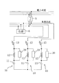
図2は、本発明の実施形態に係る電力系統に対する進相コンデンサ装置の配置関係を示す電気回路図である。同図に示すように、負荷(3相負荷)6を有する負荷系統に対して、電力系統から遮断器5を介して負荷系統に電力が供給される。そして、負荷系統において、各負荷6とは並列に、3相分の進相コンデンサ装置10が配置されている。
FIG. 2 is an electric circuit diagram showing an arrangement relationship of the phase advance capacitor device with respect to the power system according to the embodiment of the present invention. As shown in the figure, power is supplied from a power system to a load system via a
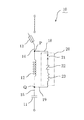
図1は、本発明の実施形態に係る各相ごとの進相コンデンサ装置10の構成を示す電気回路図である。同図に示すように、本実施形態の進相コンデンサ装置10は、電力系統に挿入された進相コンデンサ11と、配線15により進相コンデンサ11に電気的に接続された直列リアクトル12と、配線14により直列リアクトル12に電気的に接続されたヒューズ付きスイッチ13とを備えている。また、配線14の接続点Pと、配線15の接続点Qとにそれぞれリード線18,19の各一端が接続されており、各リード線18,19の各他端は高調波引き込み現象防止装置20の両端に接続されている。すなわち、高調波引き込み現象防止装置20は、進相コンデンサ11に対して、直列リアクトル12とは並列に電気的に接続されている。
FIG. 1 is an electric circuit diagram showing a configuration of a phase
ここで、高調波引き込み現象防止装置20は、定電圧スイッチング部であるギャップ素子21およびバリスタ素子22からなる直列接続体と、抵抗部としての抵抗素子23とを直列に接続して構成されている。この定電圧スイッチング部は、本実施形態のようなギャップ素子とバリスタ素子との組み合わせのほかに、ギャップ素子単独,バリスタ素子単独,双方向サイリスタ素子単独,双方向サイリスタ素子とギャップ素子との組み合わせ,もしくは双方向サイリスタ素子とバリスタ素子との組み合わせなどによっても構成することができる。つまり、定電圧スイッチング部は、バリスタ素子,ギャップ素子、双方向性サイリスタ素子およびこれらの組み合わせのうちのいずれかによって構成することができる。電圧ひずみの比較的小さい線路で使用される高調波引き込み現象防止装置には、ギャップ素子を必ずしも設ける必要はなく、その場合にも後述する効果を奏することが可能である。
Here, the harmonic
本実施形態の高調波引き込み現象防止装置20を設けたことにより、後述するように、電源投入時の進相コンデンサ11や直列リアクトル12への突入電流を抑制し、かつ、その後の過渡振動もすばやく消滅させ得ることが、フィールド試験において確認された。
By providing the harmonic entrainment
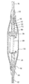
図3は、実施形態に係る高調波引き込み現象防止装置20の組立状態の構造を示す部分断面図である。同図に示すように、本実施形態の高調波引き込み現象防止装置20は、プラスチック製の紡錘型の容器50内に、抵抗素子60と、バリスタ素子70と、ギャップ素子80とを収納し、両端の端子55,56からそれぞれリード線に相当する高圧配線91,92を導出して構成されている。容器50内において、接続金具51と端子55との間はリード線52によって電気的に接続されているとともに、接続金具51と端子55との間に介在する圧縮コイルバネ53によって各パーツ間の強固な接続が確保されている。また、高圧配線91,92と容器50とは防水用のゴム製キャップ93,94により、互いに固定されている。さらに、容器50の大部分を覆うとともに、キャップ93,94の容器50側の端部を覆う圧縮性チューブ96が設けられている。バリスタ素子70には、たとえばZnOを主成分とし、それ自体が非直線抵抗特性を有するセラミック体に電極を付設したZnOバリスタ素子を用いることが好ましい。
FIG. 3 is a partial cross-sectional view showing the structure of the assembled state of the harmonic
このような構造により、製造コストが安価で、コンパクトな高調波引き込み現象防止装置20が得られる。
With such a structure, it is possible to obtain a compact harmonic entrainment
図4は、本実施形態に係る高調波引き込み現象防止装置の進相コンデンサ装置への取り付け状態を示す斜視図である。同図に示すように、本実施形態の高調波引き込み現象防止装置20は、各相ごとに一つのユニットに一体化されており、既存の進相コンデンサ装置に取り付け可能に構成されている。ここにいう既存の進相コンデンサ装置は、主要部材として、3相分のヒューズ付きスイッチ13と、3相分の進相コンデンサ11を収納している進相コンデンサユニット11Aと、3相分の直列リアクトル12を収納している直列リアクトルユニット12Aとを備え、各直列リアクトル12と各ヒューズ付きスイッチ13とは対応するもの同士がそれぞれ配線14により接続され、また、各進相コンデンサ11と各直列リアクトル12とは配線l5により同様に接続されている。
FIG. 4 is a perspective view showing a state in which the harmonic entrainment phenomenon preventing device according to the present embodiment is attached to the phase advance capacitor device. As shown in the figure, the harmonic
そして、本実施形態の進相コンデンサ装置10は、既存の進相コンデンサ装置に、3相分の高調波引き込み現象防止装置20を取り付けたものである。すなわち、各高調波引き込み現象防止装置20の一つの端子から延びる配線18は、各直列リアクトル12の一つの端子から延びる配線14および各ヒューズ付きスイッチ13に接続点Pにおいて接続されており、各高調波引き込み現象防止装置20の他の端子から延びる配線19は、各直列リアクトル12の他の端子から延びる配線15および各進相コンデンサ11の端子に接続点Qにおいて接続されている。
And the phase advance capacitor |
このような高調波引き込み現象防止装置20の構造により、後述するように、高調波引き込み現象を確実に防止することができるとともに、電源系統への投入時の突入電流を効果的に抑制でき、電源系統の電圧動揺を低減することが可能であり、また装置全体の小型化が可能であり、かつ製造コストも安価であり、しかも、進相コンデンサ装置への取り付けも容易である。
As will be described later, the structure of the harmonic entrainment
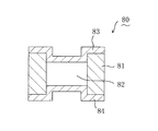
図5は、本実施形態の高調波引き込み現象防止装置20中に配置されているギャップ素子80の構造を示す断面図である。ギャップ素子80は、セラミック製の筒状体81の両端に金属製の電極83,84を取り付け、内部に不活性ガス82を封入して構成されている。このギャップ素子80の両端の電極83,84間に、放電開始電圧を超える電圧が印加されると、不活性ガス82が絶縁破壊して放電が生じ、電極83,84間に電流が流れる。
FIG. 5 is a cross-sectional view showing the structure of the
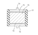
図6は、本実施形態の高調波引き込み現象防止装置20中に配置されているバリスタ素子70の構造を示す断面図である。同図に示すように、バリスタ素子70は、電圧非直線性抵抗特性を発現させる成分,たとえばBi,Co,MnおよびSbなど、もしくはPrなどを含有する円柱状のZnOセラミック体75と、アルミニウム溶射などによってZnOセラミック体75の両端に設けられた円板状の電極71,72と、ZnOセラミック体75,各電極71,72および端子電極73,74からなる円柱体の側面を被覆するシリコーン樹脂などの絶縁被覆体77とを備えている。電極71,72は、ZnOセラミック体75を挟んで相対向しており、端子電極73,74間にしきい値電圧を超える電圧が印加されると、電極71,72間を埋めるZnOセラミック体75が導通状態となり、電極71,72間に電流が流れる。
FIG. 6 is a cross-sectional view showing the structure of the
なお、本実施形態で用いられる抵抗素子60としては、抵抗値が50Ω〜2kΩの範囲内にある一般的な抵抗素子を用いることができる。
As the
次に、発明者が行なった高調波引き込み現象防止装置20の構造と作用,効果の関係に関する試験結果について説明する。
Next, the test results regarding the relationship between the structure, action, and effect of the harmonic
ここで、鉄共振が発生するためには、進相コンデンサに直列に接続された直列リアクトルが磁気飽和を起こすことが条件となる。一般に、リアクトルの電流は、V・dtに応じて増大するので、周波数の高い(つまりdtが小さい)高調波によって磁気飽和を生じるには、リアクトル両端に比較的高い電圧が印加される必要がある。そこで、発明者が行なった試験においては、リアクトルの両端に高電圧が印加されたときに、リアクトルや進相コンデンサに大電流が流れない回路構成について検討した。 Here, in order for iron resonance to occur, it is a condition that the series reactor connected in series with the phase advance capacitor causes magnetic saturation. In general, the current of the reactor increases in accordance with V · dt. Therefore, in order to cause magnetic saturation due to a harmonic having a high frequency (that is, having a small dt), it is necessary to apply a relatively high voltage across the reactor. . Therefore, in a test conducted by the inventors, a circuit configuration in which a large current does not flow through the reactor and the phase advance capacitor when a high voltage is applied to both ends of the reactor was examined.
図7は、比較例としての、高調波引き込み現象防止装置を有していない進相コンデンサ装置を、電力系統に接続した後の電圧と電流のシミュレーション波形を示す図である。図7において、Vdは3800Vの電源電圧、Icはコンデンサ電流を示している。この進相コンデンサの定格電流が4.37Aであるのに対して、時間が経過してもコンデンサ電流Icの電流実効値が18Aを越え、これから、鉄共振状態が持続して高調波引き込み現象が生じていることがわかる。そして、このような大電流が直列リアクトルを流れることにより、それがいちじるしく発熱して加熱状態となり、焼損のる。これによって進相コンデンサ装置に設けてある保護装置が動作して、あるいは保護装置を設けていない場合には直列リアクトルが焼損に至る可能性がある。 FIG. 7 is a diagram showing voltage and current simulation waveforms after a phase advance capacitor device that does not have a harmonic entrainment prevention device as a comparative example is connected to the power system. In FIG. 7, Vd represents a power supply voltage of 3800 V, and Ic represents a capacitor current. While the rated current of the phase advance capacitor is 4.37 A, the effective current value of the capacitor current Ic exceeds 18 A even after a lapse of time. You can see that it has occurred. Then, when such a large current flows through the series reactor, it is extremely heated to be in a heated state and burned out. As a result, the protective device provided in the phase-advancing capacitor device operates, or if the protective device is not provided, the series reactor may burn out.
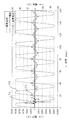
図8は、本実施形態の高調波引き込み現象防止装置を取り付けた場合の進相コンデンサ装置の相電流波形および防止装置に加わる電流波形のシミュレーション結果を示す図である。図8において、Vdは電源電圧、Icはコンデンサ電流、Izは高調波引き込み現象防止装置に流れる防止装置電流を示している。 FIG. 8 is a diagram showing simulation results of the phase current waveform of the phase advance capacitor device and the current waveform applied to the prevention device when the harmonic entrainment phenomenon prevention device of the present embodiment is attached. In FIG. 8, Vd indicates a power supply voltage, Ic indicates a capacitor current, and Iz indicates a prevention device current that flows through the harmonic entrainment phenomenon prevention device.
図8に示すように、本実施形態によれば、進相コンデンサ装置の電力系統接続時に生じる電流の突入現象は直列リアクトルによって効果的に抑制され、コンデンサ電流Icが大幅に低減されることがわかる。そして、この電流で鉄共振が発生するものの、高調波引き込み現象防止装置に防止装置電流Izが流れることで、コンデンサ電流Icの過渡振動が1〜2周期前後のきわめて短期間に収まってその電流実効値が4.8Aまで減少しており、高調波引き込み現象が非常に短い期間で終息している。そして、高調波引き込み現象防止装置に流れる防止装置電流Izも、進相コンデンサ装置を系統に接続した直後に波高値で4.9A流れるが、すみやかにほぼ0にまで減衰している。 As shown in FIG. 8, according to the present embodiment, it is understood that the inrush phenomenon of current that occurs when the phase advance capacitor device is connected to the power system is effectively suppressed by the series reactor, and the capacitor current Ic is greatly reduced. . And although iron resonance occurs with this current, when the prevention device current Iz flows through the harmonic entrainment phenomenon prevention device, the transient oscillation of the capacitor current Ic is settled in a very short period of about 1 to 2 cycles, and the current effective The value has decreased to 4.8 A, and the harmonic entrainment phenomenon has ended in a very short period. The prevention device current Iz flowing through the harmonic entrainment prevention device also flows at a peak value of 4.9 A immediately after the phase advance capacitor device is connected to the system, but quickly decays to almost zero.
すなわち、図7,図8の結果を比較することにより、上述のような本発明の効果が検証されたことになる。また、発明者による実験によると、以下のことが確認されている。 That is, by comparing the results of FIGS. 7 and 8, the effects of the present invention as described above have been verified. Moreover, according to the experiment by the inventor, the following has been confirmed.
リアクトルが磁気飽和して鉄共振に至るような電圧(接続される系統電圧の1/3から1/8)が直列リアクトルに加わったとき、定電圧スイッチング部(本実施形態ではバリスタ素子)が導通し、進相コンデンサから直列リアクトルに流れる電流の一部分が抵抗部(本実施形態では抵抗素子)にバイパスされて、電源系統に過電流が徐々に放出されるので、鉄共振をきわめて短期間に消息させることができる。 When a voltage that causes magnetic resonance of the reactor and causes iron resonance (1/3 to 1/8 of the connected system voltage) is applied to the series reactor, the constant voltage switching unit (varistor element in this embodiment) becomes conductive. However, a part of the current flowing from the phase advance capacitor to the series reactor is bypassed to the resistor section (resistive element in this embodiment), and overcurrent is gradually released to the power supply system, so that the iron resonance can be absorbed in a very short time. Can be made.
鉄共振が収まった状態においては、直列リアクトルの両端に加わる電圧が所定の値まで低下するため、定電圧スイッチング部は自動的に開放状態になる。 In the state where the iron resonance is settled, the voltage applied to both ends of the series reactor is lowered to a predetermined value, so that the constant voltage switching unit is automatically opened.
また、高調波引き込み現象防止装置において、抵抗部の抵抗が低くすぎると、抵抗部および定電圧スイッチング部に分流する突入電流の比率が大きくなり、直列リアクトルの突入電流抑制作用による効果がいちじるしく減殺される。これにより、進相コンデンサ投入時に電源系統に大きな電圧動揺を生じさせる。抵抗部の抵抗が高すぎると、直列リアクトルの電流抑制作用が得られるものの、電源系統への投入で発生した進相コンデンサ・直列リアクトル間の鉄共振時の過電流を電源側へ放出するのに要する期間が長くなり、鉄共振を早期に終息させることが困難となる。実験によれば、6.6kVコンデンサ用の6%リアクトルで、抵抗部の抵抗値が50Ω以上で、2kΩの範囲内にあるときに、高調波引き込み現象防止装置が直列リアクトルの突入電流抑制作用に実使用に支障を生じるような影響を与えることがなく、なおかつ鉄共振現象がきわめて短期間に終息することが確認された。さらには、抵抗部を300Ω〜2kΩの高抵抗とすることによって、より望ましい効果が得られることが検証された。 In addition, in the harmonic entrainment prevention device, if the resistance of the resistance section is too low, the ratio of the inrush current that is shunted to the resistance section and the constant voltage switching section is increased, and the effect of the inrush current suppressing action of the series reactor is greatly reduced. The This causes a large voltage fluctuation in the power supply system when the phase advance capacitor is turned on. If the resistance of the resistance section is too high, the current suppression action of the series reactor can be obtained, but the overcurrent at the time of iron resonance between the phase advance capacitor and the series reactor generated by turning on the power supply system is released to the power supply side. The required time becomes longer and it becomes difficult to terminate the iron resonance early. According to experiments, when a 6% reactor for a 6.6 kV capacitor has a resistance value of 50Ω or more and within a range of 2 kΩ, the harmonic entrainment prevention device is effective in suppressing the inrush current of the series reactor. It was confirmed that the iron resonance phenomenon was terminated in a very short time without affecting the actual use. Furthermore, it was verified that a more desirable effect can be obtained by setting the resistance portion to a high resistance of 300Ω to 2 kΩ.
また、バリスタ素子に印加される電圧を検証した結果、電圧歪が上昇した場合の常時印加電圧がバリスタ素子の放電開始電圧に近い場合には、漏れ電流による熱暴走のおそれがある。それに対して、ギャップ素子をバリスタ素子に直列に接続することにより、この現象を抑制しうることがわかった。大型のバリスタ素子を用いると、ギャップ素子を別途設けなくても漏れ電流は抑制することが可能であるが、高調波引き込み現象防止装置全体をコンパクトにするためには、ギャップ素子を設けた構造が好ましい。 Further, as a result of verifying the voltage applied to the varistor element, if the always applied voltage when the voltage distortion increases is close to the discharge start voltage of the varistor element, there is a risk of thermal runaway due to leakage current. On the other hand, it was found that this phenomenon can be suppressed by connecting the gap element in series with the varistor element. If a large varistor element is used, the leakage current can be suppressed without providing a gap element separately. However, in order to make the whole harmonic entrainment prevention device compact, a structure with a gap element is required. preferable.
なお、前記実施形態においては、バリスタ素子70,抵抗素子60およびギャップ素子80を一つの容器50内に収納して高調波引き込み現象防止装置20を一体化しているが、各部材を必ずしも共通の容器に収納する必要はない。進相コンデンサ装置10において、たとえばバリスタ素子およびギャップ素子とを一つの容器に収納し、抵抗部としての抵抗素子を外付けしたり、各部材を個別に配置し接続したりすることにより、高調波引き込み現象防止装置20を構成しても、直列リアクトルのもつ突入電流抑制作用を損なうことなく、高調波引き込み現象をきわめて短期間に終息させるという基本的な効果を発揮させることができる。なお、図3に示す構造において、高調波引き込み現象防止装置20の両端から高圧配線91,92を引き出しておく必要もなく、高周波引き込み現象防止装置20の両端からなんらかの電気的接続用の導体部材が露出していれば、図4に示すような構成を容易に実現することができる。
In the above-described embodiment, the
また、図4に示す3本の高周波引き込み現象防止装置20を共通の保持部材によって一つのユニットにすることも可能である。その場合、図4に示す3個の高周波引き込み現象防止装置20と、直列リアクトルユニット12Aとを共通の保持部材によって一つのユニットに一体化することも可能である。さらに、図4に示す1個の高周波引き込み現象防止装置20と1個の直列リアクトル12とを、共通の保持部材によって一つのユニットに一体化することも可能である。
Also, the three high-frequency pull-in
本発明の進相コンデンサ装置および高調波引き込み現象防止装置は、電力系統から負荷系統に電力を供給するシステムに利用することができる。 The phase advance capacitor device and the harmonic entrainment phenomenon prevention device of the present invention can be used in a system for supplying power from a power system to a load system.
5 遮断器
6 負荷
10 進相コンデンサ装置
11 進相コンデンサ
12 直列リアクトル
13 ヒューズ付きスイッチ
14,15 配線
18,19 リード線
20 高調波引き込み現象防止装置
21 ギャップ素子
22 バリスタ素子
23 抵抗素子
50 容器
51 接続金具
52 リード線
53 圧縮コイルバネ
55,56 端子
60 抵抗素子
70 バリスタ素子
71,72 電極
73,74 端子電極
75 ZnOセラミック体
77 被覆絶縁層
80 ギャップ素子
81 筒状体
82 不活性ガス
83,84 電極
91,92 高圧配線
93,94 防水用のキャップ
96 圧縮性チューブ
DESCRIPTION OF
Claims (12)
定電圧スイッチング部と、前記定電圧スイッチング部に直列に接続された抵抗部とを有し、
前記定電圧スイッチング部の導通開始電圧が、前記リアクトルに正常時に印加される電圧より高く、
前記抵抗部の抵抗値が50Ω〜2kΩの範囲内であることを特徴とする高調波引き込み現象防止装置。 A phase-advancing capacitor device having a phase-advancing capacitor and a reactor connected in series to the phase-advancing capacitor, and a harmonic entrainment phenomenon preventing device connected in series with the phase-advancing capacitor and in parallel with the reactor Because
A constant voltage switching unit, and a resistance unit connected in series to the constant voltage switching unit,
The conduction start voltage of the constant voltage switching unit is higher than the voltage applied to the reactor at a normal time,
A resistance device for harmonic entrainment phenomenon, wherein the resistance value of the resistance portion is in a range of 50Ω to 2 kΩ.
前記定電圧スイッチング部は、バリスタ素子、ギャップ素子、双方向性サイリスタ素子およびこれらの組み合わせのうちのいずれかによって構成されている高調波引き込み現象防止装置。 In the harmonic entrainment phenomenon prevention device according to claim 1,
The constant voltage switching unit is a harmonic entrainment phenomenon prevention device configured by any one of a varistor element, a gap element, a bidirectional thyristor element, and a combination thereof.
前記定電圧スイッチング部がZnOバリスタ素子である高調波引き込み現象防止装置。 In the harmonic entrainment phenomenon prevention device according to claim 1,
Harmonic entrainment phenomenon prevention device, wherein the constant voltage switching unit is a ZnO varistor element.
少なくとも前記定電圧スイッチング部および前記抵抗部に電気的に接続された外部接続用の1対の端子と、
少なくとも前記定電圧スイッチング部、前記抵抗部および前記端子を一体的に収納した容器とをさらに備えて設けられている高調波引き込み現象防止装置。 In the harmonic entrainment phenomenon prevention device according to claim 1,
A pair of terminals for external connection electrically connected to at least the constant voltage switching unit and the resistor unit;
The harmonic entrainment phenomenon prevention apparatus further provided with the container which accommodated at least the said constant voltage switching part, the said resistance part, and the said terminal integrally.
前記1対の端子にそれぞれ電気的に接続された1対の導電部材をさらに備えている高調波引き込み現象防止装置。 In the harmonic entrainment phenomenon prevention device according to claim 4,
The harmonic entrainment phenomenon preventing apparatus further comprising a pair of conductive members electrically connected to the pair of terminals, respectively.
前記1対の導電部材は、既存の進相コンデンサおよびリアクトルに取り付け可能である高調波引き込み現象防止装置。 In the harmonic entrainment phenomenon prevention device according to claim 5,
The harmonic entrainment phenomenon prevention device, wherein the pair of conductive members can be attached to an existing phase advance capacitor and a reactor.
前記進相コンデンサに直列に接続されるリアクトルと、
前記進相コンデンサに対して、前記リアクトルとは並列に、かつ互いに直列に接続された定電圧スイッチング部と抵抗部とを備え、
前記定電圧スイッチング部の導通開始電圧が、前記リアクトルに正常時に印加される電圧より高く、
前記抵抗部の抵抗値が50Ω〜2kΩの範囲内であることを特徴とするリアクトル装置。 A reactor device connected in series with a phase advance capacitor in a phase advance capacitor device of a power system,
A reactor connected in series to the phase advance capacitor;
For the phase advance capacitor, the reactor includes a constant voltage switching unit and a resistor unit connected in parallel with each other and in series with each other,
The conduction start voltage of the constant voltage switching unit is higher than the voltage applied to the reactor at a normal time,
The reactor device has a resistance value in a range of 50Ω to 2 kΩ.
前記定電圧スイッチング部が、バリスタ素子、ギャップ素子、双方向性サイリスタ素子およびこれらの組み合わせのうちのいずれかによって構成されているリアクトル装置。 The reactor device according to claim 7,
A reactor device in which the constant voltage switching unit includes any one of a varistor element, a gap element, a bidirectional thyristor element, and a combination thereof.
前記定電圧スイッチング部がZnOバリスタ素子であるリアクトル装置。 The reactor device according to claim 7,
A reactor device in which the constant voltage switching unit is a ZnO varistor element.
前記進相コンデンサに直列に接続されるリアクトルと、
前記進相コンデンサに対して、前記リアクトルと並列に、かつ互いに直列に接続された定電圧スイッチング部と抵抗部とを備え、
前記定電圧スイッチング部の導通開始電圧が、前記リアクトルに正常時に印加される電圧より高く、
前記抵抗部の抵抗値が50Ω〜2kΩの範囲内であることを特徴とする進相コンデンサ装置。 A phase advance capacitor inserted in the power system;
A reactor connected in series to the phase advance capacitor;
For the phase advance capacitor, a constant voltage switching unit and a resistance unit connected in parallel with each other and in series with the reactor,
The conduction start voltage of the constant voltage switching unit is higher than the voltage applied to the reactor at a normal time,
A phase advance capacitor device, wherein the resistance value of the resistance portion is in a range of 50Ω to 2 kΩ.
前記定電圧スイッチング部が、バリスタ素子、ギャップ素子、双方向性サイリスタ素子およびこれらの組み合わせのうちのいずれかによって構成されている進相コンデンサ装置。 The phase advance capacitor device according to claim 10,
A phase advance capacitor device in which the constant voltage switching unit is configured by any one of a varistor element, a gap element, a bidirectional thyristor element, and a combination thereof.
前記定電圧スイッチング部がZnOバリスタ素子である進相コンデンサ装置。 The phase advance capacitor device according to claim 10,
A phase advance capacitor device in which the constant voltage switching unit is a ZnO varistor element.
Priority Applications (1)
| Application Number | Priority Date | Filing Date | Title |
|---|---|---|---|
| JP2004251649A JP4085085B2 (en) | 2004-03-09 | 2004-08-31 | Harmonic entrainment prevention device, reactor device, and phase advance capacitor device |
Applications Claiming Priority (2)
| Application Number | Priority Date | Filing Date | Title |
|---|---|---|---|
| JP2004065242 | 2004-03-09 | ||
| JP2004251649A JP4085085B2 (en) | 2004-03-09 | 2004-08-31 | Harmonic entrainment prevention device, reactor device, and phase advance capacitor device |
Publications (2)
| Publication Number | Publication Date |
|---|---|
| JP2005295783A true JP2005295783A (en) | 2005-10-20 |
| JP4085085B2 JP4085085B2 (en) | 2008-04-30 |
Family
ID=35328091
Family Applications (1)
| Application Number | Title | Priority Date | Filing Date |
|---|---|---|---|
| JP2004251649A Expired - Lifetime JP4085085B2 (en) | 2004-03-09 | 2004-08-31 | Harmonic entrainment prevention device, reactor device, and phase advance capacitor device |
Country Status (1)
| Country | Link |
|---|---|
| JP (1) | JP4085085B2 (en) |
Cited By (1)
| Publication number | Priority date | Publication date | Assignee | Title |
|---|---|---|---|---|
| JP2021029070A (en) * | 2019-08-09 | 2021-02-25 | 国立大学法人東京工業大学 | Active filter device for power system |
-
2004
- 2004-08-31 JP JP2004251649A patent/JP4085085B2/en not_active Expired - Lifetime
Cited By (2)
| Publication number | Priority date | Publication date | Assignee | Title |
|---|---|---|---|---|
| JP2021029070A (en) * | 2019-08-09 | 2021-02-25 | 国立大学法人東京工業大学 | Active filter device for power system |
| JP7274209B2 (en) | 2019-08-09 | 2023-05-16 | 国立大学法人東京工業大学 | Active filter device for power system |
Also Published As
| Publication number | Publication date |
|---|---|
| JP4085085B2 (en) | 2008-04-30 |
Similar Documents
| Publication | Publication Date | Title |
|---|---|---|
| US10498138B2 (en) | Protective circuit for a current transformer and current transformer with a protection circuit | |
| CN105103393B (en) | Arrangement for overload protection of overvoltage protectors | |
| CN111837308B (en) | Novel lightning protection overvoltage crowbar and protection device | |
| US8400744B2 (en) | Earth leakage detection module with robust transient suppression | |
| CA2060641C (en) | Surge absorber | |
| CN104393562B (en) | Overvoltage and electric leakage comprehensive protective circuit breaker | |
| CN111869031B (en) | Lightning protection overvoltage protection circuit and protection device | |
| JPH08103023A (en) | Voltage clamping circuit | |
| JP2014501435A (en) | A device that combines a thermal fuse and a resistor | |
| US6327129B1 (en) | Multi-stage surge protector with switch-grade fail-short mechanism | |
| CA2063654C (en) | Surge absorber for protection of communication equipment connected to communication lines | |
| US5200875A (en) | Protection structure for a surge absorber | |
| JP4085085B2 (en) | Harmonic entrainment prevention device, reactor device, and phase advance capacitor device | |
| US6069781A (en) | Device for protecting medium voltage equipment against voltage surges | |
| US4677348A (en) | Combined ignitor and transient suppressor for gaseous discharge lighting equipment | |
| CN109066640B (en) | Novel lightning protection overvoltage protection device | |
| CN105981251B (en) | An overvoltage protection device with leakage current cutoff | |
| JPH10144540A (en) | Secondary open circuit protection device for current transformer | |
| JP2991266B2 (en) | Gas circuit breaker | |
| KR101390387B1 (en) | System preventing thermal runway for varistor | |
| CA1208282A (en) | Current transformer secondary voltage limiter | |
| Traynham et al. | Using Thermally Protected MOVs in TVSS or Power Supply Applications | |
| RU35039U1 (en) | High voltage disconnector | |
| RU2002130234A (en) | DEVICE FOR CONTROL OF RESISTANCE OF INSULATION AND PROTECTION OF ELECTRIC MACHINES AND APPLIANCES (OPTIONS) | |
| KR200212603Y1 (en) | Lightning arrester device |
Legal Events
| Date | Code | Title | Description |
|---|---|---|---|
| A621 | Written request for application examination |
Free format text: JAPANESE INTERMEDIATE CODE: A621 Effective date: 20051125 |
|
| A977 | Report on retrieval |
Free format text: JAPANESE INTERMEDIATE CODE: A971007 Effective date: 20070618 |
|
| A131 | Notification of reasons for refusal |
Free format text: JAPANESE INTERMEDIATE CODE: A131 Effective date: 20070626 |
|
| A521 | Request for written amendment filed |
Free format text: JAPANESE INTERMEDIATE CODE: A523 Effective date: 20070824 |
|
| A02 | Decision of refusal |
Free format text: JAPANESE INTERMEDIATE CODE: A02 Effective date: 20071023 |
|
| A521 | Request for written amendment filed |
Free format text: JAPANESE INTERMEDIATE CODE: A523 Effective date: 20071221 |
|
| A911 | Transfer to examiner for re-examination before appeal (zenchi) |
Free format text: JAPANESE INTERMEDIATE CODE: A911 Effective date: 20080108 |
|
| TRDD | Decision of grant or rejection written | ||
| A01 | Written decision to grant a patent or to grant a registration (utility model) |
Free format text: JAPANESE INTERMEDIATE CODE: A01 Effective date: 20080205 |
|
| A61 | First payment of annual fees (during grant procedure) |
Free format text: JAPANESE INTERMEDIATE CODE: A61 Effective date: 20080218 |
|
| R150 | Certificate of patent or registration of utility model |
Ref document number: 4085085 Country of ref document: JP Free format text: JAPANESE INTERMEDIATE CODE: R150 Free format text: JAPANESE INTERMEDIATE CODE: R150 |
|
| FPAY | Renewal fee payment (event date is renewal date of database) |
Free format text: PAYMENT UNTIL: 20110222 Year of fee payment: 3 |
|
| FPAY | Renewal fee payment (event date is renewal date of database) |
Free format text: PAYMENT UNTIL: 20120222 Year of fee payment: 4 |
|
| R250 | Receipt of annual fees |
Free format text: JAPANESE INTERMEDIATE CODE: R250 |
|
| FPAY | Renewal fee payment (event date is renewal date of database) |
Free format text: PAYMENT UNTIL: 20130222 Year of fee payment: 5 |
|
| R250 | Receipt of annual fees |
Free format text: JAPANESE INTERMEDIATE CODE: R250 |
|
| FPAY | Renewal fee payment (event date is renewal date of database) |
Free format text: PAYMENT UNTIL: 20130222 Year of fee payment: 5 |
|
| FPAY | Renewal fee payment (event date is renewal date of database) |
Free format text: PAYMENT UNTIL: 20160222 Year of fee payment: 8 |
|
| R250 | Receipt of annual fees |
Free format text: JAPANESE INTERMEDIATE CODE: R250 |
|
| R250 | Receipt of annual fees |
Free format text: JAPANESE INTERMEDIATE CODE: R250 |
|
| R250 | Receipt of annual fees |
Free format text: JAPANESE INTERMEDIATE CODE: R250 |
|
| R250 | Receipt of annual fees |
Free format text: JAPANESE INTERMEDIATE CODE: R250 |
|
| R250 | Receipt of annual fees |
Free format text: JAPANESE INTERMEDIATE CODE: R250 |
|
| R250 | Receipt of annual fees |
Free format text: JAPANESE INTERMEDIATE CODE: R250 |
|
| R250 | Receipt of annual fees |
Free format text: JAPANESE INTERMEDIATE CODE: R250 |
|
| R250 | Receipt of annual fees |
Free format text: JAPANESE INTERMEDIATE CODE: R250 |
|
| R250 | Receipt of annual fees |
Free format text: JAPANESE INTERMEDIATE CODE: R250 |
|
| EXPY | Cancellation because of completion of term |