JP2005295775A - Motor rotor - Google Patents
Motor rotor Download PDFInfo
- Publication number
- JP2005295775A JP2005295775A JP2004111533A JP2004111533A JP2005295775A JP 2005295775 A JP2005295775 A JP 2005295775A JP 2004111533 A JP2004111533 A JP 2004111533A JP 2004111533 A JP2004111533 A JP 2004111533A JP 2005295775 A JP2005295775 A JP 2005295775A
- Authority
- JP
- Japan
- Prior art keywords
- rotor
- motor
- pole
- plastic magnet
- magnet
- Prior art date
- Legal status (The legal status is an assumption and is not a legal conclusion. Google has not performed a legal analysis and makes no representation as to the accuracy of the status listed.)
- Pending
Links
Images

Classifications
-
- H—ELECTRICITY
- H02—GENERATION; CONVERSION OR DISTRIBUTION OF ELECTRIC POWER
- H02K—DYNAMO-ELECTRIC MACHINES
- H02K1/00—Details of the magnetic circuit
- H02K1/06—Details of the magnetic circuit characterised by the shape, form or construction
- H02K1/22—Rotating parts of the magnetic circuit
- H02K1/27—Rotor cores with permanent magnets
- H02K1/2706—Inner rotors
- H02K1/272—Inner rotors the magnetisation axis of the magnets being perpendicular to the rotor axis
- H02K1/274—Inner rotors the magnetisation axis of the magnets being perpendicular to the rotor axis the rotor consisting of two or more circumferentially positioned magnets
- H02K1/2753—Inner rotors the magnetisation axis of the magnets being perpendicular to the rotor axis the rotor consisting of two or more circumferentially positioned magnets the rotor consisting of magnets or groups of magnets arranged with alternating polarity
-
- H—ELECTRICITY
- H02—GENERATION; CONVERSION OR DISTRIBUTION OF ELECTRIC POWER
- H02K—DYNAMO-ELECTRIC MACHINES
- H02K1/00—Details of the magnetic circuit
- H02K1/06—Details of the magnetic circuit characterised by the shape, form or construction
- H02K1/22—Rotating parts of the magnetic circuit
- H02K1/28—Means for mounting or fastening rotating magnetic parts on to, or to, the rotor structures
-
- H—ELECTRICITY
- H02—GENERATION; CONVERSION OR DISTRIBUTION OF ELECTRIC POWER
- H02K—DYNAMO-ELECTRIC MACHINES
- H02K15/00—Processes or apparatus specially adapted for manufacturing, assembling, maintaining or repairing of dynamo-electric machines
- H02K15/02—Processes or apparatus specially adapted for manufacturing, assembling, maintaining or repairing of dynamo-electric machines of stator or rotor bodies
- H02K15/03—Processes or apparatus specially adapted for manufacturing, assembling, maintaining or repairing of dynamo-electric machines of stator or rotor bodies having permanent magnets
-
- H—ELECTRICITY
- H02—GENERATION; CONVERSION OR DISTRIBUTION OF ELECTRIC POWER
- H02K—DYNAMO-ELECTRIC MACHINES
- H02K21/00—Synchronous motors having permanent magnets; Synchronous generators having permanent magnets
- H02K21/12—Synchronous motors having permanent magnets; Synchronous generators having permanent magnets with stationary armatures and rotating magnets
- H02K21/14—Synchronous motors having permanent magnets; Synchronous generators having permanent magnets with stationary armatures and rotating magnets with magnets rotating within the armatures
- H02K21/16—Synchronous motors having permanent magnets; Synchronous generators having permanent magnets with stationary armatures and rotating magnets with magnets rotating within the armatures having annular armature cores with salient poles
Landscapes
- Engineering & Computer Science (AREA)
- Power Engineering (AREA)
- Manufacturing & Machinery (AREA)
- Permanent Field Magnets Of Synchronous Machinery (AREA)
Abstract
Description
本発明は、ブラシレスDCモータ、単相同期モータなどのモータの回転子に関するものである。 The present invention relates to a rotor of a motor such as a brushless DC motor or a single phase synchronous motor.
ブラシレスDCモータなどのモータにおける回転子は、磁力を得るためにS極とN極とを交互になるようにマグネットが配されている(例えば、特許文献1参照)。 A rotor in a motor such as a brushless DC motor is provided with magnets so that S poles and N poles are alternated in order to obtain magnetic force (see, for example, Patent Document 1).
このような回転子においては、回転子鉄心の表面にマグネットを配するSPM型(SURFACE PERMANENT MAGNET型)の回転子がある。
上記のようなSPM型の回転子において用いられているマグネットは、フェライト系プラスチックマグネットが多く、内外径が同心のリング状であって、回転子鉄心に一体成形または嵌合して構成されている。そして、所定角度毎に、極異方性の磁場配向をかけている。 The magnets used in the SPM type rotor as described above are mostly ferrite plastic magnets, are concentric rings with inner and outer diameters, and are integrally formed or fitted to the rotor core. . Then, polar anisotropic magnetic field orientation is applied at every predetermined angle.
このようなリング状のマグネットにおいて、S極とN極の境部分については、配向の力が弱いにもかかわらず、各マグネットの中心、すなわち極の中心と同じ量のマグネットを使用している。 In such a ring-shaped magnet, at the boundary between the S pole and the N pole, the same amount of magnet is used as the center of each magnet, that is, the center of the pole, although the orientation force is weak.
このように極中心と同じ量のマグネットを用いると、プラスチックマグネットの量が多くなり、コストが上昇するという問題点がある。 If the same amount of magnet as the pole center is used in this way, there is a problem that the amount of plastic magnet increases and the cost increases.
また、リング状のマグネットであるため、回転子鉄心に対し嵌合が弱い場合には、回転子鉄心のみが回転したり、リング状のマグネットのみが回転したりするという問題点がある。 Moreover, since it is a ring-shaped magnet, when the fitting with the rotor core is weak, there is a problem that only the rotor core rotates or only the ring-shaped magnet rotates.
そこで、本発明は上記問題点に鑑み、プラスチックマグネットの量を減らすことができると共に、マグネットが回転子鉄心に対し回動しないモータの回転子を提供する。 In view of the above problems, the present invention provides a rotor for a motor that can reduce the amount of plastic magnets and that does not rotate the magnet with respect to the rotor core.
請求項1に係る発明は、回転子の外周側がS極に着磁され内周側がN極に着磁されたプラスチックマグネットと、前記回転子の外周側がN極に着磁され内周側がS極に着磁されたプラスチックマグネットとが交互に一極毎に回転子鉄心の外周面に設けられたモータの回転子において、前記各極のプラスチックマグネットにおける内周側の断面形状が、中央部を膨らませ端部にいくほど細くなる曲面形状であり、前記各極のプラスチックマグネットがリング状に連結され、前記回転子鉄心の外周部に前記各極のプラスチックマグネットに対応する凹部が形成されていることを特徴とするモータの回転子である。 The invention according to claim 1 is a plastic magnet in which the outer peripheral side of the rotor is magnetized to the S pole and the inner peripheral side is magnetized to the N pole, and the outer peripheral side of the rotor is magnetized to the N pole and the inner peripheral side is the S pole. In the rotor of a motor in which the plastic magnets magnetized alternately on the outer peripheral surface of the rotor core for each pole, the cross-sectional shape on the inner peripheral side of the plastic magnet of each pole expands the central part. It has a curved surface shape that becomes thinner toward the end, the plastic magnets of each pole are connected in a ring shape, and a recess corresponding to the plastic magnet of each pole is formed on the outer periphery of the rotor core. It is the rotor of the motor characterized.
請求項2に係る発明は、前記各極のプラスチックマグネットの内周側の断面形状が略半円型であることを特徴とする請求項1記載のモータの回転子である。 The invention according to claim 2 is the rotor of the motor according to claim 1, wherein the cross-sectional shape of the inner circumference side of the plastic magnet of each pole is a substantially semicircular shape.
請求項3に係る発明は、前記各極のプラスチックマグネットと前記回転子鉄心とが一体成形されていることを特徴とする請求項1記載のモータの回転子である。 The invention according to claim 3 is the rotor of the motor according to claim 1, wherein the plastic magnet of each pole and the rotor core are integrally formed.
請求項4に係る発明は、前記回転子鉄心が鼓型であって、その外周部の軸方向において曲線状の窪みがあることを特徴とする請求項1記載のモータの回転子である。 The invention according to claim 4 is the rotor of the motor according to claim 1, wherein the rotor iron core has a drum shape and has a curved recess in the axial direction of the outer peripheral portion thereof.
請求項5に係る発明は、前記モータが、ブラシレスDCモータであることを特徴とする請求項1記載のモータの回転子である。 The invention according to claim 5 is the rotor of the motor according to claim 1, wherein the motor is a brushless DC motor.
請求項6に係る発明は、前記モータが、単相同期モータであることを特徴とする請求項1記載のモータの回転子である。 The invention according to claim 6 is the rotor of the motor according to claim 1, wherein the motor is a single-phase synchronous motor.
請求項1に係る発明のモータの回転子においては、プラスチックマグネットはリング状であるが、各極のプラスチックマグネットにおける内周側の断面形状が中央部を膨らませ端部にいく程細くなる曲面形状であるため、従来のリング状のプラスチックマグネットに比べて使用する量が少なく、また、磁束による着磁波形が正弦波に近くなり、モータの特性が向上し、さらに、回転子鉄心に対し回動したりすることがない。 In the motor rotor according to the first aspect of the present invention, the plastic magnet is ring-shaped, but the cross-sectional shape of the inner circumference side of the plastic magnet of each pole is a curved surface shape that becomes narrower toward the end by expanding the center part. Therefore, the amount used is smaller than that of a conventional ring-shaped plastic magnet, the magnetized waveform due to magnetic flux is close to a sine wave, the motor characteristics are improved, and the motor rotates relative to the rotor core. There is nothing to do.
請求項2に係る発明のモータの回転子であると、各極のプラスチックマグネットの断面形状がほぼ半円型であるため、磁束による着磁波形がより正弦波に近くなり、モータの特性が向上する。 In the motor rotor of the invention according to claim 2, since the cross-sectional shape of the plastic magnet of each pole is almost semicircular, the magnetized waveform by the magnetic flux becomes closer to a sine wave, and the motor characteristics are improved. To do.
請求項3に係る発明のモータの回転子であると、各極のプラスチックマグネットと回転子鉄心とを一体成形することにより、製造が容易で、プラスチックマグネットと回転子鉄心とがより確実に嵌合する。 The rotor of the motor of the invention according to claim 3 is easy to manufacture by integrally forming the plastic magnet and the rotor core of each pole, and the plastic magnet and the rotor core are more securely fitted. To do.
請求項4に係る発明のモータの回転子であると、回転子鉄心が鼓型であるため、各極のプラスチックマグネットが固定子鉄心に対し軸方向に抜脱することがない。 In the motor rotor of the invention according to claim 4, since the rotor iron core is a drum shape, the plastic magnet of each pole is not pulled out in the axial direction with respect to the stator iron core.
請求項5に係る発明のモータの回転子であると、モータがブラシレスDCモータであるためモータ特性を向上させることができる。 In the motor rotor according to the fifth aspect of the present invention, the motor characteristics can be improved because the motor is a brushless DC motor.
請求項6に係る発明のモータの回転子であると、モータが単相同期モータであるため、モータ特性を向上させることができる。 In the rotor of the motor of the invention according to claim 6, since the motor is a single-phase synchronous motor, the motor characteristics can be improved.
以下、本発明の一実施形態である回転子10について図1及び図2に基づいて説明する。
Hereinafter, the
本実施形態の回転子10は、ブラシレスDCモータの回転子であって、リング状の固定子の内周側に配されるものである。
The
(1)回転子10の構造
回転子10の構造について、その製造方法と共に順番に説明する。
(1) Structure of
まず、回転子10の回転子鉄心12を製造する。
First, the
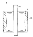
回転子鉄心12の平面形状が、図1に示すように円形の外周部に半円型の凹部14が8個設けられた星型の鋼板を積層しつ加締めることにより製造する。この場合に、回転子鉄心12の軸方向の形状は図2に示すように軸方向の中央部において窪みができるような形状であり、全体形状としては鼓型となる。
The planar shape of the
次に、上記のようにして製造した回転子鉄心12を金型内部に収納し、回転子鉄心12の外周部に各極のフェライト系プラスチックマグネット16を一体成形する。また、回転子鉄心12の中心に回転軸であるシャフト18を貫通させておく。この場合に、図1に示すように各極のプラスチックマグネット16は、端部で連結されたリング状であり、その内周側は凹部14の形状に合わせて、断面形状が中央部が膨らみ端部にいく程細くなる曲面形状、すなわちほぼ半円型となっている。各極のプラスチックマグネット16の外周側の断面形状はシャフト18を中心とした同心円状となっている。
Next, the
なお、金型の内周部は着磁、または、永久磁石が配され、各極のプラスチックマグネット16にS極とN極に交互に着磁させる。
Incidentally, the inner peripheral portion of the mold is magnetized or a permanent magnet is arranged, and the S magnet and the N magnet are alternately magnetized to the
上記のようにして一体成形した回転子10を金型から取り出す。
The
(2)回転子10の効果
上記の回転子10には次のような効果がある。
(2) Effects of
第1の効果としては、従来のリング状のプラスチックマグネットを使用した場合に比べて、各極毎のプラスチックマグネット16の使用量が減り、コストを削減することができる。すなわち、図1に示すように従来の同心円状のリング状のプラスチックマグネットであれば点線20に示すような位置までプラスチックマグネットを用いる必要があったが、本実施形態ではプラスチックマグネット16を凹部14に合わせて曲線状に設けられているため、図1における三角形状の使用量の分だけプラスチックマグネット16の使用量を従来より減らすことができる。
As a first effect, the amount of the
第2の効果としては、回転子鉄心12の外周部に凹部14が設けられ、プラスチックマグネット16がこれに嵌合する形状であるため、回転子鉄心12に対しリング状に連接されたプラスチックマグネット16が回動したりすることがない。すなわち、この凹部14が回り止めの役割を果たしている。
As a second effect, since the
第3の効果としては、回転子鉄心12が鼓型であるため、プラスチックマグネット16が図2における軸方向に抜脱するのを防止することができる。
As a third effect, since the
第4の効果としては、各極のプラスチックマグネット16における内周側の形状が半円型であるため、磁束による着磁波形が正弦波に近くなり、モータの特性が向上する。
As a fourth effect, since the shape on the inner peripheral side of the
(変更例)
本発明は上記実施形態に限らずその趣旨を逸脱しない限り種々に変更することができる。
(Example of change)
The present invention is not limited to the above embodiment, and various modifications can be made without departing from the spirit of the present invention.
(1)変更例1
上記実施形態では回転子鉄心12とプラスチックマグネット16を一体成形したが、これに変えて先ずプラスチックマグネット16のみを成形した後、その中心の空洞部に回転子鉄心12を挿入する製造工程であってもよい。
(1) Modification 1
In the above embodiment, the
(2)変更例2
上記実施形態では、モータとしてブラシレスDCモータを用いたが、これに限らず回転子に永久磁石を用いるものであれば本発明を適用することができ、例えば、単相同期モータの回転子に用いることもできる。
(2) Modification example 2
In the above embodiment, a brushless DC motor is used as the motor. However, the present invention is not limited to this, and any motor that uses a permanent magnet for the rotor can be applied. For example, the motor can be used for a rotor of a single-phase synchronous motor. You can also
本発明のモータの回転子は、ブラシレスDCモータ、単相同期モータ等の回転子に好適である。 The rotor of the motor of the present invention is suitable for a rotor such as a brushless DC motor or a single phase synchronous motor.
10 回転子
12 回転子回転子鉄心
14 凹部
16 プラスチックマグネット
18 シャフト
DESCRIPTION OF
Claims (6)
前記各極のプラスチックマグネットにおける内周側の断面形状が、中央部を膨らませ端部にいくほど細くなる曲面形状であり、
前記各極のプラスチックマグネットがリング状に連結され、
前記回転子鉄心の外周部に前記各極のプラスチックマグネットに対応する凹部が形成されている
ことを特徴とするモータの回転子。 A plastic magnet in which the outer peripheral side of the rotor is magnetized in the S pole and the inner peripheral side is magnetized in the N pole; and a plastic magnet in which the outer peripheral side of the rotor is magnetized in the N pole and the inner peripheral side is magnetized in the S pole; In the rotor of the motor provided alternately on the outer peripheral surface of the rotor core for each pole,
The cross-sectional shape of the inner peripheral side of the plastic magnet of each pole is a curved shape that becomes narrower toward the end by expanding the central part,
The plastic magnet of each pole is connected in a ring shape,
A rotor corresponding to the plastic magnet of each pole is formed on the outer periphery of the rotor core.
ことを特徴とする請求項1記載のモータの回転子。 The motor rotor according to claim 1, wherein a cross-sectional shape of an inner peripheral side of the plastic magnet of each pole is a substantially semicircular shape.
ことを特徴とする請求項1記載のモータの回転子。 The motor rotor according to claim 1, wherein the plastic magnet of each pole and the rotor core are integrally formed.
ことを特徴とする請求項1記載のモータの回転子。 The rotor of a motor according to claim 1, wherein the rotor iron core has a drum shape and has a curved recess in an axial direction of an outer peripheral portion thereof.
ことを特徴とする請求項1記載のモータの回転子。 The motor rotor according to claim 1, wherein the motor is a brushless DC motor.
ことを特徴とする請求項1記載のモータの回転子。 The motor rotor according to claim 1, wherein the motor is a single-phase synchronous motor.
Priority Applications (3)
| Application Number | Priority Date | Filing Date | Title |
|---|---|---|---|
| JP2004111533A JP2005295775A (en) | 2004-04-05 | 2004-04-05 | Motor rotor |
| KR1020050027079A KR100679804B1 (en) | 2004-04-05 | 2005-03-31 | Rotor of motor |
| CN2005100629866A CN1681185B (en) | 2004-04-05 | 2005-04-04 | Brushless DC motor rotor |
Applications Claiming Priority (1)
| Application Number | Priority Date | Filing Date | Title |
|---|---|---|---|
| JP2004111533A JP2005295775A (en) | 2004-04-05 | 2004-04-05 | Motor rotor |
Publications (1)
| Publication Number | Publication Date |
|---|---|
| JP2005295775A true JP2005295775A (en) | 2005-10-20 |
Family
ID=35067653
Family Applications (1)
| Application Number | Title | Priority Date | Filing Date |
|---|---|---|---|
| JP2004111533A Pending JP2005295775A (en) | 2004-04-05 | 2004-04-05 | Motor rotor |
Country Status (3)
| Country | Link |
|---|---|
| JP (1) | JP2005295775A (en) |
| KR (1) | KR100679804B1 (en) |
| CN (1) | CN1681185B (en) |
Cited By (7)
| Publication number | Priority date | Publication date | Assignee | Title |
|---|---|---|---|---|
| JP2007135346A (en) * | 2005-11-11 | 2007-05-31 | Daido Electronics Co Ltd | Yoke integrated magnet |
| US7417347B2 (en) * | 2005-04-11 | 2008-08-26 | Lg Electronics Inc. | Skeleton type BLDC motor |
| JP2013017303A (en) * | 2011-07-04 | 2013-01-24 | Denso Corp | Brushless motor and fuel pump including the same |
| CN103337923A (en) * | 2013-05-18 | 2013-10-02 | 张家港倍恩特磁塑科技有限公司 | Injection moulding permanent magnet rotor of electric tool direct-current high-speed motor |
| JP2017143663A (en) * | 2016-02-10 | 2017-08-17 | シンフォニアテクノロジー株式会社 | Embedded magnet type rotary machine |
| CN109861422A (en) * | 2018-12-04 | 2019-06-07 | 上海大学 | A new type of rotor for high-speed permanent magnet motors |
| US10385863B2 (en) | 2015-06-26 | 2019-08-20 | Denso Corporation | Rotor |
Citations (4)
| Publication number | Priority date | Publication date | Assignee | Title |
|---|---|---|---|---|
| JPS49125209U (en) * | 1973-02-21 | 1974-10-26 | ||
| JPH0576147A (en) * | 1991-09-10 | 1993-03-26 | Fuji Elelctrochem Co Ltd | Rotor for motor |
| JP2002262483A (en) * | 2001-02-27 | 2002-09-13 | Denso Corp | Direct current electronic motor |
| JP2003347142A (en) * | 2002-05-27 | 2003-12-05 | Mitsubishi Electric Corp | Manufacturing method of cylindrical anisotropic magnet and cylindrical anisotropic magnet |
Family Cites Families (2)
| Publication number | Priority date | Publication date | Assignee | Title |
|---|---|---|---|---|
| FR2693854B1 (en) * | 1992-07-16 | 1994-09-30 | Sextant Avionique | Step-by-step engine. |
| GB9611263D0 (en) * | 1995-07-14 | 1996-07-31 | Coin Controls | Inductor |
-
2004
- 2004-04-05 JP JP2004111533A patent/JP2005295775A/en active Pending
-
2005
- 2005-03-31 KR KR1020050027079A patent/KR100679804B1/en not_active Expired - Fee Related
- 2005-04-04 CN CN2005100629866A patent/CN1681185B/en not_active Expired - Fee Related
Patent Citations (4)
| Publication number | Priority date | Publication date | Assignee | Title |
|---|---|---|---|---|
| JPS49125209U (en) * | 1973-02-21 | 1974-10-26 | ||
| JPH0576147A (en) * | 1991-09-10 | 1993-03-26 | Fuji Elelctrochem Co Ltd | Rotor for motor |
| JP2002262483A (en) * | 2001-02-27 | 2002-09-13 | Denso Corp | Direct current electronic motor |
| JP2003347142A (en) * | 2002-05-27 | 2003-12-05 | Mitsubishi Electric Corp | Manufacturing method of cylindrical anisotropic magnet and cylindrical anisotropic magnet |
Cited By (8)
| Publication number | Priority date | Publication date | Assignee | Title |
|---|---|---|---|---|
| US7417347B2 (en) * | 2005-04-11 | 2008-08-26 | Lg Electronics Inc. | Skeleton type BLDC motor |
| JP2007135346A (en) * | 2005-11-11 | 2007-05-31 | Daido Electronics Co Ltd | Yoke integrated magnet |
| JP2013017303A (en) * | 2011-07-04 | 2013-01-24 | Denso Corp | Brushless motor and fuel pump including the same |
| CN103337923A (en) * | 2013-05-18 | 2013-10-02 | 张家港倍恩特磁塑科技有限公司 | Injection moulding permanent magnet rotor of electric tool direct-current high-speed motor |
| US10385863B2 (en) | 2015-06-26 | 2019-08-20 | Denso Corporation | Rotor |
| DE112016002915B4 (en) * | 2015-06-26 | 2025-04-30 | Aisan Kogyo Kabushiki Kaisha | rotor |
| JP2017143663A (en) * | 2016-02-10 | 2017-08-17 | シンフォニアテクノロジー株式会社 | Embedded magnet type rotary machine |
| CN109861422A (en) * | 2018-12-04 | 2019-06-07 | 上海大学 | A new type of rotor for high-speed permanent magnet motors |
Also Published As
| Publication number | Publication date |
|---|---|
| KR20060045356A (en) | 2006-05-17 |
| CN1681185A (en) | 2005-10-12 |
| CN1681185B (en) | 2010-05-12 |
| KR100679804B1 (en) | 2007-02-06 |
Similar Documents
| Publication | Publication Date | Title |
|---|---|---|
| JP5752273B2 (en) | Electric motor | |
| JP5547924B2 (en) | Brushless motor | |
| JP2011024324A5 (en) | ||
| JP6627082B2 (en) | Electric motor | |
| JPH05244741A (en) | Rotor for synchronous motor | |
| JP2007074776A (en) | Rotating electric machine | |
| JP6388066B2 (en) | Brushless motor | |
| JP2009273304A (en) | Rotor of rotating electric machine, and rotating electric machine | |
| KR20140091626A (en) | The spoke type motor | |
| JP2011055577A (en) | Rotor | |
| JP2008278590A (en) | Rotating electric machine | |
| JP2007151293A (en) | motor | |
| JP2011172301A (en) | Motor | |
| CN105656270B (en) | The embedding permanent magnet motor of inexpensive injection-molded for electric power servo steering system | |
| JP2005295775A (en) | Motor rotor | |
| JP2001057753A (en) | Axial gap motor | |
| JP2006288042A (en) | Permanent magnet motor | |
| JP2013207857A (en) | Brushless motor | |
| JP2008029078A (en) | Permanent magnet type synchronous motor | |
| JP2013106499A (en) | Rotary electric machine and rotor of rotary electric machine | |
| JP2006158092A (en) | Rotor of motor | |
| JP2006271142A (en) | Rotating machine | |
| JP2010063277A (en) | Rotor | |
| JPWO2011036723A1 (en) | Synchronous generator | |
| JP6390172B2 (en) | Rotor and motor |
Legal Events
| Date | Code | Title | Description |
|---|---|---|---|
| A621 | Written request for application examination |
Free format text: JAPANESE INTERMEDIATE CODE: A621 Effective date: 20070405 |
|
| A977 | Report on retrieval |
Free format text: JAPANESE INTERMEDIATE CODE: A971007 Effective date: 20100317 |
|
| A131 | Notification of reasons for refusal |
Free format text: JAPANESE INTERMEDIATE CODE: A131 Effective date: 20100323 |
|
| A521 | Request for written amendment filed |
Free format text: JAPANESE INTERMEDIATE CODE: A523 Effective date: 20100515 |
|
| A131 | Notification of reasons for refusal |
Free format text: JAPANESE INTERMEDIATE CODE: A131 Effective date: 20100824 |
|
| A02 | Decision of refusal |
Free format text: JAPANESE INTERMEDIATE CODE: A02 Effective date: 20101221 |