JP2005295730A - Wire harness branch fixing member - Google Patents
Wire harness branch fixing member Download PDFInfo
- Publication number
- JP2005295730A JP2005295730A JP2004109688A JP2004109688A JP2005295730A JP 2005295730 A JP2005295730 A JP 2005295730A JP 2004109688 A JP2004109688 A JP 2004109688A JP 2004109688 A JP2004109688 A JP 2004109688A JP 2005295730 A JP2005295730 A JP 2005295730A
- Authority
- JP
- Japan
- Prior art keywords
- branch
- wire harness
- fixing member
- plate
- branching
- Prior art date
- Legal status (The legal status is an assumption and is not a legal conclusion. Google has not performed a legal analysis and makes no representation as to the accuracy of the status listed.)
- Pending
Links
- 230000001681 protective effect Effects 0.000 claims description 7
- 238000004519 manufacturing process Methods 0.000 abstract description 12
- 239000000463 material Substances 0.000 description 6
- 238000012986 modification Methods 0.000 description 4
- 230000004048 modification Effects 0.000 description 4
- 210000000078 claw Anatomy 0.000 description 3
- 238000005259 measurement Methods 0.000 description 3
- 238000004804 winding Methods 0.000 description 3
- 238000000034 method Methods 0.000 description 2
- 229920005989 resin Polymers 0.000 description 2
- 239000011347 resin Substances 0.000 description 2
- 239000004743 Polypropylene Substances 0.000 description 1
- 239000000853 adhesive Substances 0.000 description 1
- 230000001070 adhesive effect Effects 0.000 description 1
- 239000002390 adhesive tape Substances 0.000 description 1
- 230000000712 assembly Effects 0.000 description 1
- 238000000429 assembly Methods 0.000 description 1
- 230000001276 controlling effect Effects 0.000 description 1
- 238000010586 diagram Methods 0.000 description 1
- 238000006073 displacement reaction Methods 0.000 description 1
- 239000000428 dust Substances 0.000 description 1
- 230000000694 effects Effects 0.000 description 1
- 238000001746 injection moulding Methods 0.000 description 1
- 230000002093 peripheral effect Effects 0.000 description 1
- 239000011295 pitch Substances 0.000 description 1
- -1 polypropylene Polymers 0.000 description 1
- 229920001155 polypropylene Polymers 0.000 description 1
- 230000001105 regulatory effect Effects 0.000 description 1
- 229920003002 synthetic resin Polymers 0.000 description 1
- 239000000057 synthetic resin Substances 0.000 description 1
Images

Landscapes
- Details Of Indoor Wiring (AREA)
Abstract
【課題】ワイヤーハーネスの分岐部の分岐位置を精度良く容易に製作することに供されるワイヤーハーネス分岐部固定部材を提供すること。
【解決手段】ワイヤーハーネスの分岐位置に取り付けてワイヤーハーネスを固定する固定部材であって、ワイヤーハーネスの分岐形状に対応して枝分かれ形成された複数の枝部を有するプレートから成り、少なくとも該プレートの枝分かれ位置には開口穴が形成されている。
【選択図】図2An object of the present invention is to provide a wire harness branching portion fixing member that is used to easily and accurately manufacture a branching position of a branching portion of a wire harness.
A fixing member that is attached to a branch position of a wire harness and fixes the wire harness, and includes a plate having a plurality of branch portions that are branched and formed corresponding to the branch shape of the wire harness. An opening hole is formed at the branching position.
[Selection] Figure 2
Description
本発明は、自動車に配索されるワイヤーハーネスに関し、更に詳しくは、このワイヤーハーネスの分岐位置に取り付けてワイヤーハーネスを固定する固定部材に関するものである。 The present invention relates to a wire harness routed in an automobile, and more particularly to a fixing member that is attached to a branch position of the wire harness and fixes the wire harness.
一般に、自動車のエンジンルームや室内等に配索されるケーブルの束よりなるワイヤハーネスにおいては、ケーブルを熱や埃から保護するとともに、振動等による周辺部品との接触を防止するために、テーピングや、コルゲートチューブ、スパイラルチューブなどの筒状のチューブ材により外装されている。 In general, in a wire harness composed of a bundle of cables routed in the engine room or room of an automobile, the cable is protected from heat and dust, and in order to prevent contact with peripheral parts due to vibrations, taping and It is covered with a tubular tube material such as a corrugated tube or a spiral tube.
例えば、コルゲートチューブは、耐衝撃性や耐摩耗性に優れたポリプロピレン樹脂等の合成樹脂材料により成形されたもので、薄肉円筒状に形成され、周方向の凹溝と凸条とを交互にチューブ長さ方向に等ピッチで配した蛇腹構造を有した屈曲性に富むもので、内部にケーブルの束を収容して保護する。このコルゲートチューブには、長手方向に切り込みが設けられたものとそうでないものとがあり、切り込みのあるものはその口開きによりケーブルの収容が容易であるところから広く使われている。 For example, a corrugated tube is formed of a synthetic resin material such as polypropylene resin excellent in impact resistance and wear resistance, and is formed into a thin cylindrical shape, and is formed by alternately forming circumferential grooves and ridges. It has a flexible structure with a bellows structure arranged at equal pitches in the length direction, and accommodates and protects a bundle of cables inside. This corrugated tube has a notch in the longitudinal direction and a notch in the corrugated tube, and the notched one is widely used because the cable can be easily accommodated by opening the mouth.
自動車等に使用されているワイヤーハーネスは車体の各所に配索され所要位置で分岐されて、車体に設置されている各機器に接続されているが、ワイヤーハーネスの分岐位置ではこのようなチューブ材も分割する必要があり、その結果、分割場所に隙間が生じ、テープ等を巻き付けて分割箇所の防水および保護等を図る必要がある。 Wire harnesses used in automobiles, etc. are routed at various locations on the car body, branched at the required position, and connected to each device installed on the car body. Need to be divided, and as a result, a gap is generated at the divided place, and it is necessary to wrap the tape or the like to waterproof and protect the divided portion.
図7は、複数本のケーブルWaを束ねて本線Wbから分岐された枝線Wcを有して、その枝線Wcの端末部分に電気機器や各種センサ等への接続のためのコネクタCを備えたワイヤーハーネスWが示されている。図示されるようにコルゲートチューブTが枝線Wcやその他の部分において外装されている。 FIG. 7 shows a branch line Wc branched from the main line Wb by bundling a plurality of cables Wa, and a terminal C of the branch line Wc is provided with a connector C for connection to electrical equipment, various sensors, and the like. A wire harness W is shown. As shown in the figure, a corrugated tube T is sheathed at the branch line Wc and other portions.
このようなワイヤーハーネスWは、自動車に取り付けた際に先端のコネクタCが、接続の相手となる電気機器のコネクタに対して所望の位置となるように、ケーブルWaの長さやこれに外装されるコルゲートチューブTの長さを厳密に寸法管理して製作されている。コルゲートチューブTの端部から露出した部分は、コルゲートチューブTのケーブルWaに対する遊動を許容しないように、粘着テープを巻いて固定される。これらアッセンブリーはワイヤーハーネス製作図板上にて行われ、特に分岐位置は、図板に固定された棒状の治具に載置されて行われる。そして、アッセブリーされたワイヤーハーネスWを自動車内部に作業者が配索してコネクタ接続等を行っている。 Such a wire harness W is externally attached to the length of the cable Wa or the like so that the connector C at the distal end is in a desired position with respect to the connector of the electrical device to be connected when attached to the automobile. The corrugated tube T is manufactured by strictly controlling the length of the corrugated tube T. The portion exposed from the end of the corrugated tube T is fixed by winding an adhesive tape so as not to allow the corrugated tube T to move with respect to the cable Wa. These assemblies are performed on the wire harness production drawing board, and in particular, the branch position is placed on a bar-shaped jig fixed to the drawing board. Then, an operator wires the assembled wire harness W inside the automobile to perform connector connection and the like.
このようなワイヤーハーネスWの分岐位置や枝線Wc長さは、先端のコネクタCが接続の相手の電気機器のコネクタの位置に対して、長すぎたり、短かすぎたりすると接続作業が煩雑になることことから、寸法管理されて製作されるのであるが、図示されるように分岐の中心が分かりづらいため、寸法測定時の測定点が定まらず結果寸法精度が出ないという問題がある。また、分岐位置のテーピングは、ハーネスを一旦製作図板の治具から外して行うため、この際に分岐位置がずれてしまうことがある。更に、テーピングだけの固定だけでは、分岐位置や分岐の方向を規制し難いという問題、また、テープの巻き方次第で分岐部の形状、大きさが変わってしまうという問題があった。このようなことから製造公差の管理が難しく、設計寸法通りにワイヤーハーネスを作ることが困難であった。 Such a branch position and the length of the branch line Wc of the wire harness W are complicated if the tip connector C is too long or too short with respect to the position of the connector of the electrical device to be connected. As a result, it is manufactured under dimensional control. However, since the center of the branch is difficult to understand as shown in the figure, there is a problem that the measurement point at the time of dimensional measurement is not determined and the dimensional accuracy is not obtained as a result. Further, taping at the branch position is performed by once removing the harness from the jig of the production drawing board, and the branch position may be shifted at this time. Furthermore, there is a problem that it is difficult to regulate the branch position and the branch direction only by fixing the taping, and there is a problem that the shape and size of the branch part change depending on the winding method of the tape. For these reasons, it is difficult to manage manufacturing tolerances, and it is difficult to make a wire harness according to the design dimensions.
そこで、本発明が解決する課題は、ワイヤーハーネスの分岐部の分岐位置を精度良く容易に製作することに供されるワイヤーハーネス分岐部固定部材を提供することである。 Then, the subject which this invention solves is providing the wire harness branch part fixing member with which it uses for manufacturing easily the branch position of the branch part of a wire harness accurately.
この課題を解決するため本発明は、ワイヤーハーネスの分岐位置に取り付けてワイヤーハーネスを固定する固定部材であって、前記ワイヤーハーネスの分岐形状に対応して枝分かれ形成された複数の枝部を有するプレートから成り、少なくとも該プレートの枝分かれ位置には開口穴が形成されていることを要旨とするものである。 In order to solve this problem, the present invention is a fixing member that is attached to a branch position of a wire harness and fixes the wire harness, and a plate having a plurality of branch portions formed to branch according to the branch shape of the wire harness The gist is that an opening hole is formed at least at the branching position of the plate.
この場合において、前記枝部は可撓可能であると良い。また、前記枝部には枝方向に対して側方に段部が形成されていると良い。更には、前記プレートの開口穴近傍には保護壁が設けられていると良い。そして、前記枝部にはコルゲートチューブと嵌合するコルゲート嵌合部材が別途取り付けられていると良い。 In this case, the said branch part is good to be flexible. Further, it is preferable that a step portion is formed on the branch portion laterally with respect to the branch direction. Furthermore, a protective wall may be provided in the vicinity of the opening hole of the plate. And it is good for the said branch part to attach separately the corrugated fitting member fitted with a corrugated tube.
上記構成を有するワイヤーハーネス分岐部固定部材によれば、ワイヤーハーネスの分岐形状に対応して枝分かれ形成された複数の枝部を有するプレートから成り、そのプレートの枝分かれ位置には開口穴が形成されているので、この開口穴に例えばハーネス製作図板の棒状の治具を挿通させて、これを中心に分岐部を形成すれば、分岐位置が明確になって寸法測定が行い易くなり、その結果寸法精度が向上する。また、プレートの枝部は、ケーブルや外装材をテーピング等で直接固定することに利用できるので、分岐位置や分岐の方向を規制することができ、更には、分岐部の形状・大きさを一定のものにすることもできる。これにより製造公差の管理が容易になり、設計寸法通りにワイヤーハーネスを作ることが可能になる。 According to the wire harness branching portion fixing member having the above-described configuration, the wire harness branching portion fixing member includes a plate having a plurality of branching portions formed corresponding to the branching shape of the wire harness, and an opening hole is formed at the branching position of the plate. Therefore, for example, if a rod-shaped jig of a harness production drawing board is inserted into this opening hole and a branch part is formed around this hole, the branch position becomes clear and dimension measurement can be performed easily. Accuracy is improved. In addition, the plate branch can be used for directly fixing cables and exterior materials by taping, etc., so that the branch position and branch direction can be regulated, and the shape and size of the branch are constant. Can also be This facilitates the management of manufacturing tolerances and makes it possible to produce a wire harness according to the design dimensions.
この場合、前記枝部は可撓可能であるという構成にすれば、例えば、テープを巻く枝部を可撓させながら下巻き1〜2回後、枝部を戻してケーブルや外装材と一緒にテープ巻きをすることができるので、テーピングのために一旦製作図板の治具から外す必要がなくなる。また、前記枝部には枝方向に対して側方に段部が形成されているという構成にすれば、テープや結束バンドを強固に固定してプレートからのズレが防止される。更に、前記プレートの開口穴近傍には保護壁が設けられているという構成にすれば、分岐部のケーブルの保護性能が向上すると共に、テープレス化も可能となる。 In this case, if the branch portion is configured to be flexible, for example, the lower branch is wound once or twice while the branch portion around which the tape is wound is flexed, and then the branch portion is returned together with the cable and the exterior material. Since the tape can be wound, it is not necessary to remove it once from the jig of the production drawing board for taping. Further, if the branch portion is formed with a step portion laterally with respect to the branch direction, the tape and the binding band are firmly fixed to prevent displacement from the plate. Further, if a protective wall is provided in the vicinity of the opening hole of the plate, the protection performance of the cable at the branching portion can be improved and tapeless can be realized.
そして、前記枝部にはコルゲートチューブと嵌合するコルゲート嵌合部材が別途取り付けられているという構成にすれば、特許文献1や特許文献2に記載のような、コルゲートチューブに対応した分岐部専用の継ぎ手を用いなくても、プレートとコルゲート嵌合部材を分けた事により、コルゲートチューブのサイズに制限されることがないので、汎用性があり、安価でもある。
And if it is set as the structure that the corrugated fitting member fitted to a corrugated tube is separately attached to the said branch part, it is only for the branch part corresponding to a corrugated tube like
以下に、本発明に係るワイヤーハーネス分岐部固定部材の実施の形態について図面を参照して説明する。 Embodiments of a wire harness branching portion fixing member according to the present invention will be described below with reference to the drawings.
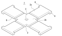
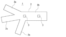
図1は本発明に係るワイヤーハーネス分岐部固定部材1の概略構成を説明した図である。図1は、ワイヤーハーネスのケーブルが配されるプレート2を示している。このプレート2は、可撓性を有する樹脂製の板材の打ち抜き加工又は射出成形等により成形されたもので、ワイヤーハーネスの分岐部の形状に合せて同じく所定位置で分岐された枝部2とその基部2bを備えており、ハーネス配索場所での配索状態等を考慮した形状・大きさを有してる。
FIG. 1 is a diagram illustrating a schematic configuration of a wire harness branching
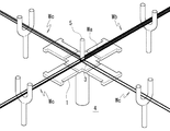
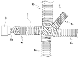
このプレート2の各枝部2aの枝分かれ位置には、つまり基部2bのほぼ中央には開口穴3がこの場合1つ形成されている。この開口穴3は、図2に示すようなハーネス製作図板4上に設けられた棒状の治具5が挿入されるもので、図示されるようにケーブルWaは、これを中心に本線Wb、枝線Wcへと分岐して配されている。このようにすれば、分岐の中心位置が明確になって、分岐位置から端末のコネクタまでの寸法測定が行い易くなり、その結果寸法精度が向上する。
In this case, one
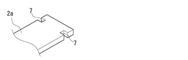
また、各枝部2aの先端には、分岐方向に対して側方に突出した段部6が形成されており、ケーブルやコルゲートチューブなどの外装材をテープや結束バンドで固定した際、それらと枝部2aとのズレを防止するためのものである。この場合、図3に示すように、枝部2a先端の一部を側方に凹設させた形状の段部7としても同様の効果がある。
Further, at the tip of each
更に、各枝部2aの途中位置には、薄肉部8が形成されており、枝部2aの上下の可撓を容易にしている。このように枝部2aに可撓性を持たせることで、例えば、ケーブルWaを枝部2aにテーピングで固定する際、テープを巻く枝部2aを一旦下へ可撓させながら直接ケーブルWaに下巻き1〜2回後、枝部2aを戻してケーブルWaと一緒にテープ巻きをすることができる。これにより、従来テーピングのために一旦製作図板の治具から分岐部を外すという作業が無くなり、外した際に分岐位置がずれてしまうという問題が解消される。
Furthermore, a
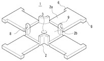
次に、上述したワイヤーハーネス分岐部固定部材に係るプレート2の変形例について説明する。図4に示すプレート2には、開口穴3を囲むように側壁となる保護壁9が形成されている。このように開口穴3の近傍に保護壁9を設ければ、この分岐位置のケーブルの保護性能が向上すると共に、この部分のテープレス化も可能となる。この場合、この保護壁9上面を覆うように別途蓋部材で閉じた構成にしても良く、その場合は更に保護性能が向上する。
Next, the modification of the
図5に示すワイヤーハーネス分岐部固定部材は、特にコルゲートチューブTに好適に用いられるもので、プレート2の各枝部2aには、係合穴10が形成されており、図示されるコルゲート嵌合部材11の下面に設けられた図示しない係合爪が係合して、容易に外れないように取り付けられるようになっている。
The wire harness branching portion fixing member shown in FIG. 5 is particularly preferably used for the corrugated tube T, and each
このコルゲート嵌合部材11は、上方が開口したU字形状を有しており、内側の嵌合爪11aは、図示されるコルゲートチューブTの蛇腹の溝に嵌合するようになっている。このように、プレート2にコルゲート嵌合部材11を取り付ける構成にすることにより、種々なるサイズのコルゲート嵌合部材11を用意すれば、プレート2を変更することなく対応できる。つまり、コルゲートチューブのサイズに制限されることがないので、汎用性があり、安価なワイヤーハーネス分岐部固定部材である。
The
以上詳述したように、本発明に係るワイヤーハーネス分岐部固定部材は、ワイヤーハーネスの分岐部の分岐位置を精度良く容易に製作することに供されるものであり、こうした実施形態に何ら限定されるものではなく、本発明の要旨を逸脱しない範囲において、種々なる態様で実施できることは勿論である。 As described above in detail, the wire harness branching portion fixing member according to the present invention is used for easily and accurately manufacturing the branching position of the branching portion of the wire harness, and is not limited to such an embodiment. Of course, the present invention can be implemented in various forms without departing from the gist of the present invention.
例えば、プレート2の形状は、図6に示されるように、ワイヤーハーネスの実際の配索状態に合せて種々なる形状・長さ・断面構造を採用することができ、実施例のような形状には限定されないことはいうまでもない。また、開口穴3も図示されるように、角形状でも良く、個数も制限されない。更に、コルゲート嵌合部材11のプレート2の枝部2aへの取り付けについても、上述した係合構造には限定されず、接着剤を用いたりなど種々なる取り付け方法が適用される。
For example, as shown in FIG. 6, the shape of the
1 ワイヤーハーネス分岐部固定部材
2 プレート
2a 枝部
2b 基部
3 開口穴
4 ハーネス製作図板
5 治具
6,7 段部
8 薄肉部
9 保護壁
10 係合穴
11 コルゲート嵌合部材
11a 嵌合爪
W ワイヤーハーネス
Wa ケーブル
Wb 本線
Wc 枝線
DESCRIPTION OF
Claims (5)
Priority Applications (1)
| Application Number | Priority Date | Filing Date | Title |
|---|---|---|---|
| JP2004109688A JP2005295730A (en) | 2004-04-02 | 2004-04-02 | Wire harness branch fixing member |
Applications Claiming Priority (1)
| Application Number | Priority Date | Filing Date | Title |
|---|---|---|---|
| JP2004109688A JP2005295730A (en) | 2004-04-02 | 2004-04-02 | Wire harness branch fixing member |
Publications (1)
| Publication Number | Publication Date |
|---|---|
| JP2005295730A true JP2005295730A (en) | 2005-10-20 |
Family
ID=35328049
Family Applications (1)
| Application Number | Title | Priority Date | Filing Date |
|---|---|---|---|
| JP2004109688A Pending JP2005295730A (en) | 2004-04-02 | 2004-04-02 | Wire harness branch fixing member |
Country Status (1)
| Country | Link |
|---|---|
| JP (1) | JP2005295730A (en) |
Cited By (2)
| Publication number | Priority date | Publication date | Assignee | Title |
|---|---|---|---|---|
| JP2012242667A (en) * | 2011-05-20 | 2012-12-10 | Sumitomo Wiring Syst Ltd | Routing structure of wire harness |
| JP2015082883A (en) * | 2013-10-22 | 2015-04-27 | 住友電装株式会社 | Band clip attachment structure to corrugated tube |
-
2004
- 2004-04-02 JP JP2004109688A patent/JP2005295730A/en active Pending
Cited By (4)
| Publication number | Priority date | Publication date | Assignee | Title |
|---|---|---|---|---|
| JP2012242667A (en) * | 2011-05-20 | 2012-12-10 | Sumitomo Wiring Syst Ltd | Routing structure of wire harness |
| JP2015082883A (en) * | 2013-10-22 | 2015-04-27 | 住友電装株式会社 | Band clip attachment structure to corrugated tube |
| WO2015060079A1 (en) * | 2013-10-22 | 2015-04-30 | 住友電装株式会社 | Corrugated-tube band-clip mounting structure |
| US9539959B2 (en) | 2013-10-22 | 2017-01-10 | Sumitomo Wiring Systems, Ltd. | Structure for attaching band clip to corrugated tube |
Similar Documents
| Publication | Publication Date | Title |
|---|---|---|
| JP6212329B2 (en) | Exterior member | |
| JP5668617B2 (en) | Corrugated tube with path maintenance member and wire harness | |
| JP2006311785A (en) | Protector | |
| AU701830B2 (en) | Electrical connection box assembly with tapered projection | |
| JP2018156943A (en) | Cable harness plug | |
| JP5950793B2 (en) | Wire harness | |
| US9343889B2 (en) | Electric wire fixing device | |
| JP5394824B2 (en) | Electrical junction box | |
| JP2012110100A (en) | Wire harness | |
| JP2009055740A (en) | Wire harness to which protective member is attached and method for manufacturing the protective member | |
| JP4138429B2 (en) | Manufacturing method of wire harness | |
| JP2005295730A (en) | Wire harness branch fixing member | |
| JP2009055726A (en) | Fixed structure for linear objects | |
| JP2009136107A (en) | Protection member | |
| JP5215201B2 (en) | Grommet | |
| KR200378967Y1 (en) | Wire harness fix clip | |
| JP6117405B2 (en) | Wire harness | |
| JP5607133B2 (en) | Fixed structure for linear objects | |
| JP7560513B2 (en) | Wire harness manufacturing method, wire harness, protective member assembly, and protective member | |
| JP2007185067A (en) | Flexible cable protection tube | |
| JP2013089439A (en) | Wire harness, and insulation cover member | |
| JP3143262U (en) | Assembly jig for wire harness | |
| JP2004274951A (en) | Wiring harness wiring structure | |
| JP5892578B2 (en) | Wire harness | |
| JP2004289931A (en) | Stretch restriction structure of wire harness |