JP2005295699A - Metal graphite brush - Google Patents
Metal graphite brush Download PDFInfo
- Publication number
- JP2005295699A JP2005295699A JP2004107650A JP2004107650A JP2005295699A JP 2005295699 A JP2005295699 A JP 2005295699A JP 2004107650 A JP2004107650 A JP 2004107650A JP 2004107650 A JP2004107650 A JP 2004107650A JP 2005295699 A JP2005295699 A JP 2005295699A
- Authority
- JP
- Japan
- Prior art keywords
- brush
- metal
- graphite brush
- corrosion resistance
- metal graphite
- Prior art date
- Legal status (The legal status is an assumption and is not a legal conclusion. Google has not performed a legal analysis and makes no representation as to the accuracy of the status listed.)
- Pending
Links
Images
Landscapes
- Motor Or Generator Current Collectors (AREA)
- Powder Metallurgy (AREA)
- Manufacture Of Alloys Or Alloy Compounds (AREA)
Abstract
【課題】 硫黄やその化合物が混ざった各種の内燃機関の燃料や、蟻酸,酢酸等の有機酸が混ざった燃料に対しても、耐食性に優れた金属黒鉛ブラシを提供する。
【解決手段】 黒鉛粉末と金属粉末とを含む原料粉末を加圧して圧粉体を形成し、この圧粉体を焼結してなる金属黒鉛ブラシ2において、質量で、Cu:4〜53%、Ni:1.5〜22%、Sn:0.5〜11%、を含有するから、強度と共に、硫黄やその化合物に対する耐食性と蟻酸や酢酸等の有機酸に対する耐食性の両者を備えた金属黒鉛ブラシが得られる。
【選択図】 図1PROBLEM TO BE SOLVED: To provide a metal graphite brush excellent in corrosion resistance against various internal combustion engine fuels mixed with sulfur and its compounds and fuels mixed with organic acids such as formic acid and acetic acid.
SOLUTION: In a metal graphite brush 2 formed by pressing a raw material powder containing graphite powder and metal powder to form a green compact, and sintering the green compact, Cu: 4 to 53% by mass. , Ni: 1.5-22%, Sn: 0.5-11%, so that it has both strength, corrosion resistance to sulfur and its compounds and corrosion resistance to organic acids such as formic acid and acetic acid A brush is obtained.
[Selection] Figure 1
Description
本発明は、耐食性を備えた金属黒鉛ブラシに関する。 The present invention relates to a metal graphite brush having corrosion resistance.
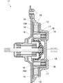
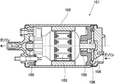
従来、内燃機関の一例であるガソリンエンジンで、図8に示すようなモータ式燃料ポンプが用いられている。すなわち、図示される通り上記燃料ポンプ101は、ケーシング102内において、モータ103の両端部に固設した回転軸104が軸受105に支持され、前記回転軸104の一方端部にはインペラ106が挿入され、かつ前記インペラ106、モータ103(アーマチュア)の外周面、および軸受105と回転軸104との間の図示しない隙間に沿って狭い間隙のガソリン流通路(図示せず)が形成された構造を有し、前記モータ103の回転でインペラ106が回転し、このインペラ106の回転でガソリンがケーシング102内に取り込まれ、取り込まれたガソリンはインペラ106、モータ103の外周面、および軸受105と回転軸104との間の図示しない隙間に沿って形成されたガソリン流通路を通って送り出され、別設のガソリンエンジンに送り込まれるように作動するものであり、前記燃料ポンプ101は燃料タンク内で使用される。
Conventionally, a motor type fuel pump as shown in FIG. 8 is used in a gasoline engine which is an example of an internal combustion engine. That is, as shown in the figure, in the
上記のように燃料ポンプ101のモータ103や燃料タンクの近傍で用いられるモータは、燃料の影響を受けるため、通常の使用条件よりは耐食性を考慮したものを使用する必要があり、例えばモータに使用されるブラシは耐久性が低下する場合がある。特に、硫黄やその化合物が混ざった燃料や、蟻酸や酢酸等の有機酸が混ざった燃料を使用する場合、これらに対する耐食性を確保しないと、腐食により寿命が低下する問題がある。
As described above, the
そこで、小型モータのブラシ装置において、整流子との摺接面の部分以外の導電パターンは、グリーンレジスト等の絶縁皮膜が施され、非レジスト部には、金メッキ等の絶縁被膜が施され、非レジスト部には、金メッキ等の貴金属メッキによる酸化防止膜が施され、摺接面を形成し、前記メッキによる効果は、導電パターンの表面の酸化防止と、動作時における磨耗対策としての役目をなし(例えば特許文献1)、また、モータ用ブラシであって、連続気孔を有する発泡金属から成る導電体を炭素粉末、黒鉛粉末等のように固有抵抗の大きい黒鉛質粉末とともに所定の形状及び寸法に一体成形したのち、焼成することによって焼結し、前記導電体の表面に銀、金、白金、パラジウム、錫等のような固有抵抗の小さい導電性金属の被膜をメッキ、その他の方法で形成する(例えば特許文献2)ようにしたものが知られている。
上記のようにモータ部品であるブラシに金メッキ等の金被覆層を施すことにより、耐食性の向上を図ることができるが、メッキやその他の方法を用いる場合でも、金被覆層を設けるにはコストが掛かる問題がある。また、金メッキは比較的柔らかいため、組立て作業中に外部に接触すると、接触した部分の耐食性が低下することが懸念される。 As described above, by applying a gold coating layer such as gold plating to the brush which is a motor component, it is possible to improve the corrosion resistance. However, even when plating or other methods are used, it is costly to provide the gold coating layer. There is a problem. In addition, since gold plating is relatively soft, there is a concern that the corrosion resistance of the contacted portion may be reduced if it contacts the outside during assembly work.
本発明は、このような問題点を解決しようとするもので、硫黄やその化合物が混ざった各種の内燃機関の燃料や、蟻酸,酢酸等の有機酸が混ざった燃料に対しても、耐食性に優れた金属黒鉛ブラシを提供することを目的とする。 The present invention is intended to solve such problems, and is resistant to corrosion even for fuels of various internal combustion engines mixed with sulfur and its compounds and fuels mixed with organic acids such as formic acid and acetic acid. An object is to provide an excellent metal graphite brush.
請求項1の金属黒鉛ブラシは、黒鉛粉末と金属粉末とを含む原料粉末を加圧して圧粉体を形成し、この圧粉体を焼結してなる金属黒鉛ブラシにおいて、質量で、Cu:4〜53%、Ni:1.5〜22%、Sn:0.5〜11%、を含有するものである。
The metal graphite brush according to
また、請求項2の金属黒鉛ブラシは、質量で、Zn:0.5〜11%、MoS2:0.5〜3%、を含有するものである。
The metal graphite brush of
また、請求項3の金属黒鉛ブラシは、外面を被覆する被覆層を備え、この被覆層が四フッ化エチレン樹脂層であるものである。 According to a third aspect of the present invention, the metal graphite brush includes a coating layer that covers an outer surface, and the coating layer is a tetrafluoroethylene resin layer.
請求項1の構成によれば、強度と共に、硫黄やその化合物に対する耐食性と蟻酸や酢酸等の有機酸に対する耐食性の両者を備えた金属黒鉛ブラシが得られ、Niは、Cuに固溶して、Cu−Ni系合金などの固溶体相からなる素地を形成し、強度及び耐食性を向上させる作用があるが、その含有量が1.5%未満では耐食性が不足し、22%を超えると、強度が不足するようになるので、含有量を1.5〜22%、好ましくは3〜18%である。また、Snは、その含有量が0.5%未満では耐食性が不足し、11%を超えると、強度が不足するようになるので、含有量を0.5〜11%、好ましくは2〜9%である。
According to the configuration of
また、請求項2の構成によれば、Cu−Ni−Zn系合金の固溶体相からなる素地を形成し、Znは、強度に貢献し、その含有量が0.5%未満では強度の向上効果がなく、11%を超えると、強度が不足するようになるので、含有量を0.5〜11%、好ましくは2〜9%である。また、MoS2(二硫化モリブデン)は、潤滑性を付与し、その含有量が0.5%未満では潤滑性の効果がなく、3%を超えると、強度が不足するようになるので、含有量を0.5〜3%、好ましくは1〜2%である。
Moreover, according to the structure of
また、請求項3の構成によれば、耐食性が一層向上する。
Moreover, according to the structure of
本発明における好適な実施の形態について、添付図面を参照しながら詳細に説明する。なお、以下に説明する実施の形態は、特許請求の範囲に記載された本発明の内容を限定するものではない。また、以下に説明される構成の全てが、本発明の必須要件であるとは限らない。各実施例では、従来とは異なる金属黒鉛ブラシを採用することにより、従来にない金属黒鉛ブラシが得られ、その金属黒鉛ブラシを夫々記述する。 Preferred embodiments of the present invention will be described in detail with reference to the accompanying drawings. The embodiments described below do not limit the contents of the present invention described in the claims. In addition, all of the configurations described below are not necessarily essential requirements of the present invention. In each embodiment, by using a metal graphite brush different from the conventional one, an unprecedented metal graphite brush is obtained, and the metal graphite brush is described respectively.
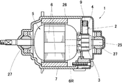
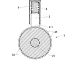
以下、本発明の金属黒鉛ブラシの実施例1について、図1〜図4を参照しながら説明する。同図において、モータ1と、金属黒鉛ブラシ2及び整流子3などを示している。前記整流子3は、モータ1の回転軸25に設けられ、相互に絶縁された複数の整流子片3A,3A,3A…を備え、回転軸25に設けた回転子5にコイル6,6,6…を設け、これらコイル6,6,6…を構成するリード線6Rの端部を前記整流子片3A,3A,3A…に接続しており、ブラシ2に電源を接続して整流子3を介して給電することにより、前記コイル6,6,6…と固定マグネット7との間でトルクが発生し、回転子5を回転付勢するようにしている。尚、図中26はモータ1のケーシングであり、27は回転軸25を回転自在に支持する軸受である。
Hereinafter, Example 1 of the metal graphite brush of the present invention will be described with reference to FIGS. In the figure, a
図2に示すように、前記金属黒鉛ブラシ2は、黒鉛粉末と金属粉末などを混合した原料粉末を加圧して圧粉体を形成し、この圧粉体を焼結してなる焼結合金からなる。この焼結合金の製造方法につき説明すると、原料粉末として黒鉛粉末と金属粉末とを所定の割合で混合する。金属粉末は、例えば、Cu−Ni合金、Cu−Ni−Zn合金、Cu−Ni−Zn−Sn合金などを用いることができ、質量%で、Cu:4〜53%、Ni:1.5〜22%、Sn:0.5〜11%、Zn:0.5〜11%、MoS2:0.5〜3%、を含有する。そして、残りがCと不可避不純物からなる組成のものを用いることができる。特に好ましくは、質量%で、Cu:10〜45%、Ni:3〜18%、Sn:2〜9%、Zn:2〜9%、MoS2:1〜2%、を含有し、残りがCと不可避不純物とする。すなわち、Niは、Cuに固溶して、Cu−Ni系合金の固溶体相からなる素地を形成し、強度及び耐食性を向上させる作用があるが、その含有量が1.5%未満では耐食性が不足し、22%を超えると、強度が不足するようになるので、含有量を1.5〜22%、好ましくは3〜18%である。また、Snは、その含有量が0.5%未満では耐食性が不足し、11%を超えると、強度が不足するようになるので、含有量を0.5〜11%、好ましくは2〜9%である。また、Znは、強度に貢献し、その含有量が0.5%未満では強度の向上効果がなく、11%を超えると、強度が不足するようになるので、含有量を0.5〜11%、好ましくは2〜9%である。また、MoS2(二硫化モリブデン)は、潤滑性を付与し、その含有量が0.5%未満では潤滑性の効果がなく、3%を超えると、強度が不足するようになるので、含有量を0.5〜3%、好ましくは1〜2%である。
As shown in FIG. 2, the
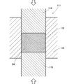
そして、原料粉末を成形金型111の充填部115に充填する。図3は成形金型111の一例を示し、この成形金型111は、上下方向を軸方向(プレス上下軸方向)としており、ダイ112、下パンチ113および上パンチ114を備えている。下パンチ113は、ほぼ角柱形状で、ダイ112に下方から上下動自在に嵌合している。上パンチ114は、ほぼ角柱形状で、ダイ112に上方から上下動自在にかつ挿脱自在に嵌合するものである。そして、ダイ112と下パンチ113との間に前記充填部115が形成される。この充填部115に、原料粉末を充填し、これらに振動を与える。この後、下,上パンチ113,114により充填部115内の原料粉末を加圧することにより圧粉体2Aを成形する。この圧粉体2Aを焼結することにより、前記金属黒鉛ブラシ2が形成される。
実験例
比較例の金属黒鉛ブラシは、質量で、Cu:10〜80%、Sn:1〜10%、を含有し、残りをCと不可避不純物からなる組成の原料粉末を用い、この原料粉末を加圧して圧粉体を形成し、この圧粉体を焼結してなる。この比較例のものと、実施例(後述する被覆層はなし)のものを用いたモータ1で、酢酸600ppm、蟻酸と酢酸1000ppm、アルコール5000ppm含むガソリンを使用して試験を行ったところ、比較例のものは数時間で腐食が原因によるガジリを発生し、使用不能となったのに対して、実施例のものは1000時間の耐久性が得られた。
Then, the raw material powder is filled into the filling
Experimental Example The metal graphite brush of the comparative example contains Cu: 10 to 80%, Sn: 1 to 10% by mass, and the raw material powder having a composition composed of C and inevitable impurities is used. A green compact is formed by pressing, and the green compact is sintered. The
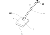
また、金属黒鉛ブラシ2の表面に、四フッ化エチレン樹脂により被覆層を形成してもよく、好ましい四フッ化エチレン樹脂層8の厚さは5〜15μmである。そして、前記複数の導電線を撚って撚り線22を形成し、該撚り線22に金属黒鉛ブラシ2と端子接続部23を接続して組み立てた後、撚り線22、該撚り線22と金属黒鉛ブラシ2との接続箇所22S及び端子接続部23の露出した外面に、被覆層である四フッ化エチレン樹脂層8を形成する。尚、四フッ化エチレン樹脂として、例えばPTFE(テフロン(登録商標))を用いることができる。
Moreover, you may form a coating layer with the tetrafluoroethylene resin on the surface of the
尚、各導電線に四フッ化エチレン樹脂層8をコーティングした後、撚って撚り線22としてもよく、この場合は必ずしも撚り線22にコーティングする必要はない。また、前記接合箇所22Sは半田などにより構成される。
In addition, after coating the
前記四フッ化エチレン樹脂層8は、四フッ化エチレン樹脂をコーティングして形成される。まず、コーティングを施すコーティング面には、バリ、錆などがないものとし、これを確認する。次に、必要に応じて、脱脂後、好ましくは燐酸塩処理等の化学処理、又はブラスト等で洗浄化し、密着性をよくする。続いて、温風などで速やかに乾燥処理するか、有機溶剤で洗浄脱脂をし乾燥させる。コーティングの方法には、スプレー法、浸漬法、刷毛塗布法などを用いることができ、刷毛を用いて塗る刷毛塗布法が簡易である。また、全体にコーティングを施すにはタンブラー法も好適である。尚、コーティングに用いる四フッ化エチレン樹脂は、溶剤以外ほぼ100%同樹脂を用いる。また、コーティング後は常温で焼成する。
The
また、整流子3及び前記整流子3に接続した前記コイル6の露出した外面に、前記被覆層である四フッ化エチレン樹脂層8を形成する。尚、この場合、整流子3は、前記金属黒鉛ブラシ2が摺動する部分には四フッ化エチレン樹脂層8を形成せず、例えば、コーティングの際、前記摺動する部分をマスキングすることにより、四フッ化エチレン樹脂層8を設けない部分を形成する。
Further, the
また、ブラシホルダー4には前記金属黒鉛ブラシ2を整流子3に摺動するように付勢するスプリング9が設けられている。前記ブラシホルダー4は銅製や黄銅製のものが用いられ、前記スプリング9は銅製のものが用いられる。そして、前記ブラシホルダー4及びスプリング9の露出した外面に、前記被覆層である四フッ化エチレン樹脂層8を形成する。
The brush holder 4 is provided with a
このように本実施形態では、請求項1に対応して、黒鉛粉末と金属粉末とを含む原料粉末を加圧して圧粉体を形成し、この圧粉体を焼結してなる金属黒鉛ブラシ2において、質量で、Cu:4〜53%、Ni:1.5〜22%、Sn:0.5〜11%、を含有するから、強度と共に、硫黄やその化合物に対する耐食性と蟻酸や酢酸等の有機酸に対する耐食性の両者を備えた金属黒鉛ブラシ2が得られる。
Thus, in the present embodiment, corresponding to claim 1, a metal graphite brush formed by pressing a raw material powder containing graphite powder and metal powder to form a green compact, and sintering the
また、このように本実施形態では、請求項2に対応して、質量で、Zn:0.5〜11%、MoS2:0.5〜3%、を含有するから、強度と共に、硫黄やその化合物に対する耐食性と蟻酸や酢酸等の有機酸に対する耐食性の両者を備えた金属黒鉛ブラシが得られる。 Also, in this way, in the present embodiment, corresponding to claim 2, in mass, Zn: 0.5~11%, MoS 2 : 0.5~3%, from containing, the strength, the sulfur Ya A metallic graphite brush having both corrosion resistance to the compound and corrosion resistance to organic acids such as formic acid and acetic acid is obtained.
また、このように本実施形態では、請求項3に対応して、外面を被覆する被覆層を備え、この被覆層が四フッ化エチレン樹脂層8であるから、耐食性が一層向上する。
In this way, in this embodiment, corresponding to claim 3, the coating layer covering the outer surface is provided, and this coating layer is the
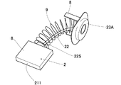
図5は本発明の実施例2を示し、上記実施例1と同一部分に同一符号を付し、その詳細な説明を省略して詳述すると、この例では、前記金属黒鉛ブラシ2と端子接続部23Aとの間に、前記スプリング9を一体に組み付けた小型のモータ用のものであり、該ブラシ2の露出する外面には先端面211を除いて四フッ化エチレン樹脂層8を形成している。
FIG. 5 shows a second embodiment of the present invention. The same reference numerals are given to the same parts as those of the first embodiment, and detailed description thereof is omitted. In this example, the
図6は本発明の実施例3を示し、上記各実施例と同一部分に同一符号を付し、その詳細な説明を省略して詳述すると、同図はフラットモータ11を示し、フラットモータ11は、ハウジング12内に設けた永久磁石13と僅かな間隔14をもって対設され、かつ、前記ハウジング12に回転自在に支持された扁平円盤状のアーマチュア15と、このアーマチュア15の盤面15Aに、先端平坦面16が弾性的に突設して給電する金属黒鉛ブラシ17とを備え、この金属黒鉛ブラシ17は、ハウジング12内に固着されたブラシロッカー19内に嵌挿され、常時バネたるコイルスプリング18によりアーマチュア15の盤面15Aに向って押圧されている。
FIG. 6 shows a third embodiment of the present invention. The same reference numerals are given to the same parts as those of the above-mentioned embodiments, and detailed description thereof will be omitted. Is a flat disk-shaped
そして、アーマチュア15,金属黒鉛ブラシ17,ブラシロッカー19の露出した外面に、前記被覆層である四フッ化エチレン樹脂層8を形成する。尚、この場合、アーマチュア15の盤面15Aは、前記ブラシ17の先端平坦面16が弾性的摺動する部分には四フッ化エチレン樹脂層8を形成せず、例えば、コーティングの際、前記摺動する部分をマスキングすることにより、四フッ化エチレン樹脂層8を設けない部分を形成する。
Then, the
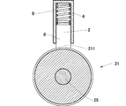
図7は本発明の実施例4を上記各実施形態と同一部分に同一符号を付し、その詳細な説明を省略して詳述すると、この例では、回転軸25にスリップリング31を設け、このスリップリング31に前記金属黒鉛ブラシ2が摺動して給電する例であり、通電部材であるスリップリング31は、前記金属黒鉛ブラシ2が摺動する部分を除いて露出する外面に四フッ化エチレン樹脂層8を形成しており、この例においても、金属黒鉛ブラシ2は、強度と共に、高い耐食性を備える。
FIG. 7 shows Example 4 of the present invention in which the same reference numerals are assigned to the same parts as those in the above embodiments, and detailed description thereof is omitted. In this example, a
なお、本発明は、前記実施形態に限定されるものではなく、種々の変形実施が可能である。例えば、金属黒鉛ブラシは、実施例のものに限らず種々の形状のものに適用可能である。 In addition, this invention is not limited to the said embodiment, A various deformation | transformation implementation is possible. For example, the metal graphite brush is applicable not only to the embodiment but also to various shapes.
1 モータ
2 金属黒鉛ブラシ
8 四フッ化エチレン樹脂層(被覆層)
17 金属黒鉛ブラシ
1
17 Metal graphite brush
Claims (3)
The metal graphite brush according to claim 1 or 2, further comprising a coating layer covering an outer surface, wherein the coating layer is a tetrafluoroethylene resin layer.
Priority Applications (1)
| Application Number | Priority Date | Filing Date | Title |
|---|---|---|---|
| JP2004107650A JP2005295699A (en) | 2004-03-31 | 2004-03-31 | Metal graphite brush |
Applications Claiming Priority (1)
| Application Number | Priority Date | Filing Date | Title |
|---|---|---|---|
| JP2004107650A JP2005295699A (en) | 2004-03-31 | 2004-03-31 | Metal graphite brush |
Publications (1)
| Publication Number | Publication Date |
|---|---|
| JP2005295699A true JP2005295699A (en) | 2005-10-20 |
Family
ID=35328022
Family Applications (1)
| Application Number | Title | Priority Date | Filing Date |
|---|---|---|---|
| JP2004107650A Pending JP2005295699A (en) | 2004-03-31 | 2004-03-31 | Metal graphite brush |
Country Status (1)
| Country | Link |
|---|---|
| JP (1) | JP2005295699A (en) |
Cited By (2)
| Publication number | Priority date | Publication date | Assignee | Title |
|---|---|---|---|---|
| CN106464094A (en) * | 2014-06-20 | 2017-02-22 | 株式会社村田制作所 | Sliding member, rotating machine, and sliding member manufacturing method |
| JP2023124185A (en) * | 2022-02-25 | 2023-09-06 | 株式会社東芝 | Brush for rotating electric machine, method for manufacturing brush for rotating electric machine, and rotating electric machine |
-
2004
- 2004-03-31 JP JP2004107650A patent/JP2005295699A/en active Pending
Cited By (5)
| Publication number | Priority date | Publication date | Assignee | Title |
|---|---|---|---|---|
| CN106464094A (en) * | 2014-06-20 | 2017-02-22 | 株式会社村田制作所 | Sliding member, rotating machine, and sliding member manufacturing method |
| JPWO2015194444A1 (en) * | 2014-06-20 | 2017-04-20 | 株式会社村田製作所 | Sliding member, rotating machine, manufacturing method of sliding member |
| CN106464094B (en) * | 2014-06-20 | 2019-10-25 | 株式会社村田制作所 | Sliding member, rotating machine, and manufacturing method of sliding member |
| US10505328B2 (en) | 2014-06-20 | 2019-12-10 | Murata Manufacturing Co., Ltd. | Sliding member, rotary device, and method for manufacturing sliding member |
| JP2023124185A (en) * | 2022-02-25 | 2023-09-06 | 株式会社東芝 | Brush for rotating electric machine, method for manufacturing brush for rotating electric machine, and rotating electric machine |
Similar Documents
| Publication | Publication Date | Title |
|---|---|---|
| KR100326850B1 (en) | Ceramic glow plug | |
| KR19980042533A (en) | Ceramic glow plugs | |
| JP4596404B2 (en) | Current-carrying member of direct current motor for fuel pump, manufacturing method thereof, and fuel pump | |
| JP2007277715A (en) | Plating material and electric / electronic component using the plating material | |
| EP1496573B1 (en) | Commutating device for small-sized motor and manufacturing method therefore | |
| US8878417B2 (en) | Commutator | |
| US9882331B2 (en) | Low cost gold wire brushes | |
| US7799430B2 (en) | Carbon commutator and process for producing the same | |
| US7642688B2 (en) | Metal-graphite brush | |
| JP2005295699A (en) | Metal graphite brush | |
| JP3770476B2 (en) | Metal graphite brush | |
| JP2003286922A (en) | Bearing for fuel pump, method for manufacturing the same, and fuel pump | |
| JP4253837B2 (en) | Motor parts with corrosion resistance | |
| JP5136840B2 (en) | Rotating electric machine | |
| JP5101235B2 (en) | Sn plating material for electronic parts and electronic parts | |
| JP4598238B2 (en) | Contact member and manufacturing method thereof | |
| US10505328B2 (en) | Sliding member, rotary device, and method for manufacturing sliding member | |
| JP2005240159A (en) | Cu-based sintered alloy bearing of motor-type fuel pump and motor-type fuel pump using the same | |
| JP5136841B2 (en) | Brush for rotating electrical machine and rotating electrical machine | |
| JP2006149144A (en) | Micromotor, sliding contact for micromotor and manufacturing method thereof | |
| KR100879794B1 (en) | Commutator for Vibration Motor, Vibration Motor and Plating Solution | |
| KR20080057026A (en) | Commutator for Vibration Motor, Vibration Motor and Plating Solution | |
| JP2004300485A (en) | Sliding parts and manufacturing method thereof | |
| JP2008099457A (en) | Dc motor | |
| JP2005057859A (en) | Small diameter motor |
Legal Events
| Date | Code | Title | Description |
|---|---|---|---|
| A711 | Notification of change in applicant |
Free format text: JAPANESE INTERMEDIATE CODE: A712 Effective date: 20060125 |
|
| RD02 | Notification of acceptance of power of attorney |
Free format text: JAPANESE INTERMEDIATE CODE: A7422 Effective date: 20060217 |
|
| A621 | Written request for application examination |
Free format text: JAPANESE INTERMEDIATE CODE: A621 Effective date: 20061214 |
|
| A131 | Notification of reasons for refusal |
Effective date: 20090525 Free format text: JAPANESE INTERMEDIATE CODE: A131 |
|
| A02 | Decision of refusal |
Free format text: JAPANESE INTERMEDIATE CODE: A02 Effective date: 20091023 |