JP2005295680A - Noncontact power supply apparatus and noncontact power supply system - Google Patents
Noncontact power supply apparatus and noncontact power supply system Download PDFInfo
- Publication number
- JP2005295680A JP2005295680A JP2004106833A JP2004106833A JP2005295680A JP 2005295680 A JP2005295680 A JP 2005295680A JP 2004106833 A JP2004106833 A JP 2004106833A JP 2004106833 A JP2004106833 A JP 2004106833A JP 2005295680 A JP2005295680 A JP 2005295680A
- Authority
- JP
- Japan
- Prior art keywords
- power
- voltage
- circuit
- power supply
- contact
- Prior art date
- Legal status (The legal status is an assumption and is not a legal conclusion. Google has not performed a legal analysis and makes no representation as to the accuracy of the status listed.)
- Pending
Links
- 230000001172 regenerating effect Effects 0.000 claims abstract description 151
- 238000007599 discharging Methods 0.000 abstract description 20
- 230000008929 regeneration Effects 0.000 description 31
- 238000011069 regeneration method Methods 0.000 description 31
- 238000009499 grossing Methods 0.000 description 20
- 239000003990 capacitor Substances 0.000 description 15
- 230000005540 biological transmission Effects 0.000 description 11
- 238000001514 detection method Methods 0.000 description 11
- 238000010586 diagram Methods 0.000 description 11
- 230000000694 effects Effects 0.000 description 7
- 238000006243 chemical reaction Methods 0.000 description 5
- 230000007423 decrease Effects 0.000 description 5
- 238000000034 method Methods 0.000 description 4
- 230000008569 process Effects 0.000 description 4
- 230000006870 function Effects 0.000 description 3
- 230000001133 acceleration Effects 0.000 description 2
- 230000008878 coupling Effects 0.000 description 2
- 238000010168 coupling process Methods 0.000 description 2
- 238000005859 coupling reaction Methods 0.000 description 2
- 230000004907 flux Effects 0.000 description 2
- 230000001939 inductive effect Effects 0.000 description 2
- 238000011084 recovery Methods 0.000 description 2
- 230000008054 signal transmission Effects 0.000 description 2
- 230000002411 adverse Effects 0.000 description 1
- 230000008859 change Effects 0.000 description 1
- 239000004020 conductor Substances 0.000 description 1
- 239000000428 dust Substances 0.000 description 1
- 230000005611 electricity Effects 0.000 description 1
- 230000020169 heat generation Effects 0.000 description 1
- 238000010248 power generation Methods 0.000 description 1
- 230000002040 relaxant effect Effects 0.000 description 1
- 238000005096 rolling process Methods 0.000 description 1
Images
Landscapes
- Electric Propulsion And Braking For Vehicles (AREA)
- Charge And Discharge Circuits For Batteries Or The Like (AREA)
- Current-Collector Devices For Electrically Propelled Vehicles (AREA)
Abstract
Description
本発明は、高周波電流が流れる給電線から物理的に非接触の状態で受電して負荷(例えばモータ)へ給電する非接触給電装置及び非接触給電システムに関する。 The present invention relates to a non-contact power supply apparatus and a non-contact power supply system that receive power from a power supply line through which a high-frequency current flows in a physically non-contact state and supply power to a load (for example, a motor).
非接触給電システムは、高周波電流が流れる給電線と、該給電線に対して非接触の状態で受電した電力をモータへ供給する受電回路を有する非接触給電装置とを備える。 The non-contact power supply system includes a power supply line through which a high-frequency current flows, and a non-contact power supply apparatus including a power receiving circuit that supplies power received in a non-contact state to the power supply line to a motor.
非接触給電システムは、例えば、搬送車又は昇降機等(以下、移動体という)を備える移動体システムに、駆動用の電力を供給する。この場合、非接触給電装置は移動体に設置されて、移動体が備えるモータへ給電する。このような非接触給電装置は、例えば、給電線に対して非接触の状態で誘導結合されたピックアップコイルを備え、該ピックアップコイルに誘起された電力をモータへ供給するよう構成してある(例えば、特許文献1参照)。 The non-contact power supply system supplies power for driving to a moving body system including, for example, a transport vehicle or an elevator (hereinafter referred to as a moving body). In this case, the non-contact power supply device is installed on the moving body and supplies power to the motor included in the moving body. Such a non-contact power supply device includes, for example, a pickup coil that is inductively coupled to the power supply line in a non-contact state, and is configured to supply electric power induced in the pickup coil to the motor (for example, , See Patent Document 1).
ところで、バッテリを備える電気自動車、又は給電線に対して物理的に接触した状態で給電される電車等においては、減速制動時に発生する回生電力を回収して、加速走行時にその電気自動車で利用したり、加速走行中の他の電車へ供給したりすることが一般に行なわれている(例えば、特許文献2,3参照)。
しかしながら、非接触給電を行なう装置又はシステム等においては、従来、回生電力の回収がなされておらず、そのような装置又はシステム等に抵抗器を備えて、該抵抗器に回生電力を供給し、供給された回生電力を熱として消費することが一般になされていた。 However, in a device or system that performs non-contact power feeding, conventionally, recovery of regenerative power has not been made, and a resistor is provided in such a device or system, and regenerative power is supplied to the resistor, Generally, the supplied regenerative power is consumed as heat.
また、特許文献4に開示された輸送設備は、モータを駆動するためのバッテリを電動移動体に備えており、そのバッテリに対して非接触で給電を行なうよう構成されているが、該バッテリは、回生電力を回収するよう構成されたものではない。 Further, the transportation facility disclosed in Patent Document 4 includes a battery for driving a motor in an electric vehicle, and is configured to supply power to the battery in a non-contact manner. It is not configured to collect regenerative power.
以上のようなことから、回生電力を有効利用できる非接触給電装置及び非接触給電システムが望まれている。 From the above, a non-contact power feeding apparatus and a non-contact power feeding system that can effectively use regenerative power are desired.
本発明は斯かる問題を解決するためになされたものであり、モータの回生電力を蓄電する蓄電回路を備えることにより、回生電力を蓄電回路に回収して有効利用できる非接触給電装置、及び該非接触給電装置を備える非接触給電システムを提供することを目的とする。 The present invention has been made to solve such a problem, and includes a power storage circuit that stores regenerative power of a motor so that the regenerative power can be recovered in the power storage circuit and effectively used, and An object of the present invention is to provide a non-contact power feeding system including a contact power feeding device.
本発明の他の目的は、モータの回生電力を外部の受電手段へ供給する供給手段を備えることにより、回生電力を外部で回収して有効利用できる非接触給電装置を提供することにある。 Another object of the present invention is to provide a non-contact power feeding device that is provided with a supply unit that supplies regenerative power of a motor to an external power receiving unit, so that the regenerative power can be recovered externally and used effectively.
本発明の更に他の目的は、受電手段と、該受電手段へモータの回生電力を供給する供給手段を有する非接触給電装置とを備えることにより、回生電力を回収して有効利用できる非接触給電システムを提供することにある。 Still another object of the present invention is to provide a non-contact power supply capable of recovering and effectively using regenerative power by including a power receiving means and a non-contact power supply device having a supply means for supplying regenerative power of a motor to the power receiving means. To provide a system.
第1発明に係る非接触給電装置は、交流電流が流れる給電線から非接触で受電してモータへ給電する受電回路を備える非接触給電装置において、モータの回生電力を蓄電する蓄電回路を備えることを特徴とする。 A contactless power supply device according to a first aspect of the present invention is a contactless power supply device including a power receiving circuit that receives power from a power supply line through which an alternating current flows in a contactless manner and supplies power to the motor, and includes a power storage circuit that stores regenerative power of the motor. It is characterized by.
第1発明にあっては、例えば、高周波電流が流れる給電線から非接触で受電する受電回路の出力部に、モータと、バッテリ又はコンデンサ等を用いてなる蓄電回路とを接続し、モータによって駆動される昇降機の下降時、又は搬送車の減速時等にモータが発生させる回生電力を蓄電回路に充電する。この場合、蓄電回路は回生電力を回収する。 In the first invention, for example, a motor and a power storage circuit using a battery or a capacitor are connected to an output portion of a power receiving circuit that receives power in a non-contact manner from a power feeding line through which a high-frequency current flows, and is driven by the motor The regenerative power generated by the motor when the elevator is lowered or when the transport vehicle is decelerated is charged in the storage circuit. In this case, the power storage circuit collects regenerative power.
回生電力を回収した蓄電回路は、昇降機の上昇時又は搬送車の加速時等に放電して、モータ及び/又はモータ以外の負荷へ給電することができる。このため、回生電力を、該非接触給電装置を備える昇降機内又は搬送車内で有効に利用することができる。 The power storage circuit that has recovered the regenerative power can be discharged when the elevator is raised or the vehicle is accelerated, and can be supplied to a motor and / or a load other than the motor. For this reason, regenerative electric power can be effectively utilized in an elevator provided with this non-contact electric power feeder, or a conveyance vehicle.
なお、蓄電回路が着脱可能に備えられている場合、回生電力を回収した蓄電回路は、装置から取り外され、他の負荷に接続されることによって、該負荷へ給電することができる。 In the case where the power storage circuit is detachably provided, the power storage circuit that has recovered the regenerative power can be powered from the device by being removed from the device and connected to another load.
以上のようにして、本発明の非接触給電装置は、従来、無駄に消費されていた回生電力を回収して、有効に利用することができる。 As described above, the non-contact power feeding device of the present invention can recover the regenerative power that has been conventionally wasted and can be used effectively.
第2発明に係る非接触給電装置は、前記蓄電回路への回生電力の供給を入断する第1スイッチ回路と、前記受電回路の電圧を検出する手段、検出した電圧と所定の第1電圧とを比較する手段、及び、比較結果の高/低に応じて、前記第1スイッチ回路の入/断を制御する手段を有する第1制御回路とを備えることを特徴とする。 A contactless power supply device according to a second aspect of the present invention includes a first switch circuit that cuts off the supply of regenerative power to the power storage circuit, means for detecting the voltage of the power receiving circuit, the detected voltage, and a predetermined first voltage. And a first control circuit having means for controlling on / off of the first switch circuit according to the comparison result high / low.
第2発明にあっては、第1スイッチ回路が入である場合は蓄電回路へ電流が流入し、断である場合は電流が遮断されるように構成する。また、第1電圧として、モータによる回生電力発生時の電圧を用いる。該電圧は、垂下特性を有する受電回路においては、受電回路の最大出力電圧(無負荷時の出力電圧)より高い。 In the second invention, when the first switch circuit is on, the current flows into the power storage circuit, and when it is off, the current is cut off. Moreover, the voltage at the time of the regeneration electric power generation by a motor is used as a 1st voltage. In the power receiving circuit having the drooping characteristic, the voltage is higher than the maximum output voltage (output voltage at no load) of the power receiving circuit.
第1制御回路は、受電回路の電圧を検出し、検出した電圧が第1電圧以上である場合は第1スイッチ回路を入にして蓄電回路へ電流を流入させる。即ち回生電力を蓄電回路へ供給して、蓄電回路を充電する。また、検出した電圧が第1電圧未満である場合は第1スイッチ回路を断にして蓄電回路へ電流を流入させない。即ち蓄電回路の充電を停止する。 The first control circuit detects the voltage of the power receiving circuit, and when the detected voltage is equal to or higher than the first voltage, the first control circuit is turned on to flow current into the power storage circuit. That is, regenerative power is supplied to the power storage circuit to charge the power storage circuit. In addition, when the detected voltage is less than the first voltage, the first switch circuit is disconnected and no current flows into the power storage circuit. That is, charging of the storage circuit is stopped.
以上のようにして、モータで発生した回生電力を蓄電回路が回収するため、回生電力を無駄に消費することが防止できる。また、回生電力の発生中にのみ蓄電回路を充電することによって、モータへ供給すべき電力を蓄電回路が回収してしまうことが防止できる。 As described above, since the power storage circuit recovers the regenerative power generated by the motor, it is possible to prevent the regenerative power from being consumed wastefully. Further, by charging the power storage circuit only during the generation of regenerative power, it is possible to prevent the power storage circuit from collecting the power to be supplied to the motor.
また、蓄電回路の充電中は、受電回路の電圧が第1電圧に略等しくなるため、第1電圧を、装置を構成する各機器及びモータが使用可能である電圧の上限以下の電圧としておく場合、回生電力発生時の過電圧によって各機器又はモータが停止したり破損したりすることが防止できる。 In addition, since the voltage of the power receiving circuit becomes substantially equal to the first voltage while the power storage circuit is being charged, the first voltage is set to a voltage equal to or lower than the upper limit of the voltage that can be used by each device and motor constituting the device. It is possible to prevent each device or motor from being stopped or damaged due to an overvoltage at the time of generating regenerative power.
第3発明に係る非接触給電装置は、前記蓄電回路からの放電を入断する第2スイッチ回路を備え、前記第1制御回路は、検出した電圧と前記第1電圧より低い第2電圧とを比較する手段、検出した電圧が前記第2電圧以下である場合、前記第2スイッチ回路を入にする手段、及び、検出した電圧が前記第1電圧以上である場合、前記第2スイッチ回路を断にする手段を更に有することを特徴とする。 A contactless power supply device according to a third aspect of the present invention includes a second switch circuit that turns on and off a discharge from the power storage circuit, and the first control circuit generates a detected voltage and a second voltage lower than the first voltage. Means for comparing, means for turning on the second switch circuit if the detected voltage is less than or equal to the second voltage, and disconnecting the second switch circuit if the detected voltage is greater than or equal to the first voltage. It further has a means to make it.
第3発明にあっては、第2スイッチ回路が入である場合は蓄電回路から電流が流出し、断である場合は電流が遮断されるように構成する。また、第2電圧として、モータが電力を消費している場合の電圧を用いる。該電圧は、垂下特性を有する受電回路においては、受電回路の最大出力電圧(無負荷時の出力電圧)より低い。 According to the third aspect of the invention, the current flows out from the power storage circuit when the second switch circuit is on, and the current is cut off when the second switch circuit is off. Further, the voltage when the motor is consuming electric power is used as the second voltage. In the power receiving circuit having a drooping characteristic, the voltage is lower than the maximum output voltage (output voltage at no load) of the power receiving circuit.
第1制御回路は、受電回路の電圧を検出し、検出した電圧が第2電圧以下である場合は第2スイッチ回路を入にして蓄電回路から電流を流出させる。即ち蓄電回路を放電させる。 The first control circuit detects the voltage of the power receiving circuit, and when the detected voltage is equal to or lower than the second voltage, the first control circuit is turned on to allow the current to flow out from the power storage circuit. That is, the storage circuit is discharged.
以上のようにして、蓄電回路が回収した回生電力をモータへ供給するため、回生電力を有効に利用することができる。 As described above, the regenerative power collected by the power storage circuit is supplied to the motor, so that the regenerative power can be used effectively.
また、モータが電力を消費している場合、即ちモータが回生電力を発生していない場合に、蓄電回路から、回収した回生電力を放電することによって、蓄電回路は再び充電可能になるため、回生電力を繰り返し充電/放電して、効率良く回収/利用することができる。 In addition, when the motor is consuming electric power, that is, when the motor is not generating regenerative power, by discharging the recovered regenerative power from the power storage circuit, the power storage circuit can be charged again. Electric power can be repeatedly charged / discharged for efficient recovery / utilization.
更に第1制御回路は、検出した電圧が第1電圧以上である場合に、第1スイッチ回路を入にして蓄電回路を充電し、第2スイッチ回路を断にして蓄電回路から電流を流出させない。即ち蓄電回路からの放電を停止する。 Further, when the detected voltage is equal to or higher than the first voltage, the first control circuit turns on the first switch circuit to charge the power storage circuit and disconnects the second switch circuit to prevent current from flowing out from the power storage circuit. That is, the discharge from the storage circuit is stopped.
このようにして蓄電回路の充電と放電とが同時に行なわれることを防止するため、回生電力を効率良く回収することができる。 In this way, regenerative power can be efficiently recovered in order to prevent the storage circuit from being charged and discharged simultaneously.
第4発明に係る非接触給電装置は、前記第1制御回路は、検出した電圧と前記第1電圧より低く前記第2電圧より高い第3電圧とを比較する手段、及び、前記第2スイッチ回路が入にされている場合に、検出した電圧が前記第3電圧以下であるとき、前記第2スイッチ回路を断にする手段を更に有することを特徴とする。 According to a fourth aspect of the present invention, in the non-contact power feeding device, the first control circuit compares the detected voltage with a third voltage lower than the first voltage and higher than the second voltage, and the second switch circuit. In the case where is turned on, when the detected voltage is equal to or lower than the third voltage, there is further provided means for disconnecting the second switch circuit.
第4発明にあっては、第3電圧として、例えば蓄電回路が放電する設定電圧より小さい電圧を用いる。受電回路の電圧が第3電圧以下になる状態とは、蓄電回路に充電されていた回生電力が減少して蓄電回路の出力電圧が第3電圧以下に低下し、モータが、受電回路から給電される電力も消費している状態である。 In the fourth aspect of the invention, for example, a voltage smaller than the set voltage at which the storage circuit is discharged is used as the third voltage. The state in which the voltage of the power receiving circuit is equal to or lower than the third voltage means that the regenerative power charged in the power storage circuit decreases, the output voltage of the power storage circuit decreases to the third voltage or lower, and the motor is fed from the power receiving circuit. It is in a state where power is consumed.
この状態のとき、第1制御回路が、第2スイッチ回路を断にして蓄電回路からの放電を停止するため、蓄電回路が回収した回生電力をモータが消費する場合にのみ蓄電回路から放電することができる。 In this state, the first control circuit cuts off the second switch circuit and stops the discharge from the power storage circuit, so that the regenerative power collected by the power storage circuit is discharged from the power storage circuit only when the motor consumes the regenerative power. Can do.
第5発明に係る非接触給電装置は、交流電流が流れる給電線から非接触で受電してモータへ給電する非接触給電装置において、モータの回生電力を外部の受電手段へ供給する供給手段を備えることを特徴とする。 A contactless power supply device according to a fifth aspect of the present invention is a contactless power supply device that receives power from a power supply line through which an alternating current flows in a contactless manner and supplies power to a motor, and includes a supply means that supplies regenerative power of the motor to external power receiving means. It is characterized by that.
第5発明にあっては、例えば、高周波電流が流れる給電線から非接触で受電する受電回路の出力部に、モータと、供給手段とを接続し、モータによって駆動される昇降機の下降時、又は搬送車の減速時等にモータが発生させる回生電力を、供給手段を介して外部の受電手段へ供給する。この場合、受電手段は回生電力を回収する。 In the fifth invention, for example, when a motor and a supply means are connected to an output portion of a power receiving circuit that receives power in a non-contact manner from a power feeding line through which a high-frequency current flows, or when the elevator driven by the motor is lowered, or Regenerative power generated by the motor when the transport vehicle is decelerated is supplied to the external power receiving means via the supply means. In this case, the power receiving means collects regenerative power.
回生電力を回収した受電手段は、回収した回生電力を、非接触給電装置外部の蓄電手段、商用電源、給電線への給電用の電源、又は他の負荷等へ給電することができるため、回生電力を装置外部で有効利用することができる。 The power receiving means that has recovered the regenerative power can supply the recovered regenerative power to the power storage means outside the non-contact power supply device, the commercial power supply, the power supply for supplying power to the power supply line, or other loads. Electric power can be effectively used outside the apparatus.
以上のようにして、本発明の非接触給電装置は、従来、無駄に消費されていた回生電力を回収して、有効に利用することができる。 As described above, the non-contact power feeding device of the present invention can recover the regenerative power that has been conventionally wasted and can be used effectively.
第6発明に係る非接触給電装置は、前記受電手段は電線であり、前記供給手段は、前記受電手段に誘導結合すべき供給部と、該供給部への回生電力の供給を入断する第3スイッチ回路とを備えることを特徴とする。 In the non-contact power feeding device according to a sixth aspect of the invention, the power receiving means is an electric wire, and the supply means is a first supply section to be inductively coupled to the power reception means, and the supply power to the supply section is switched on and off. And a three-switch circuit.
第6発明にあっては、第3スイッチ回路が入である場合は供給手段へ電流が流入し、断である場合は電流が遮断されるように構成する。第3スイッチ回路の入断は、例えば、回生電力が発生しているか否かを検出し、この検出結果に応じて切り替える。即ち、回生電力が発生している場合は第3スイッチ回路を入にし、発生していない場合は断にする。 In the sixth invention, when the third switch circuit is on, the current flows into the supply means, and when it is off, the current is cut off. The on / off of the third switch circuit is detected, for example, by detecting whether or not regenerative power is generated, and switching according to the detection result. That is, the third switch circuit is turned on when regenerative power is generated, and is turned off when it is not generated.
供給手段の供給部へは、回生電力を高周波電流に変換して流入させる。この場合、供給部と受電手段とは誘導結合して、供給部に流れる交流電流の周波数に等しい周波数を有する交流の電力が誘起される。受電手段は電線であるため、誘起された電力は、例えば受電手段に接続された蓄電手段又は電源等に回収される。 The regenerative power is converted into a high-frequency current and flows into the supply unit of the supply means. In this case, the supply unit and the power receiving means are inductively coupled to induce AC power having a frequency equal to the frequency of the AC current flowing through the supply unit. Since the power receiving means is an electric wire, the induced power is recovered by, for example, a power storage means or a power source connected to the power receiving means.
以上のようにして、モータが回生電力を発生させている場合に、発生した回生電力を、誘導起電力として外部の受電手段に回収させることができるため、回生電力を装置外部で有効に利用することができる。 As described above, when the motor generates regenerative power, the generated regenerative power can be collected as an induced electromotive force by an external power receiving means, so that the regenerative power is effectively used outside the apparatus. be able to.
第7発明に係る非接触給電装置は、交流電流が流れる給電線から非接触で受電してモータへ給電するための受電回路を備え、前記供給手段は、前記受電回路の電圧を検出する手段、及び、該手段が検出した電圧の高/低に応じて、前記第3スイッチ回路の入/断を制御する手段を有する第2制御回路を備えることを特徴とする。 A contactless power supply device according to a seventh aspect of the present invention includes a power receiving circuit for receiving power from a power supply line through which an alternating current flows in a contactless manner and supplying power to the motor, and the supply means detects a voltage of the power receiving circuit; And a second control circuit having means for controlling on / off of the third switch circuit according to the high / low voltage detected by the means.
第7発明にあっては、供給手段が、受電回路の出力電圧を検出し、検出した電圧と、所定の電圧とを比較する。この所定の電圧として、モータによる回生電力発生時の電圧(例えば、第2発明で用いた第1電圧)を用いる。検出した電圧が所定の電圧以上である場合、発生した回生電力を供給手段から受電手段に供給させるべく、制御手段が第3スイッチ回路を入にする。また、検出した電圧が所定の電圧未満である場合、回生電力以外の電力を供給手段から受電手段に回収させることを防止すべく、制御手段が第3スイッチ回路を断にする。 In the seventh invention, the supplying means detects the output voltage of the power receiving circuit, and compares the detected voltage with a predetermined voltage. As this predetermined voltage, a voltage when regenerative power is generated by the motor (for example, the first voltage used in the second invention) is used. When the detected voltage is equal to or higher than the predetermined voltage, the control means turns on the third switch circuit to supply the generated regenerative power from the supply means to the power receiving means. Further, when the detected voltage is less than the predetermined voltage, the control means disconnects the third switch circuit in order to prevent the power receiving means from collecting power other than regenerative power from the supply means.
以上のようにして、回生電力の発生中にのみ供給手段へ電力を供給することによって、モータへ供給すべき電力を供給手段が回収してしまうことを防止でき、回生電力を適切に回収することができる。 As described above, by supplying power to the supply means only during the generation of regenerative power, it is possible to prevent the supply means from collecting the power to be supplied to the motor, and to properly recover the regenerative power. Can do.
また、供給手段から受電手段への電力供給中は、モータの電圧が所定の電圧に略等しくなるため、所定の電圧を、装置を構成する各機器及びモータが使用可能である電圧の上限以下の電圧としておく場合、回生電力発生時の過電圧によって各機器又はモータが停止したり破損したりすることを防止できる。 Further, during the power supply from the supply means to the power reception means, the voltage of the motor becomes substantially equal to the predetermined voltage. When the voltage is set, it is possible to prevent each device or the motor from being stopped or damaged due to an overvoltage when the regenerative power is generated.
第8発明に係る非接触給電システムは、交流電流が流れる給電線と第1発明乃至第4発明の何れか一つに係る非接触給電装置とを備えることを特徴とする。 A contactless power supply system according to an eighth aspect of the invention includes a power supply line through which an alternating current flows and the contactless power supply device according to any one of the first to fourth aspects of the invention.
第8発明にあっては、システムに備えられた非接触給電装置が、第1発明乃至第4発明の何れか一つに係る非接触給電装置であるため、該非接触給電装置の効果を得て、従来、無駄に消費されていた回生電力を、有効に利用することができる。 In the eighth invention, since the non-contact power feeding device provided in the system is the non-contact power feeding device according to any one of the first to fourth inventions, the effect of the non-contact power feeding device is obtained. Thus, it is possible to effectively use the regenerative power that has conventionally been wasted.
第9発明に係る非接触給電システムは、商用電源から受電して交流電流を出力する電源装置と、該電源装置から出力された交流電流が流れる給電線と、該給電線から非接触で受電してモータへ給電する非接触給電装置とを備える非接触給電システムにおいて、前記非接触給電装置は第5発明乃至第7発明の何れか一つに係る非接触給電装置であり、該非接触給電装置が供給する回生電力を受電する受電手段と、該受電手段が受電した回生電力を、前記商用電源又は前記電源装置へ供給する手段とを備えることを特徴とする。 A contactless power supply system according to a ninth aspect of the present invention is a power supply device that receives power from a commercial power supply and outputs an alternating current, a power supply line through which the alternating current output from the power supply device flows, and a power supply that receives contactlessly from the power supply line. A non-contact power feeding system including a non-contact power feeding device that feeds power to the motor, wherein the non-contact power feeding device is a non-contact power feeding device according to any one of the fifth to seventh inventions, And a power receiving means for receiving the regenerative power to be supplied, and a means for supplying the regenerative power received by the power receiving means to the commercial power supply or the power supply apparatus.
第9発明にあっては、非接触給電装置が備えている供給手段から供給された回生電力を、受電手段を介して、システム内部の電源装置、又は商用電源へ供給することができるため、従来、無駄に消費されていた回生電力を、システム内部又は外部にて、有効に利用することができる。 In the ninth invention, since the regenerative power supplied from the supply means provided in the non-contact power supply device can be supplied to the power supply device inside the system or the commercial power supply via the power receiving means, The regenerative power that has been wasted can be used effectively inside or outside the system.
第10発明に係る非接触給電システムは、商用電源から受電して交流電流を出力する電源装置と、該電源装置から出力された交流電流が流れる給電線と、該給電線から非接触で受電してモータへ給電する非接触給電装置とを備える非接触給電システムにおいて、前記非接触給電装置は第5発明乃至第7発明の何れか一つに係る非接触給電装置であり、該非接触給電装置が供給する回生電力を受電する受電手段は前記給電線であり、該給電線が受電した回生電力を、前記商用電源又は前記電源装置へ供給する手段を備えることを特徴とする。 A contactless power supply system according to a tenth aspect of the present invention is a power supply device that receives power from a commercial power supply and outputs an alternating current, a power supply line through which the alternating current output from the power supply device flows, and a power supply that receives contactlessly from the power supply line. A non-contact power feeding system including a non-contact power feeding device that feeds power to the motor, wherein the non-contact power feeding device is a non-contact power feeding device according to any one of the fifth to seventh inventions, The power receiving means for receiving the regenerative power to be supplied is the power supply line, and includes means for supplying the regenerative power received by the power supply line to the commercial power supply or the power supply apparatus.
第10発明にあっては、非接触給電装置が備えている供給手段から供給された回生電力を、受電手段を介して、システム内部の電源装置、又は商用電源へ供給することができるため、従来、無駄に消費されていた回生電力を、システム内部又は外部にて、有効に利用することができる。 In the tenth invention, the regenerative power supplied from the supply means provided in the non-contact power supply device can be supplied to the power supply device in the system or the commercial power supply via the power reception means. The regenerative power that has been wasted can be used effectively inside or outside the system.
また、受電手段と給電線とが一体であるため、給電線とは別体の受電手段を設ける必要がなく、システムを小型化することができる。 Further, since the power receiving means and the power supply line are integrated, it is not necessary to provide a power receiving means separate from the power supply line, and the system can be miniaturized.
本発明の非接触給電装置及び非接触給電システムによれば、モータが回生電力を発生させている場合に、発生した回生電力を蓄電回路に充電し、例えば、モータが回生電力を発生させていないときに、受電回路からモータへ給電するよりも優先的に、充電してある電力を蓄電回路から放電してモータへ供給することにより、従来、無駄に消費されていた回生電力を有効に利用することができる。このため、システムの消費電力を低減して、省エネルギの効果を得ることができる。 According to the non-contact power supply device and the non-contact power supply system of the present invention, when the motor generates regenerative power, the generated regenerative power is charged in the storage circuit, for example, the motor does not generate regenerative power. In some cases, regenerative power that has been wasted in the past can be used effectively by discharging the charged power from the power storage circuit and supplying it to the motor in preference to supplying power from the power receiving circuit to the motor. be able to. For this reason, the power consumption of a system can be reduced and the effect of energy saving can be acquired.
また、モータの消費電力が大きい場合に、受電回路からモータへ給電すると共に、充電してある電力を蓄電回路から放電してモータへ供給するときは、受電回路の受電容量を、モータの消費電力に応じて大きく設ける必要がない。このため、ピックアップコア及び共振回路等の各機器を小型化することができる。 In addition, when the power consumption of the motor is large, power is supplied from the power receiving circuit to the motor, and when the charged power is discharged from the power storage circuit and supplied to the motor, the power receiving capacity of the power receiving circuit is set to the power consumption of the motor. It is not necessary to provide a large size depending on the case. For this reason, each apparatus, such as a pickup core and a resonance circuit, can be reduced in size.
また、蓄電回路を備えることによって、従来の非接触給電回路に備えられていた回生電力消費用の抵抗器を備える必要がなくなり、また、一般に、このような抵抗器よりも蓄電回路の方が小さく構成できるため、装置を小型化することができる。 In addition, the provision of the storage circuit eliminates the need for a regenerative power consumption resistor provided in a conventional non-contact power supply circuit, and the storage circuit is generally smaller than such a resistor. Since it can be configured, the apparatus can be miniaturized.
更に、非接触給電装置は、モータが回生電力を発生させているか否か、又は、モータが電力を消費しているか否かを、受電回路の電圧の高低を用いて検知し、これに応じて蓄電回路を充電したり蓄電回路から放電したりする。この場合、回生電力の発生中は蓄電回路を充電して放電を停止し、電力の消費中は蓄電回路から放電して充電を停止する。このため、回生電力の電圧による過電圧でモータが停止したり装置を構成する機器が破損したりする前に、装置の電圧を減少させることができる。また、蓄電回路の充放電を効率良く行なうことができる。 Furthermore, the non-contact power feeding device detects whether the motor is generating regenerative power or whether the motor is consuming power using the voltage level of the power receiving circuit, and according to this, The power storage circuit is charged or discharged from the power storage circuit. In this case, while the regenerative power is generated, the power storage circuit is charged to stop discharging, and while the power is consumed, the power storage circuit is discharged to stop charging. For this reason, the voltage of the apparatus can be reduced before the motor stops due to an overvoltage due to the voltage of the regenerative power or the equipment constituting the apparatus is damaged. In addition, the storage circuit can be charged and discharged efficiently.
また、本発明の非接触給電装置及び非接触給電システムによれば、モータが回生電力を発生させている場合に、発生した回生電力を外部の受電手段に供給することにより、従来、無駄に消費されていた回生電力を有効に利用することができるため、消費電力を低減して、省エネルギの効果を得ることができる。 Further, according to the non-contact power supply apparatus and the non-contact power supply system of the present invention, when the motor generates regenerative power, the generated regenerative power is supplied to an external power receiving means, which is conventionally consumed wastefully. Since the regenerated electric power that has been used can be used effectively, the power consumption can be reduced and the energy saving effect can be obtained.
また、回生電力を、非接触で受電手段に回収させるため、回生電力の回収に際し、受電手段と供給手段との移動しながらの接触によるゴミの発生を防止することができ、また、受電手段と供給手段との接触部となる導体を露出させる必要がなく、更に、非接触給電装置の移動中に、受電手段と供給手段とを接触させるために非接触給電装置を停止させる必要がない等の効果を得ることができる。 In addition, since the regenerative power is collected in a non-contact manner by the power receiving means, it is possible to prevent the generation of dust due to the contact between the power receiving means and the supply means when the regenerative power is collected. There is no need to expose the conductor that is in contact with the supply means, and there is no need to stop the non-contact power supply device to bring the power receiving means and the supply means into contact while the non-contact power supply device is moving. An effect can be obtained.
更に、非接触給電装置内部ではなく、受電手段を介して装置外部で回収し、更に、商用電源又は電源装置等に回収するため、回収した回生電力を再び非接触給電装置へ供給するのみならず、システム内部の他の非接触給電装置、あるいはシステム外部の他の負荷へ供給することが容易である等、本発明は優れた効果を奏する。 Furthermore, not only inside the non-contact power supply device but also outside the device via the power receiving means, and further to the commercial power supply or power supply device etc., not only the recovered regenerative power is supplied to the non-contact power supply device again. The present invention has an excellent effect that it can be easily supplied to another non-contact power feeding device inside the system or another load outside the system.
以下、本発明を、その実施の形態を示す図面に基づいて詳述する。 Hereinafter, the present invention will be described in detail with reference to the drawings illustrating embodiments thereof.
(実施の形態 1.)
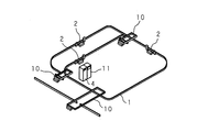
図1は、本発明の実施の形態1に係る非接触給電システムを用いた移動体システムの構成を示す斜視図である。
(
FIG. 1 is a perspective view showing a configuration of a mobile system using the non-contact power feeding system according to
図中1は、モノレール方式の移動体システムを構成するレールである。レール1は、工場又は倉庫等の天井に敷設されており、レール1に、システムコントローラ11によって駆動制御される複数の移動体2,2,…が夫々懸架されている。また、レール1は、図示しない複数のステーションを結んで、多重のループ状に設けられており、このため、交差部を有する。
In the figure,
交差部には、スイッチレール方式の分岐・合流部10,10,…が設けられており、分岐・合流部10,10,…は、移動体2,2,…の目的地に応じて、レール1を切り替えるよう構成してある。
.. Are provided at the intersections, and switch rail type branching / merging
各移動体2は、非接触給電システムを介して駆動用の電力を得る。非接触給電システムは、AC200V、60Hzの商用電源から受電して、10KHzの定電流(振幅一定又は実効電流一定の交流電流)を出力する高周波電源装置4(電源装置)を備える。
Each moving
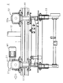
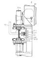
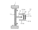
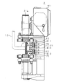
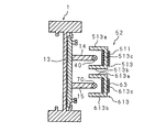
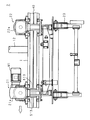
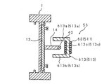
図2及び図3は、移動体システムに備えられた移動体2の構成を示す側面図及び正面図であり、図4は、非接触給電システムが備える給電線40及びピックアップコイル511を示す断面図である。
2 and 3 are a side view and a front view showing a configuration of the moving
レール1はI字型の断面形状を有し、その一側面には、支持腕12,12,…が、レール1の長手方向に適宜の間隔で設けられている。支持腕12,12,…によって、レール1は天井から略水平に吊り下げられている。
The
レール1の他側面には、取付板13がネジ留めされており、取付板13の上下方向中央部に、多数の棒状部材を用いてなる支持部材14,14,…が、略水平に並んで設けられている。
A mounting
給電線40は、支持部材14,14,…の先端部に固定されることによって、レール1に沿って敷設されている。また、給電線40は、高周波電源装置4に接続されており(図5参照)、高周波電源装置4によって10KHzの交流定電流を供給されている。
The
各移動体2は、正面視がコの字状である前後一対の車体枠21,22を備え、車体枠21,22の上部に、前輪21a及び後輪22aを夫々回動可能に備える。前輪21a及び後輪22aをレール1に転接させることによって、移動体2は、レール1に懸架される。また、車体枠21は、前輪21a近傍に、前輪21aに連繋する走行用のモータM1を固定してある。また、移動体2は、被搬送物を着脱可能に取り付けることができるキャリア23を備え、キャリア23は、車体枠21,22夫々の下部にわたして設けられ、昇降用のモータM2(図5参照)によって昇降自在に駆動されるよう車体枠21,22によってレール1の下側に吊り下げられている。移動体2は、システムコントローラ11に制御されて、キャリア23にて一のステーション上の被搬送物を持ち上げ、白抜矢符方向へ走行し、その被搬送物を他のステーション上へ下ろす。
Each moving
移動体2は、ピックアップコイル511及びピックアップコア513を備える非接触給電装置51を搭載してあり、非接触給電装置51にモータM1,M2,…を接続して、非接触給電装置51を介し、給電線40から駆動用の電力を得るよう構成されている。
The moving
ピックアップコア513は、ピックアップコイル511を巻装してあり、車体枠21のレール1側に固定されている。ピックアップコア513は、断面形状がコの字状に形成された磁性体であり、ピックアップコイル511を巻回してある柱部513cと、柱部513cの両端に夫々設けられた突起部513a,513bとを有する。
The
レール1に移動体2を載架する場合は、ピックアップコア513が、給電線40と所定の間隔を隔てて対面し、給電線40が突起部513a,513bの間に位置するよう配置する。
When the moving
高周波電源装置4によって給電線40に高周波交流電流が通電された場合、給電線40の周囲に、時間的に変化する磁束が形成される。非接触給電装置51は、その磁束がピックアップコイル511に鎖交することによってピックアップコイル511に発生した誘導起電力を受電し、モータM1,M2,…へ供給するよう構成してある。
When a high-frequency alternating current is applied to the
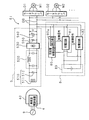
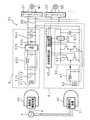
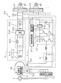
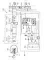
図5は、非接触給電システムが備える非接触給電装置51の構成を示す電気回路図である。
FIG. 5 is an electric circuit diagram showing a configuration of a non-contact
図中9は商用電源であり、商用電源9に接続された高周波電源装置4は、商用電源9の出力を整流し、平滑化して直流とし、該直流をインバータ(DC−AC変換器)に入力して高周波交流電流に変換して、変換した高周波電流を給電線40へ定電流として出力する。
In the figure, 9 is a commercial power supply, and the high frequency power supply device 4 connected to the commercial power supply 9 rectifies and smoothes the output of the commercial power supply 9 to obtain a direct current, and the direct current is input to an inverter (DC-AC converter). Then, it is converted into a high-frequency alternating current, and the converted high-frequency current is output to the
各移動体2に搭載してある非接触給電装置51は、受電回路5と蓄電部8とを備える。また、受電回路5の出力部に、DCバスDBを介してモータドライバD1,D2,…が接続してあり、モータドライバD1,D2,…は、負荷としてのモータM1,M2,…を駆動する。モータM1,M2,…は交流モータであり、モータドライバD1,D2,…を介して、受電回路5の出力部に接続してある。
The non-contact
受電回路5は共振回路部510を備え、共振回路部510は、ピックアップコイル511と、ピックアップコイル511に並列に接続された共振コンデンサ512とを備える。共振回路部510は、給電線40に誘導結合すべく、給電線40に対し離隔配置されているピックアップコイル511のインダクタンスと、共振コンデンサ512のキャパシタンスとが、給電線40を流れる高周波交流電流の周波数と共振状態になるよう構成されている。即ち、共振回路部510は、ピックアップコイル511に誘起された電力を受けて、高周波交流の定電流源として機能する。
The
受電回路5は、共振回路部510の他に、共振回路部510の出力である交流定電流を定電圧(振幅一定又は実効電圧一定の交流電圧)に変換するイミタンス変換回路520と、イミタンス変換回路520の出力である交流定電圧を全波整流するダイオードブリッジを用いた整流回路530と、平滑コンデンサを用いてなり、整流回路530が出力した全波整流波形を平滑化する平滑回路540とを備える。また、受電回路5は、整流回路530と平滑回路540との間に、高周波電源装置4及びモータM1,M2,…が停止している場合にコンデンサ540に蓄電されている電荷を放電するための抵抗器550を備える。
In addition to the
なお、整流回路530を、全波整流するダイオードブリッジの代わりに半波整流するダイオードを用いて構成しても良い。また、抵抗器550は、平滑回路540と受電回路5の出力部との間に備えられていても良い。
Note that the
受電回路5は、共振回路部510の出力(定電流)を、イミタンス変換回路520で定電圧に変換し、整流回路530で全波整流し、平滑回路540で平滑することによって、直流電流をモータドライバD1,D2,…へ供給する。
The
モータドライバD1,D2,…はインバータ機能を有するよう構成してあり、供給された直流電流を交流電流に変換して、モータM1,M2,…へ供給する。モータM1,M2,…は、交流電流を受けて回転する。また、モータM1,M2,…は、回生電力を発生する場合、発電機として機能して交流電流を出力する。モータM1,M2,…から交流電流が出力された場合、モータドライバD1,D2,…は、その交流電流を直流電流に変換して出力する。 The motor drivers D1, D2,... Are configured to have an inverter function, convert the supplied direct current into alternating current, and supply the alternating current to the motors M1, M2,. The motors M1, M2,... Rotate by receiving an alternating current. When generating regenerative power, the motors M1, M2,... Function as a generator and output an alternating current. When alternating current is output from the motors M1, M2,..., The motor drivers D1, D2,... Convert the alternating current into direct current and output it.
受電回路5は垂下特性を有するため、その出力電圧は、無負荷時(モータM1,M2,…が停止しているとき)の電圧Vs が最大電圧であり、前記出力電圧は、モータM1,M2,…が駆動を開始することによって低下する。このため、回生電力が発生していない場合、受電回路5の出力部の電圧VはV≦Vsである。一方、回生電力が発生した場合、受電回路5の出力部の電圧VはV>Vs となる。このため、モータドライバD1,D2,…が出力した直流電流は、非接触給電装置51の蓄電部8へ流入する。
Since the
蓄電部8は、充放電制御回路80と、バッテリを用いてなる蓄電回路83とを備え、蓄電回路83は、充電回路81及び放電回路82を夫々介して、DCバスDBに接続されている。また、充放電制御回路80も、DCバスDBに接続されている。
The power storage unit 8 includes a charge /
充放電制御回路80(第1制御回路)は、受電回路5の出力部の電圧Vを検出する検出部80aを備え、検出した電圧Vが第1電圧V1 以上である場合、充電回路81へ制御信号を伝送し、かつ、放電回路82への制御信号の伝送を停止する。また、検出した電圧Vが第1電圧V1未満である場合、充電回路81への制御信号の伝送を停止する。また、検出した電圧Vが第2電圧V2 以下である場合、放電回路82への制御信号の伝送を行ない、放電回路82への制御信号の伝送中に検出した電圧Vが第3電圧V3以下であるとき、放電回路82への制御信号の伝送を停止する。
Charge and discharge control circuit 80 (first control circuit), if provided with a detecting portion 80a for detecting the voltage V at the output of the receiving
第1電圧V1 、第2電圧V2 、及び第3電圧V3 は、予め定められて充放電制御回路80に設定される(後述)。 The first voltage V 1 , the second voltage V 2 , and the third voltage V 3 are predetermined and set in the charge / discharge control circuit 80 (described later).
充電回路81(第1スイッチ回路)は、制御信号が伝送された場合に、受電回路5及びモータドライバD1,D2,…側から流入する電流を通電し(即ち充電回路81が入になり)、制御信号が伝送されない場合に、電流を遮断する(即ち充電回路81が断になる)よう構成してある。
When the control signal is transmitted, the charging circuit 81 (first switch circuit) energizes the current flowing from the
放電回路82(第2スイッチ回路)は、制御信号が伝送された場合に、蓄電回路83側から流入する電流を通電して(即ち放電回路82が入になり)、受電回路5の最大出力電圧(無負荷時の電圧)である電圧Vs より高い電圧Vd の定電圧として出力し、制御信号が伝送されない場合に、電流を遮断する(即ち放電回路82が断になる)よう構成してある。
When the control signal is transmitted, the discharge circuit 82 (second switch circuit) energizes the current flowing from the
充放電制御回路80に設定される第1電圧V1 としては、電圧Vs 及び電圧Vdより大きく、非接触給電装置51の各機器、モータドライバD1,D2,…、及びモータM1,M2,…が使用可能である電圧の上限以下の電圧を用いる。第2電圧V2としては、受電回路5の最大出力電圧Vs より僅かに低い電圧を用いる。第3電圧V3 としては、放電回路82の出力電圧Vdより低く第2電圧V2 より高い電圧を用いる。
The first voltage V 1 set in the charge /
なお、蓄電回路83は、バッテリではなく、スーパーコンデンサ(電気二重層コンデンサ)、又は大容量のコンデンサ等を用いて構成しても良い。また、放電回路82の出力電圧Vd は、受電回路5の最大出力電圧Vs 以下の電圧であっても良い。更にまた、蓄電回路83の放電が進むとバッテリ電圧が低下し、放電回路82の出力電圧Vdが低下するため、第3電圧V3 として、第2電圧V2 より低い電圧を用いても良い。
Note that the
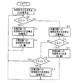
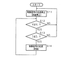
図6は、非接触給電装置51の蓄電回路83を充放電させる充放電制御回路80の動作を示すフローチャートである。
FIG. 6 is a flowchart showing the operation of the charge /
充放電制御回路80は、まず、充電回路81及び放電回路82への制御信号の伝送を停止する(S1)。即ち、移動体2の駆動開始前は、制御信号を伝送しない。このため、蓄電回路83の充放電は停止している。
The charge /
移動体2の駆動開始後、充放電制御回路80は、検出した電圧Vが、第1電圧V1 以上であるか否かを判定する(S2)。V≧V1 である場合(S2でYES)、充放電制御回路80は、放電回路82への制御信号の伝送を停止し(S3)、かつ、充電回路81へ制御信号を伝送する(S4)。即ち、S3にて蓄電回路83の放電が停止し、S4にて蓄電回路83が充電される。
After the driving of the moving
次いで、充放電制御回路80は、充電回路81へ制御信号を伝送しつつ、また、放電回路82へ制御信号を伝送しないまま、再びS2の動作を行なう。
Next, the charge /
充放電制御回路80は、S2にて、検出した電圧Vが第1電圧V1 以上であるか否かを判定し、V<V1 である場合(S2でNO)、充電回路81への制御信号の伝送を停止する(S5)。即ち、蓄電回路83の充電が停止する。
Charge and
次いで、充放電制御回路80は、検出した電圧Vが、第2電圧V2 以下であるか否かを判定する(S6)。V≦V2 である場合(S6でYES)、充放電制御回路80は、放電回路82へ制御信号を伝送する(S7)。即ち、蓄電回路83が放電する。
Next, the charge /
次いで、充放電制御回路80は、放電回路82へ制御信号を伝送しつつ、また、充電回路81へ制御信号を伝送しないまま、再びS2の動作を行なう。
Next, the charge /
充放電制御回路80は、S6にて、検出した電圧Vが第2電圧V2 以下であるか否かを判定し、V>V2 である場合(S6でNO)、検出した電圧Vが第3電圧V3以下であるか否かを判定する(S8)。V>V3 である場合(S8でNO)、充放電制御回路80は、放電回路82へ制御信号を伝送中であるときは、その伝送を継続しつつ、また、充電回路81へ制御信号を伝送しないまま、再びS2の動作を行ない、放電回路82へ制御信号を伝送中でないときは、充電回路81及び放電回路82へ制御信号を伝送しないまま、再びS2の動作を行なう。
Charge and
充放電制御回路80は、S8にて、検出した電圧Vが第3電圧V3 以下であるか否かを判定し、V≦V3 である場合(S8でYES)、放電回路82への制御信号の伝送を停止する(S9)。即ち、蓄電回路83の放電が停止する。
Charge and
次いで、充放電制御回路80は、充電回路81及び放電回路82へ制御信号を伝送しないまま、再びS2の動作を行なう。
Next, the charge /
以上のようにして、充放電制御回路80は、検出部80aにて受電回路5の電圧Vを検出し、S2にて、検出した電圧Vと第1電圧V1 とを比較し、比較結果の高低に応じて、S4,S5にて、充電回路81の入/断を制御する。
As described above, the charge and
また、充放電制御回路80は、検出部80aにて受電回路5の電圧Vを検出し、S6にて、検出した電圧Vと第2電圧V2 とを比較し、電圧Vが第2電圧V2 以下である場合、S7にて、放電回路82を入にし、電圧Vが第1電圧V1以上である場合、S3にて、放電回路82を断にする。
Further, the charge and
更に、充放電制御回路80は、検出部80aにて受電回路5の電圧Vを検出し、S7にて放電回路82を入にし、次いで、S8にて、検出した電圧Vと第3電圧V3 とを比較し、電圧Vが第3電圧V3 以下である場合、S9にて、放電回路82を断にする。
Further, the charge /
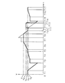
図7は、非接触給電装置51の受電回路5の電圧を示す特性図である。図中の縦軸は、充放電制御回路80が検出する受電回路5の出力部の電圧Vを示し、横軸は、経過時間tを示す。以下では、移動体2が、モータM1を停止させ、モータM2によってキャリア23を昇降させている場合を例示する。この場合、蓄電回路83は、モータM2の駆動開始前は、全く充電されていないものとする。
FIG. 7 is a characteristic diagram showing the voltage of the
移動体2がキャリア23を昇降させていない場合(図中T1)、モータM2は停止しており、電圧V=Vs (無負荷時の電圧、即ち受電回路5の最大電圧)であるが、キャリア23の上昇を開始させ、モータM2を加速駆動させている場合(T2)、電圧V<Vsである。この場合、電圧V≦V2 となったときに放電回路82が入にされるが、蓄電回路83に充電されていないため、放電は起こらない。次いで、モータM2が一定速度で駆動され(T3)、更に減速駆動され(T4)、停止する(T5)。
When the moving
次いで、移動体2が、キャリア23を下降させている場合(T6)、モータM2が回生電力を発生し、電圧V≧Vs となる。このとき、モータM2が発生させた回生電力は、受電回路5の平滑回路540に充電される。次いで、電圧V≧V1となった場合、充電回路81が入にされ、蓄電回路83が充電される。この後、蓄電回路83の充電中は、キャリア23を一定速度で下降させている場合であっても(T7)、減速しながら下降させている場合であっても(T8)、V<V1にならない限りは、V≒V1 で略一定になる。移動体2が、キャリア23を減速しながら下降させ続け、電圧V<V1 となった場合(T9)、充電回路81が断にされ、蓄電回路83の充電が停止する。このとき、モータM2が発生させた回生電力は、受電回路5の平滑回路540に充電される。
Then, the moving
次いで、モータM2が停止し、電圧V=Vs となる(T10)。 Next, the motor M2 is stopped, and the voltage V = V s (T10).
移動体2が、キャリア23の上昇を再び開始させ、モータM2を加速駆動させている場合(T11〜T14)、電圧V<Vs となり(T11)、電圧V≦V2 となったときに、放電回路82が入にされ、蓄電回路83が放電される(T12)。この場合、蓄電回路83の放電中は、電圧V≒Vdで略一定となり、蓄電回路83に充電されていた電力が減少した場合に電圧V<Vd となり(T13)、電圧V≦V3 となったときに、放電回路82が断にされ、蓄電回路83の放電が停止して、電圧V<Vsとなる(T14)。
When the moving
次いで、モータM2が一定速度で駆動され(T15)、更に減速駆動され(T16)、停止して、電圧V=Vs となる(T17)。 Next, the motor M2 is driven at a constant speed (T15), further decelerated (T16), stopped, and the voltage V = V s (T17).
以上のような非接触給電装置51は、蓄電回路83に対して回生電力を繰り返し充放電することによって、回生電力を回収し、移動体2内で有効に利用することができる。また、回生電力の発生中にのみ蓄電回路83を充電することによって、モータM1,M2,…へ供給すべき電力を蓄電回路83が回収してしまうことを防止できる。更に、回生電力を蓄電回路83へ供給することによって受電回路5の出力部の電圧Vを第1電圧V1 以下に保ち、受電回路5及びモータM1,M2,…等が過電圧によって停止したり破損したりすることを防止できる。
The non-contact
また、非接触給電装置51は、受電回路5を制御することなく、回生電力を回収/有効利用することができる。
Further, the non-contact
なお、受電回路5の出力部の電圧Vを直接的に検出するだけでなく、出力部の電圧Vに対応する電圧又は電流を検出することによって間接的に検出する構成であっても良い。
In addition, the configuration may be such that not only the voltage V of the output unit of the
また、蓄電回路83の電圧又は電流も検出し、該電圧又は電流の大小に応じて充放電を開始/停止させるよう構成しても良い。この場合、蓄電回路の過充電及び過放電を防止することができる。
Alternatively, the voltage or current of the
また、受電回路5の出力部の電圧Vが第1電圧V1 以上である場合にのみ蓄電回路83の放電を停止するよう構成しても良い。
Alternatively, the discharge of the
また、受電回路5の代わりに、安定化された(垂下特性を有しない)受電回路を用いて非接触給電装置を構成しても良い。この場合、受電回路の電圧Vの大小ではなく、受電回路の電流の向きに応じて充放電を制御する。
Further, instead of the
更に、充放電制御回路80は、第1電圧V1 及び第2電圧V2 等を発生させる基準電圧発生回路、並びに、該基準電圧発生回路が発生させた電圧と受電回路5の出力部の電圧Vとの大小を比較し、比較結果に応じて所定の信号を出力する比較回路等を用いてアナログ回路として構成しても良い。即ち、基準電圧発生回路及び比較回路等を用いて検出部80aを構成し、この検出部80aで受電回路の電圧Vを検出し、検出した電圧Vと所定の電圧とを比較し、比較結果の高/低に応じて、各スイッチ回路の入/断を制御するよう構成する。
Further, the charge /
又は、充放電制御回路80は、受電回路5の出力部の電圧Vを検出する電圧センサ、第1電圧V1 及び第2電圧V2 等を記憶するメモリ、並びに、電圧センサである検出部80aの検出結果とメモリに記憶された電圧とを比較し、比較結果に応じて所定の信号を出力するCPU等を用いてデジタル回路として構成しても良い。即ち、検出部80a、メモリ、及びCPU等を用いて、受電回路の電圧Vを検出し、検出した電圧Vと所定の電圧とを比較し、比較結果の高/低に応じて、各スイッチ回路の入/断を制御するよう構成する。
Or, the charge and
(実施の形態 2.)
以下では、移動体システム(図1参照)に駆動用の電力を供給し、また、回生電力を回収して商用電源へ供給する非接触給電システム、及び該非接触給電システムを構成し、モータが発生させた回生電力を受電手段へに供給する非接触給電装置52を例示する。また、本実施の形態では、非接触給電装置52から供給された回生電力を受電する受電手段として、給電線40とは異なる電線(受電線70)を用いる場合を例示する。
(
In the following, a driving power is supplied to a mobile system (see FIG. 1), a regenerative power is recovered and supplied to a commercial power source, and the non-contact power feeding system is configured to generate a motor. The non-contact
また、実施の形態1に対応する部分には同一符号を付してそれらの説明を省略する。 Also, parts corresponding to those of the first embodiment are denoted by the same reference numerals, and description thereof is omitted.
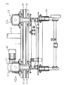
図8及び図9は、本発明の実施の形態2に係る非接触給電システムを用いた移動体システムに備えられた移動体2の構成を示す側面図及び正面図であり、図10は、非接触給電システムが備える給電線40、受電線70、及びピックアップコイル511及び供給コイル63を示す断面図である。
8 and 9 are a side view and a front view showing the configuration of the moving
レール1の側面にネジ留めされている取付板13の上部及び下部には、多数の棒状部材を用いてなる支持部材14,14,…及び支持部材15,15,…が、夫々略水平に並んで設けられている。
.. And
給電線40は、支持部材14,14,…の先端部に固定されることによって、レール1に沿って敷設されており、高周波電源装置4に接続されて(図11参照)、定電流を供給されている。また、受電線70は、支持部材15,15,…の先端部に固定されることによって、給電線40に並行に敷設されており、電源回生装置71に接続されている(図11参照)。
The
移動体2は、ピックアップコイル511、ピックアップコア513、供給コイル63及び供給コア613を備える非接触給電装置52を搭載してあり、非接触給電装置52にモータM1,M2,…を接続して(図11参照)、非接触給電装置52を介し、給電線40から駆動用の電力を得るよう構成されている。また、移動体2は、非接触給電装置52を介して、モータM1,M2,…が発生させた回生電力を受電線70に供給するよう構成されている。
The moving
受電線70に供給された回生電力は、電源回生装置71へ供給される。
The regenerative power supplied to the receiving
ピックアップコア513及び供給コア613は、ピックアップコイル511及び供給コイル63を巻装してあり、車体枠21のレール1側に、上下に並設して固定されている。
The
供給コア613は、断面形状がコの字状に形成された磁性体であり、供給コイル63を巻回してある柱部613cと、柱部613cの両端に夫々設けられた突起部613a,613bとを有する。
The
レール1に移動体2を載架する場合は、ピックアップコア513及び供給コア613が、給電線40,受電線70と所定の間隔を隔てて対面し、給電線40が突起部513a,513bの間に位置し、受電線70が突起部613a,613bの間に位置するよう配置する。
When the moving
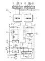
図11は、非接触給電システムが備える非接触給電装置52の構成を示す電気回路図である。
FIG. 11 is an electric circuit diagram illustrating a configuration of the non-contact
図中9は商用電源であり、商用電源9の出力を高周波電源装置4が整流し、平滑化し、10KHzの周波数を有する定電流に変換して、変換した交流定電流を給電線40へ出力する。
In the figure, reference numeral 9 denotes a commercial power source. The output of the commercial power source 9 is rectified and smoothed by the high frequency power supply device 4 and converted into a constant current having a frequency of 10 KHz, and the converted AC constant current is output to the
各移動体2に搭載してある非接触給電装置52は、受電回路5と給電回路6とを備える。
The non-contact
給電回路6(供給手段)は、供給制御回路60と、共振回路部61と、高周波インバータ62と、供給コイル63とを備え、供給制御回路60と高周波インバータ62とは、DCバスDBに接続されている。
The power supply circuit 6 (supply means) includes a
供給コイル63(供給部)は、受電線70に対し離隔配置されている。共振回路部61は、高周波インバータ62と供給コイル63とに接続されており、高周波インバータ62から共振回路部61へ交流電流が流入した場合、供給コイル63を介して、受電線70にその交流電流の周波数に等しい周波数を有する交流の電力が誘起されるよう構成してある。
The supply coil 63 (supply part) is spaced from the receiving
高周波インバータ62は、高周波インバータ62に入力される直流を平滑化する平滑コンデンサ623と、複数のトランジスタを用いてなるインバータ部621(第3スイッチ回路)とを備え、該インバータ部621の出力側が共振回路部61に接続されている。
The
供給制御回路60(第2制御回路)は、受電回路5の出力部の電圧Vを検出する検出部60aを備え、検出した電圧Vが第1電圧V1 以上である場合、高周波インバータ62のインバータ部621へ制御信号を伝送し、検出した電圧Vが第1電圧V1未満である場合、インバータ部621への制御信号の伝送を停止する。
Supply control circuit 60 (second control circuit), if provided with a detecting portion 60a for detecting the voltage V at the output of the receiving
供給制御回路60及び高周波インバータ62は、高周波インバータ62に直流の回生電力が供給された場合に供給された回生電力を交流に変換する手段である。
The
また、供給制御回路60は、高周波インバータ62内の電流を検出する電流センサ(CT)622の検出結果に応じて、高周波インバータ62から共振回路部61へ流出させる交流電流の大小を制御する。これによって、受電線70への供給量を制御する。本実施の形態では、検出した電圧Vが第1電圧V1 以上である場合、所定の電流値I1 を越える電流を検出したときに、インバータ部621への制御信号の伝送を停止する場合を例示する。
The
以上のような第1電圧V1 としては、受電回路の最大出力電圧Vs より大きく、非接触給電装置52の各機器、モータドライバD1,D2,…、及びモータM1,M2,…が使用可能である電圧の上限以下の電圧を用い、該第1電圧V1が、予め供給制御回路60に設定される。
The first voltage V 1 as described above is larger than the maximum output voltage V s of the power receiving circuit, and each device of the non-contact
高周波インバータ62は、制御信号が伝送された場合、受電回路5の出力部及びモータドライバD1,D2,…側から流入してきた直流電流を交流電流(例えば20KHzの高周波電流)に変換して共振回路部61へ流出させ(即ち供給制御回路60によって高周波インバータ62が入にされ)、制御信号を伝送されていない場合はその直流電流を遮断する(高周波インバータ62が断にされる)。
When the control signal is transmitted, the
図12は、非接触給電装置52の供給制御回路60の動作を示すフローチャートである。
FIG. 12 is a flowchart showing the operation of the
供給制御回路60は、まず、高周波インバータ62のインバータ部621への制御信号の伝送を停止する(S11)。即ち、移動体2の駆動開始前は、制御信号を伝送しない。このため、供給コイル63に交流が供給されず、このため、誘導結合が生じず、この結果、受電線70へも回生電力が供給されない。
The
移動体2の駆動開始後、供給制御回路60は、検出した電圧Vが、第1電圧V1 以上であるか否かを判定する(S12)。V≧V1 である場合(S12でYES)、供給制御回路60は、検出した電流Iが、所定の電流値I1以下であるか否かを判定する(S13)。I≦I1 である場合(S13でYES)、供給制御回路60は、インバータ部621へ制御信号を伝送する(S14)。このため、供給コイル63に交流が供給されて誘導結合が生じ、この結果、受電線70へ回生電力が供給される。
After the driving of the moving
S14の処理の完了後、供給制御回路60は、処理をS12へ戻す。
After the process of S14 is completed, the
供給制御回路60は、V<V1 である場合(S12でNO)、又は、I>I1 である場合(S13でNO)、処理をS11へ戻して、制御信号を伝送しているときは制御信号の伝送を停止し、制御信号を伝送していないときは、制御信号の伝送を行なわず、S12の処理を行なう。
When V <V 1 (NO in S12) or I> I 1 (NO in S13), the
以上のようにして、供給制御回路60は、検出部60aにて受電回路5の電圧Vを検出し、S12にて、検出した電圧Vと第1電圧V1 とを比較し、比較結果の高低に応じて、S14,S11にて、高周波インバータ62(インバータ部621)の入/断を制御する。
As described above, the
以上のような非接触給電装置52は、受電回路5の出力部の電圧Vが第1電圧V1 以上である場合、即ちモータM1,M2,…が回生電力を発生させ、モータドライバD1,D2,…が直流電流を出力している場合、供給制御回路60が高周波インバータ62を入にする。このとき、高周波インバータ62がモータドライバD1,D2,…から出力された直流電流を高周波の交流電流に変換して、変換した交流電流を共振回路部61へ出力し、共振回路部61へ出力された交流電流が、供給コイル63を介して受電線70に誘導起電力を発生させる。このようにして、回生電力が、交流電力として受電線70に供給される。即ち、受電線70が回生電力を受電する。
The non-contact
また、受電回路5の出力部の電圧Vが第1電圧V1 未満である場合、即ちモータM1,M2,…が回生電力を発生させていない場合、供給制御回路60が高周波インバータ62を断にする。このとき、高周波インバータ62が、受電回路5の出力部から出力された直流電流を遮断する。このため、回生電力が、受電線70に供給されない。
Further, when the voltage V at the output portion of the
受電線70は電源回生装置71に接続され、電源回生装置71が、商用電源9に接続されている。
The receiving
受電線70は、誘起された交流電流を、電源回生装置71へ伝送する。電源回生装置71は、図示しない電流センサ又は電圧センサが電流又は電圧を検出することによって、交流電流が伝送されてきたことを検出し、伝送された交流電流を、商用電源9へ給電するよう構成してある。即ち、受電線70は、受電した回生電力を電源回生装置71へ伝送し、電源回生装置71は、伝送された回生電力を、商用電源9へ給電する。このため、商用電源9に回生電力を回収させることができ、商用電源9を介して、回生電力を有効利用することができる。
The
以上のようにして、本実施の形態の非接触給電システムは、非接触給電装置52から商用電源9へ供給される回生電力の分だけ、省電力の効果を得ることができる(例えば、外部から買い入れる電力のコストを低減することができる)。
As described above, the contactless power supply system of the present embodiment can obtain a power saving effect by the amount of regenerative power supplied from the contactless
なお、本実施の形態の非接触給電システムにおいては、モータM1,M2,…へ給電すべき電力は、モータM1,M2,…が回生電力を発生させていない場合であっても、商用電源9から必要なだけ供給されるため、非接触給電装置52から商用電源9へ供給される回生電力の供給量は、安定的である必要はない。
In the non-contact power feeding system of the present embodiment, the power to be fed to the motors M1, M2,... Is the commercial power source 9 even when the motors M1, M2,. Therefore, the supply amount of the regenerative power supplied from the non-contact
また、本実施の形態においては、高周波インバータ62が、モータM1,M2,…側から受電した直流電流を、給電線40を流れる交流定電流の周波数(10KHz)とは異なる周波数(20KHz)の交流電流に変換する場合を例示したが、前記直流電流を、給電用交流電流の周波数に等しい周波数(10KHz)の交流電流に変換しても良い。
In the present embodiment, the high-
更に、供給制御回路60は、第1電圧V1 を発生させる基準電圧発生回路、及び、該基準電圧発生回路が発生させた電圧と受電回路5の出力部の電圧Vとの大小を比較し、比較結果に応じて所定の信号を出力する比較回路等で構成された検出部60aを用いてアナログ回路として構成しても良い。又は、受電回路5の出力部の電圧Vを検出する電圧センサである検出部60a、第1電圧V1を記憶するメモリ、及び、電圧センサの検出結果とメモリに記憶された電圧とを比較し、比較結果に応じて所定の信号を出力するCPU等を用いてデジタル回路として構成しても良い。
Further, the
(実施の形態 3.)
以下では、移動体システム(図1参照)に駆動用の電力を供給し、また、回生電力を回収して商用電源へ供給する非接触給電システム、及び該非接触給電システムを構成し、モータが発生させた回生電力を受電手段に供給する非接触給電装置53を例示する。また、本実施の形態では、非接触給電装置53から供給された回生電力を受電する受電手段として、給電線40を用いる場合を例示する。
(Embodiment 3.)
In the following, a driving power is supplied to a mobile system (see FIG. 1), a regenerative power is recovered and supplied to a commercial power source, and the non-contact power feeding system is configured to generate a motor. The non-contact
また、実施の形態1又は2に対応する部分には同一符号を付してそれらの説明を省略する。 Also, parts corresponding to those in the first or second embodiment are denoted by the same reference numerals, and description thereof is omitted.
図13は、本発明の実施の形態3に係る非接触給電システムを用いた移動体システムに備えられた移動体2の構成を示す側面図であり、図14は、非接触給電システムが備える給電線40及び供給コイル63を示す断面図である。
FIG. 13 is a side view showing the configuration of the moving
給電線40は、支持部材14,14,…の先端部に固定されることによって、レール1に沿って敷設されており、高周波電源装置4に接続されて(図15参照)、交流定電流が供給されている。
The
移動体2は、ピックアップコイル511、ピックアップコア513、供給コイル63、及び供給コア613を備える非接触給電装置53を搭載してあり、非接触給電装置53にモータM1,M2,…を接続して(図15参照)、非接触給電装置53を介し、給電線40から駆動用の電力を得るよう構成されている。また、移動体2は、非接触給電装置53を介して、モータM1,M2,…が発生させた回生電力を給電線40に供給するよう構成されている。
The moving
ピックアップコア513及び供給コア613は、ピックアップコイル511及び供給コイル63を巻装してあり、車体枠21のレール1側に、前後に並設して固定されている。
The
レール1に移動体2を載架する場合は、供給コア613(ピックアップコア513)が、給電線40と所定の間隔を隔てて対面し、給電線40が突起部613a,613b(突起部513a,513b)の間に位置するよう配置する。
When the moving
図15は、非接触給電システムが備える非接触給電装置53の構成を示す電気回路図である。
FIG. 15 is an electric circuit diagram illustrating a configuration of a non-contact
図中9は商用電源であり、商用電源9の出力を高周波電源装置4が整流し、平滑化し、10KHzの周波数を有する定電流に変換して、変換した定電流を給電線40へ出力する。
In the figure, reference numeral 9 denotes a commercial power source. The output of the commercial power source 9 is rectified and smoothed by the high frequency power supply device 4 and converted into a constant current having a frequency of 10 KHz, and the converted constant current is output to the
各移動体2に搭載してある非接触給電装置53は、受電回路5と給電回路6とを備える。
The non-contact
供給コイル63は、給電線40に対し離隔配置されている。共振回路部61は、高周波インバータ62と供給コイル63とに接続されており、高周波インバータ62から共振回路部61へ交流電流が流入した場合、供給コイル63を介して、その交流電流の周波数(20KHz)に等しい周波数を有する交流の電力が給電線40に誘起されるよう構成してある。
The
以上のような非接触給電装置53は、受電回路5の出力部の電圧Vが第1電圧V1 以上である場合、即ちモータM1,M2,…が回生電力を発生させ、モータドライバD1,D2,…が直流電流を出力している場合、供給制御回路60が高周波インバータ62を入にする。このとき、高周波インバータ62がモータドライバD1,D2,…から出力された直流電流を高周波の交流電流に変換して、変換した交流電流を共振回路部61へ出力し、共振回路部61へ出力された交流電流が、供給コイル63を介して給電線40に誘導起電力を発生させる。このようにして、回生電力が、交流電力として給電線40に供給される。即ち、給電線40が回生電力を受電する。
In the non-contact
給電線40には、高周波電源装置4から供給される10KHzの定電流が流れており、また、共振回路部61が給電線40に回生電力を供給した場合に、20KHzの交流電流(以下、回生交流電流と言う)が流れる。
A constant current of 10 KHz supplied from the high-frequency power supply device 4 flows through the
電源回生装置72は、給電線40を流れる回生交流電流の周波数(20KHz)と共振状態になるよう構成されている共振回路部720を備え、更に、商用電源9に接続してある。また、電源回生装置72は、共振回路部720に誘起された電力を受けて、共振回路部720に定電流が発生した場合、即ち回生電力を給電線40から受電した場合、受電した回生電力を、商用電源9へ給電するよう構成してある。即ち、給電線40は、受電した回生電力を伝送し、電源回生装置72は、共振回路部720を介して回生電力を受電し、受電した回生電力を、商用電源9へ給電する。このため、商用電源9に回生電力を回収させることができ、商用電源9を介して、回生電力を有効利用することができる。
The
なお、高周波電源装置4から給電線40へ供給される定電流の周波数と、回生交流電流の周波数とが等しい場合、給電回路6と電源回生装置72とを同期させる必要があるため、各周波数は、夫々異なることが望ましい。
In addition, when the frequency of the constant current supplied from the high frequency power supply device 4 to the
(実施の形態 4.)
以下では、移動体システム(図1参照)に駆動用の電力を供給し、また、回生電力を回収して高周波電源装置へ供給する非接触給電システム、及び該非接触給電システムを構成し、モータが発生させた回生電力を受電手段に供給する非接触給電装置52を例示する。また、本実施の形態では、非接触給電装置52から供給された回生電力を受電する受電手段として、受電線70を用いる場合を例示する。
(Embodiment 4.)
In the following, a non-contact power feeding system that supplies driving power to a mobile system (see FIG. 1), collects regenerative power and supplies the regenerated power to a high frequency power supply device, and the non-contact power feeding system is configured. The non-contact
また、実施の形態1又は2に対応する部分には同一符号を付してそれらの説明を省略する。 Also, parts corresponding to those in the first or second embodiment are denoted by the same reference numerals, and description thereof is omitted.
図16は、本発明の実施の形態4に係る非接触給電システムが備える高周波電源装置41及び電源回生装置73の構成を示す電気回路図である。
FIG. 16 is an electric circuit diagram showing configurations of the high frequency
図中41は高周波電源装置であり、高周波電源装置41は、交流電力を受電する交流入力部410と、ダイオードブリッジを用いてなる整流回路411と、平滑コンデンサを用いてなる平滑回路413とを備える。また、整流回路411と平滑回路413との間に、直流電力を受電する直流入力部412を備える。
In the figure,
更に、高周波電源装置41は、トランジスタを用いてなるインバータ部414と、インダクタ及びキャパシタを適宜配置してなるイミタンス変換部415と、交流電流を給電する交流出力部416とを備える。高周波電源装置41は、交流入力部410に商用電源9が接続されており、直流入力部412に電源回生装置73が接続されており、交流出力部416に給電線40が接続されている。
Furthermore, the high frequency
電源回生装置73は、交流電力を受電する交流入力部734と、ダイオードブリッジを用いてなる整流回路731と、平滑コンデンサを用いてなる平滑回路732と、外部へ直流電力を給電する直流出力部733とを備える。更に、高周波電源装置41は、交流入力部734と整流回路731との間に、急激な電圧の変化を緩和するためのコンデンサ730を備える。電源回生装置73は、交流入力部734に受電線70が接続されており、直流出力部733に高周波電源装置41が接続されている。
The
以上のような非接触給電システムは、受電線70が、非接触給電装置52が供給した回生電力を交流電力として受電し、受電した回生電力を電源回生装置73の交流入力部734へ伝送する。
In the non-contact power supply system as described above, the receiving
電源回生装置73は、交流入力部734へ入力された回生電力を、整流回路731で全波整流し、整流回路731が出力した全波整流波形を有する直流電流を平滑回路732で平滑し、直流出力部733から、高周波電源装置41の直流入力部412へ入力する。
The
高周波電源装置41は、商用電源9から交流入力部410へ入力された交流電力を整流回路411で全波整流し、整流回路411が出力した全波整流波形を有する直流電流、又は、該直流電流と、電源回生装置73から直流入力部412へ入力された直流電流とを平滑回路413で平滑し、平滑回路413の出力をインバータ部414で交流電流に変換し、インバータ部414が出力した交流電流をイミタンス変換部415で定電流に変換して、交流出力部416から給電線40へ給電する。即ち、電源回生装置73は、受電線70が受電した回生電力を、高周波電源装置41へ供給する。
The high-frequency
以上のようにして、高周波電源装置41に回生電力を回収させることができ、システム内部で回生電力を有効利用することができる。
As described above, the high-frequency
この場合、電源回生装置73は、平滑回路732の出力である直流電流を、直接、高周波電源装置41へ入力することができる。このため、その直流電流を、一旦交流電流に変換して商用電源9へ供給し、商用電源9から、交流電流として高周波電源装置41へ入力する必要がなく、電源回生装置73の回路を簡易に構成することができる。
In this case, the
更に、電源回生装置73は、直流出力部733と平滑回路732との間に、供給量制御回路735を介して、抵抗器736を備える。供給量制御回路735は、平滑回路732の電圧Vo 、即ち、直流出力部733から出力される直流の電圧Voを検出し、検出結果が所定の電圧以上である場合は、平滑回路732から出力される直流電流を抵抗器736へ流入させる。
Further, the
前記所定の電圧は、高周波電源装置41(直流入力部412)の耐圧以下の電圧である。このため、供給量制御回路735は、電源回生装置73の出力電圧Vo が所定の電圧以上である場合に、回収した回生電力を、抵抗器736で熱として消費させることによって、電源回生装置73の出力電圧Voが高周波電源装置41に対して過電圧になることを防止している。
The predetermined voltage is a voltage equal to or lower than the withstand voltage of the high-frequency power supply device 41 (DC input unit 412). For this reason, the supply
なお、高周波電源装置41に回生電力を回収させるだけでなく、実施の形態2のように、商用電源9にも回生電力を回収させるよう構成しても良い。この場合、システム内部へ電力を供給する必要がない場合(例えばシステム内部の全てのモータが回生電力を発生させている場合)、回生電力を商用電源9へ回収させて、商用電源9に接続されている他の非接触給電システム又は負荷等で有効利用することができる。
Not only the high-frequency
本実施の形態においては、高周波電源装置41へ過剰な電圧の回生電力を供給してしまうことを防止する抵抗器736及び供給量制御回路735を、電源回生装置73に備えており、非接触給電装置52には備えていないため、非接触給電装置52が抵抗器736及び供給量制御回路735を備える分だけ大型化することが防止され(非接触給電装置52の省スペース化)、また、非接触給電装置52での発熱が小さくなり、熱による悪影響が低減される。
In the present embodiment, the
また、高周波電源装置41は、一般に地上に設置されるため、抵抗器736及び供給量制御回路735を備えるスペースの制約が少なくなり、抵抗器736及び供給量制御回路735による制動能力を十分に大きく取ることができる。
In addition, since the high frequency
なお、電源回生装置73から高周波電源装置41へ回生電力を供給する構成のみならず、電源回生装置73の抵抗器736にて全ての回生電力を熱として消費する構成も考えられる。
In addition to the configuration in which the regenerative power is supplied from the
(実施の形態 5.)
図17は、本発明の実施の形態5に係る非接触給電システムが備える非接触給電装置55の構成を示す電気回路図である。以下では、実施の形態1に対応する部分には同一符号を付してそれらの説明を省略する。
(
FIG. 17 is an electric circuit diagram showing a configuration of a non-contact
非接触給電装置55は、実施の形態1の非接触給電装置51に対応し、非接触給電装置51が備える蓄電部8の代わりに、蓄電部89を備える。
The non-contact
蓄電部89は、充放電制御回路84と、スーパーコンデンサを用いてなる蓄電回路86と、インダクタ85と、トランジスタ871及びダイオード872を有する充電回路87と、トランジスタ881及びダイオード882を有する放電回路88を備え、蓄電回路86は、インダクタ85と、充電回路87及び放電回路88の夫々とを介して、DCバスDBに接続されている。また、充放電制御回路84も、DCバスDBに接続されている。
The
充放電制御回路84(第1制御回路)は、受電回路5の出力部の電圧Vを検出する検出部84aと、蓄電回路86の電圧Vc を検出する検出部84bと、蓄電回路86に対し流入出する電流Icを検出する電流センサ(CT)841とを備える。
The charge / discharge control circuit 84 (first control circuit) has a detection unit 84 a that detects the voltage V of the output unit of the
蓄電回路86の定格電圧は、例えば54Vであり、受電回路5の最大電圧及び回生電力の最大電圧(例えば360V)より小さい。また、蓄電回路86を充電する場合、蓄電回路86の定格電圧より適宜の値だけ小さい電圧(例えば50V)を有する直流の定電流を蓄電回路86に流入させる必要がある。蓄電部89は充電回路87及び放電回路88等で構成された昇圧降圧回路であり、蓄電回路86に対して降圧して充電し、蓄電回路86から放電された電力を昇圧してモータM1,M2,…側へ出力する。
The rated voltage of the
以上のような非接触給電装置55は、実施の形態1の非接触給電装置51と同様に、蓄電回路86に対して回生電力を充放電することによって、回生電力を回収し、移動体2内で有効に利用することができる。
The non-contact
なお、充放電制御回路84は、実施の形態1の充放電制御回路80と同様にしてアナログ回路として構成しても良く、デジタル回路として構成しても良い。
Note that the charge /
4,41高周波電源装置
40 給電線(給電線,受電手段)
5 受電回路
51,52,53,55 非接触給電装置
6 給電回路(供給手段)
60 充放電制御回路(第1制御回路)
62 高周波インバータ
621 インバータ部(第3スイッチ回路)
63 供給コイル(供給部)
70 受電線(受電手段)
71,72,73 電源回生装置
80,84 充放電制御回路(第2制御回路)
81,87 充電回路(第1スイッチ回路)
82,88 放電回路(第2スイッチ回路)
83,86 蓄電回路
9 商用電源
M1,M2 モータ
4, 41 high frequency
5
60 charge / discharge control circuit (first control circuit)
62
63 Supply coil (supply unit)
70 Power receiving line (power receiving means)
71, 72, 73
81,87 Charging circuit (first switch circuit)
82,88 Discharge circuit (second switch circuit)
83,86 Power storage circuit 9 Commercial power supply M1, M2 Motor
Claims (10)
モータの回生電力を蓄電する蓄電回路を備えることを特徴とする非接触給電装置。 In a non-contact power supply device including a power receiving circuit that receives power from a power supply line through which an alternating current flows in a non-contact manner and supplies power to the motor
A non-contact power feeding device comprising a power storage circuit that stores regenerative power of a motor.
前記受電回路の電圧を検出する手段、検出した電圧と所定の第1電圧とを比較する手段、及び、比較結果の高/低に応じて、前記第1スイッチ回路の入/断を制御する手段を有する第1制御回路とを備えることを特徴とする請求項1に記載の非接触給電装置。 A first switch circuit for switching on and off the supply of regenerative power to the storage circuit;
Means for detecting the voltage of the power receiving circuit, means for comparing the detected voltage with a predetermined first voltage, and means for controlling on / off of the first switch circuit according to the comparison result high / low The non-contact electric power feeder of Claim 1 provided with the 1st control circuit which has.
前記第1制御回路は、検出した電圧と前記第1電圧より低い第2電圧とを比較する手段、検出した電圧が前記第2電圧以下である場合、前記第2スイッチ回路を入にする手段、及び、検出した電圧が前記第1電圧以上である場合、前記第2スイッチ回路を断にする手段を更に有することを特徴とする請求項2に記載の非接触給電装置。 A second switch circuit for switching on and off the discharge from the storage circuit;
Means for comparing the detected voltage with a second voltage lower than the first voltage; means for turning on the second switch circuit when the detected voltage is less than or equal to the second voltage; The contactless power feeding device according to claim 2, further comprising means for disconnecting the second switch circuit when the detected voltage is equal to or higher than the first voltage.
モータの回生電力を外部の受電手段へ供給する供給手段を備えることを特徴とする非接触給電装置。 In a non-contact power supply device that receives power from a power supply line through which an alternating current flows in a non-contact manner and supplies power to the motor,
A non-contact power feeding apparatus comprising: a supply unit that supplies regenerative power of a motor to an external power receiving unit.
前記供給手段は、
前記受電手段に誘導結合すべき供給部と、
該供給部への回生電力の供給を入断する第3スイッチ回路と
を備えることを特徴とする請求項5に記載の非接触給電装置。 The power receiving means is an electric wire,
The supply means includes
A supply unit to be inductively coupled to the power receiving means;
A non-contact power feeding device according to claim 5, further comprising: a third switch circuit that interrupts the supply of regenerative power to the supply unit.
前記供給手段は、
前記受電回路の電圧を検出する手段、及び、該手段が検出した電圧の高/低に応じて、前記第3スイッチ回路の入/断を制御する手段を有する第2制御回路を備えることを特徴とする請求項6に記載の非接触給電装置。 Equipped with a power receiving circuit for receiving power from a power supply line through which alternating current flows in a non-contact manner and supplying power to the motor,
The supply means includes
And a second control circuit having means for detecting the voltage of the power receiving circuit and means for controlling on / off of the third switch circuit in accordance with high / low of the voltage detected by the means. The contactless power supply device according to claim 6.
前記非接触給電装置は請求項5乃至7の何れか一項に記載の非接触給電装置であり、
該非接触給電装置が供給する回生電力を受電する受電手段と、
該受電手段が受電した回生電力を、前記商用電源又は前記電源装置へ供給する手段と
を備えることを特徴とする非接触給電システム。 A power supply device that receives power from a commercial power source and outputs an alternating current, a power supply line through which the alternating current output from the power supply device flows, and a non-contact power supply device that receives power from the power supply line in a contactless manner and supplies power to the motor In the contactless power supply system provided,
The contactless power supply device is the contactless power supply device according to any one of claims 5 to 7,
Power receiving means for receiving regenerative power supplied by the contactless power supply device;
Means for supplying regenerative power received by the power receiving means to the commercial power source or the power supply device.
前記非接触給電装置は請求項5乃至7の何れか一項に記載の非接触給電装置であり、
該非接触給電装置が供給する回生電力を受電する受電手段は前記給電線であり、
該給電線が受電した回生電力を、前記商用電源又は前記電源装置へ供給する手段を備えることを特徴とする非接触給電システム。 A power supply device that receives power from a commercial power source and outputs an alternating current, a power supply line through which the alternating current output from the power supply device flows, and a non-contact power supply device that receives power from the power supply line in a contactless manner and supplies power to the motor In the contactless power supply system provided,
The contactless power supply device is the contactless power supply device according to any one of claims 5 to 7,
The power receiving means for receiving regenerative power supplied by the contactless power supply device is the power supply line,
A non-contact power supply system comprising means for supplying regenerative power received by the power supply line to the commercial power supply or the power supply apparatus.
Priority Applications (1)
| Application Number | Priority Date | Filing Date | Title |
|---|---|---|---|
| JP2004106833A JP2005295680A (en) | 2004-03-31 | 2004-03-31 | Noncontact power supply apparatus and noncontact power supply system |
Applications Claiming Priority (1)
| Application Number | Priority Date | Filing Date | Title |
|---|---|---|---|
| JP2004106833A JP2005295680A (en) | 2004-03-31 | 2004-03-31 | Noncontact power supply apparatus and noncontact power supply system |
Publications (1)
| Publication Number | Publication Date |
|---|---|
| JP2005295680A true JP2005295680A (en) | 2005-10-20 |
Family
ID=35328008
Family Applications (1)
| Application Number | Title | Priority Date | Filing Date |
|---|---|---|---|
| JP2004106833A Pending JP2005295680A (en) | 2004-03-31 | 2004-03-31 | Noncontact power supply apparatus and noncontact power supply system |
Country Status (1)
| Country | Link |
|---|---|
| JP (1) | JP2005295680A (en) |
Cited By (6)
| Publication number | Priority date | Publication date | Assignee | Title |
|---|---|---|---|---|
| KR101056166B1 (en) | 2009-12-23 | 2011-08-11 | 한국과학기술원 | Power supply control system of electric vehicle with non-contact magnetic induction charging |
| JP2012257395A (en) * | 2011-06-09 | 2012-12-27 | Toyota Motor Corp | Non-contact power receiving apparatus and vehicle including the same, non-contact power transmission apparatus, and non-contact power transmission system |
| JP2013232996A (en) * | 2012-04-27 | 2013-11-14 | Toshiba Schneider Inverter Corp | Inverter device and inverter power receiving device |
| JP2014039423A (en) * | 2012-08-20 | 2014-02-27 | Toshiba Schneider Inverter Corp | Inverter device, inverter option device, and external power-supply device |
| WO2014038017A1 (en) * | 2012-09-05 | 2014-03-13 | 富士機械製造株式会社 | Non-contact power supply device |
| JP2018183012A (en) * | 2017-04-21 | 2018-11-15 | 東洋電機製造株式会社 | Power converter |
-
2004
- 2004-03-31 JP JP2004106833A patent/JP2005295680A/en active Pending
Cited By (9)
| Publication number | Priority date | Publication date | Assignee | Title |
|---|---|---|---|---|
| KR101056166B1 (en) | 2009-12-23 | 2011-08-11 | 한국과학기술원 | Power supply control system of electric vehicle with non-contact magnetic induction charging |
| JP2012257395A (en) * | 2011-06-09 | 2012-12-27 | Toyota Motor Corp | Non-contact power receiving apparatus and vehicle including the same, non-contact power transmission apparatus, and non-contact power transmission system |
| JP2013232996A (en) * | 2012-04-27 | 2013-11-14 | Toshiba Schneider Inverter Corp | Inverter device and inverter power receiving device |
| JP2014039423A (en) * | 2012-08-20 | 2014-02-27 | Toshiba Schneider Inverter Corp | Inverter device, inverter option device, and external power-supply device |
| WO2014038017A1 (en) * | 2012-09-05 | 2014-03-13 | 富士機械製造株式会社 | Non-contact power supply device |
| CN104604089A (en) * | 2012-09-05 | 2015-05-06 | 富士机械制造株式会社 | Non-contact power supply device |
| JPWO2014038017A1 (en) * | 2012-09-05 | 2016-08-08 | 富士機械製造株式会社 | Contactless power supply |
| CN104604089B (en) * | 2012-09-05 | 2017-07-21 | 富士机械制造株式会社 | Contactless power supply device |
| JP2018183012A (en) * | 2017-04-21 | 2018-11-15 | 東洋電機製造株式会社 | Power converter |
Similar Documents
| Publication | Publication Date | Title |
|---|---|---|
| JP3900822B2 (en) | A power supply circuit for a mobile unit that is powered without contact | |
| JP3911621B2 (en) | Railway system for battery-powered trains | |
| KR101214295B1 (en) | Power feeding device and rubber tired gantry crane including the same | |
| TWI625257B (en) | Tram control | |
| WO2009123041A1 (en) | Crane system | |
| CN106663528A (en) | Inductive power system suitable for electric vehicles | |
| KR20150050952A (en) | Wireless Power Transmission System for Tram Vehicle | |
| KR20110058669A (en) | Non-contact feeding method between driving system and driving lane | |
| CN108059042A (en) | Electrical autonomous elevator device | |
| US9083194B2 (en) | Battery charging system and train | |
| JP2010187471A (en) | Non-contact power receiving apparatus and automated guided vehicle | |
| JP2018107907A (en) | Transportation carriage | |
| JP4576465B2 (en) | Charging method and charging system for overhead line-less traffic vehicle | |
| EP3246195A1 (en) | Charge/discharge control device | |
| JP4415874B2 (en) | Charge and discharge method for transportation system | |
| JP2012175803A (en) | Railway system equipped with power storage means | |
| CN114867628B (en) | Method for operating an electric vehicle and electric vehicle | |
| KR20180092203A (en) | Energy storage apparatus to stabilize power based on wireless power supply for railway vehicles | |
| JP2005295680A (en) | Noncontact power supply apparatus and noncontact power supply system | |
| JP3768982B2 (en) | Intermittent power supply type electric vehicle system and electric vehicle | |
| KR20160082945A (en) | wireless charging monorail system | |
| JP2010089855A (en) | Crane device and control method of crane device | |
| JP2003220859A (en) | DC electric power storage device and railway electromechanical system | |
| JP7786421B2 (en) | Charging system for electric vehicles and computer program | |
| KR100797115B1 (en) | Induced Sudden Charging System for Electric Rail Car |