JP2005295675A - Cylinder type linear motor - Google Patents
Cylinder type linear motor Download PDFInfo
- Publication number
- JP2005295675A JP2005295675A JP2004106602A JP2004106602A JP2005295675A JP 2005295675 A JP2005295675 A JP 2005295675A JP 2004106602 A JP2004106602 A JP 2004106602A JP 2004106602 A JP2004106602 A JP 2004106602A JP 2005295675 A JP2005295675 A JP 2005295675A
- Authority
- JP
- Japan
- Prior art keywords
- magnetic pole
- divided
- core
- portions
- pole portions
- Prior art date
- Legal status (The legal status is an assumption and is not a legal conclusion. Google has not performed a legal analysis and makes no representation as to the accuracy of the status listed.)
- Granted
Links
- 238000004804 winding Methods 0.000 claims abstract description 106
- 230000005284 excitation Effects 0.000 claims description 41
- 229910000831 Steel Inorganic materials 0.000 claims description 19
- 239000010959 steel Substances 0.000 claims description 19
- 239000000470 constituent Substances 0.000 claims description 10
- 238000010030 laminating Methods 0.000 claims description 8
- 125000006850 spacer group Chemical group 0.000 claims description 5
- 230000002093 peripheral effect Effects 0.000 claims description 3
- 239000000696 magnetic material Substances 0.000 claims description 2
- XEEYBQQBJWHFJM-UHFFFAOYSA-N Iron Chemical compound [Fe] XEEYBQQBJWHFJM-UHFFFAOYSA-N 0.000 abstract description 16
- 229910052742 iron Inorganic materials 0.000 abstract description 8
- 238000004519 manufacturing process Methods 0.000 abstract description 8
- 230000011218 segmentation Effects 0.000 description 7
- 239000000306 component Substances 0.000 description 3
- 229910000576 Laminated steel Inorganic materials 0.000 description 2
- 238000013459 approach Methods 0.000 description 1
- 239000008358 core component Substances 0.000 description 1
- 230000003247 decreasing effect Effects 0.000 description 1
- 230000004907 flux Effects 0.000 description 1
- XWHPIFXRKKHEKR-UHFFFAOYSA-N iron silicon Chemical compound [Si].[Fe] XWHPIFXRKKHEKR-UHFFFAOYSA-N 0.000 description 1
- 238000003754 machining Methods 0.000 description 1
- 239000000463 material Substances 0.000 description 1
- 229920003002 synthetic resin Polymers 0.000 description 1
- 239000000057 synthetic resin Substances 0.000 description 1
Images

Landscapes
- Iron Core Of Rotating Electric Machines (AREA)
- Linear Motors (AREA)
Abstract
Description
本発明は、シリンダ型リニアモータに関するものである。 The present invention relates to a cylinder type linear motor.
特開2001−286122号公報(特許文献1)では、筒状の磁極面形成部を備えた複数の円環状のコア分割体を可動子の運動方向に組み合わせて電機子コアを構成し、隣り合うコア分割体の間に可動子の周方向に巻回された環状巻線を配置するシリンダ型リニアモータが示されている。このシリンダ型リニアモータでは、固定子の可動子を囲む周方向全体に発生する磁力を利用するため、固定子側の推力作用面積を大きくして、モータの推力を高めることができる。
しかしながら、従来のリニアモータで用いる環状のコア分割体は、筒状の磁極面形成部を備えた複雑な形状を有しているため、ケイ素鉄材料に削り出し加工を施して形成している。そのため、電機子コアの製造コストが高くなる上、渦電流による鉄損が大きくなる。また、設計の自由度が低いという問題があった。 However, since the annular core divided body used in the conventional linear motor has a complicated shape including a cylindrical magnetic pole surface forming portion, it is formed by machining a silicon iron material. Therefore, the manufacturing cost of the armature core increases, and the iron loss due to eddy current increases. There is also a problem that the degree of freedom in design is low.
本発明の目的は、電機子コアの製造コストを低くし、鉄損を少なくして、しかも、設計の自由度を高くできるシリンダ型リニアモータを提供することにある。 An object of the present invention is to provide a cylinder type linear motor that can reduce the manufacturing cost of an armature core, reduce iron loss, and increase the degree of freedom in design.
本発明の他の目的は、励磁巻線を容易に巻装できるシリンダ型リニアモータを提供することにある。 Another object of the present invention is to provide a cylinder type linear motor in which an excitation winding can be easily wound.
本願発明が改良の対象とするシリンダ型リニアモータは、永久磁石によって構成されるN極とS極とが交互に直線状に並んで構成される永久磁石磁極部材と、N極とS極とが交互に並ぶ方向に並び且つ永久磁石磁極部材の周囲をそれぞれ囲む3n個(nは自然数)の環状の磁極部を備えた電機子コアと、電機子コアに装着されて隣り合う二つの環状の磁極部が異なる極性に励磁されるように3n個の磁極部をそれぞれ励磁する複数の励磁巻線とを有する電機子とを備えている。そして、永久磁石磁極部材及び電機子の一方が可動子となり他方が固定子となる構造を有している。本発明では、電機子コアは、永久磁石磁極部材の周方向に順番に組み合わされる第1〜第6の分割コアから構成し、第1〜第6の分割コアは、電機子コアの環状のヨークの一部を構成するヨーク構成部と、1つの励磁巻線が巻装される巻線巻装部と、励磁巻線により同じ極性に励磁されるn個の環状の磁極部の半部を構成するn個の分割磁極部とをそれぞれ備えている。また、第1〜第6の分割コアは、それぞれ第1の種類の複数枚の鋼板が積層されて構成されヨーク構成部及び巻線巻装部の一部を構成する2n個の第1の分割コア部分ユニットと、第2の種類の複数枚の鋼板が積層されて構成されてヨーク構成部及び巻線巻装部の一部並びに1つの分割磁極部を構成するn個の第2の分割コア部分ユニットとを積層して構成する。そして、第1の分割コアのn個の分割磁極部と第4の分割コアのn個の分割磁極部とを組み合せてn個の磁極部からなる第1の磁極部グループを構成し、第2の分割コアのn個の分割磁極部と第5の分割コアのn個の分割磁極部とを組み合わせてn個の磁極部からなる第2の磁極部グループを構成し、第3の分割コアのn個の分割磁極部と第6の分割コアのn個の分割磁極部とが組み合わせてn個の磁極部からなる第3の磁極部グループを構成する。また、第1及び第4の分割コアにおいて用いられる2n個の第1の分割コア部分ユニット及びn個の第2の分割コア部分ユニットは、それぞれ第1及び第4の分割コアが組み合わされて第1の磁極部グループが完成した状態で、一端側に第2の分割コア部分ユニットの一つが位置し且つ他端側に第1の分割コア部分ユニットの1つが位置し、第1の分割コア部分ユニットの内側に、第2の磁極部グループの1つの磁極部と第3の磁極部グループの1つの磁極部とが第1の分割コア部分ユニットと接触しない状態で位置するように定める。第2及び第5の分割コアにおいて用いられる2n個の第1の分割コア部分ユニット及びn個の第2の分割コア部分ユニットは、それぞれ第2及び第5の分割コアが組み合わされて第2の磁極部グループが完成した状態で、両端にそれぞれ1個の第1の分割コア部分ユニットが位置し、両端に位置する一方の第1の分割コア部分ユニットの内側に第1の磁極部グループに含まれる1つの磁極部が一方の第1の分割コア部分ユニットと接触しない状態で位置し、両端に位置する他方の第1の分割コア部分ユニットの内側に第3の磁極部グループに含まれる1つの磁極部が他方の第1の分割コア部分ユニットと接触しない状態で位置し、他の第1の分割コア部分ユニットの内側に、第1の磁極部グループの1つの磁極部と第3の磁極部グループの1つの磁極部とが第1の分割コア部分ユニットと接触しない状態で位置するように定める。第3及び第6の分割コアにおいて用いられる2n個の第1の分割コア部分ユニット及びn個の第2の分割コア部分ユニットは、それぞれ第3及び第6の分割コアが組み合わされて第3の磁極部グループが完成した状態で、一端側に第1の分割コア部分ユニットの1つのが位置し他端側に第2の分割コア部分ユニットの一つが位置し、第1の分割コア部分ユニットの内側に、第1の磁極部グループの1つの磁極部と第2の磁極部グループの1つの磁極部とが第1の分割コア部分ユニットと接触しない状態で位置するように定める。 The cylinder type linear motor to be improved by the present invention has a permanent magnet magnetic pole member composed of N poles and S poles composed of permanent magnets arranged in a straight line alternately, and N poles and S poles. An armature core having 3n (n is a natural number) annular magnetic pole portions arranged in an alternating direction and surrounding each of the permanent magnet magnetic pole members, and two annular magnetic poles mounted adjacent to the armature core And an armature having a plurality of exciting windings for exciting the 3n magnetic pole portions so that the portions are excited with different polarities. One of the permanent magnet magnetic pole member and the armature is a mover and the other is a stator. In the present invention, the armature core is composed of first to sixth divided cores that are sequentially combined in the circumferential direction of the permanent magnet magnetic pole member, and the first to sixth divided cores are annular yokes of the armature core. The yoke component that constitutes a part of the coil, the winding part on which one excitation winding is wound, and the half part of n annular magnetic poles that are excited to the same polarity by the excitation winding And n divided magnetic pole portions. Each of the first to sixth divided cores is formed by laminating a plurality of first-type steel plates, and 2n first divided cores constituting a part of the yoke constituent part and the winding winding part. N second divided cores that are configured by laminating a core part unit and a plurality of second-type steel plates to constitute a yoke component, a part of a winding winding part, and one divided magnetic pole part The partial unit is laminated. Then, a first magnetic pole portion group composed of n magnetic pole portions is formed by combining the n divided magnetic pole portions of the first divided core and the n divided magnetic pole portions of the fourth divided core. The n divided magnetic pole portions of the divided core and the n divided magnetic pole portions of the fifth divided core are combined to form a second magnetic pole portion group consisting of n magnetic pole portions, and the third divided core The n divided magnetic pole portions and the n divided magnetic pole portions of the sixth divided core are combined to form a third magnetic pole portion group including n magnetic pole portions. Further, 2n first divided core partial units and n second divided core partial units used in the first and fourth divided cores are combined with the first and fourth divided cores, respectively. In a state in which one magnetic pole part group is completed, one of the second divided core part units is located on one end side and one of the first divided core part units is located on the other end side, and the first divided core part It is determined that one magnetic pole part of the second magnetic pole part group and one magnetic pole part of the third magnetic pole part group are positioned inside the unit without contacting the first split core partial unit. The 2n first divided core partial units and n second divided core partial units used in the second and fifth divided cores are obtained by combining the second and fifth divided cores, respectively. In a state where the magnetic pole part group is completed, one first divided core partial unit is located at each end, and the first magnetic pole part group is included inside one of the first divided core partial units located at both ends. One magnetic pole part is located in a state where it does not come into contact with one first divided core partial unit, and one of the first magnetic core parts included in the third magnetic pole part group is located inside the other first divided core partial unit located at both ends. The magnetic pole portion is positioned in a state where it does not contact the other first divided core partial unit, and one magnetic pole portion and a third magnetic pole portion of the first magnetic pole portion group are disposed inside the other first divided core partial unit. Group 1 Defining a magnetic pole portion is to be positioned in a state not in contact with the first divided core unit. The 2n first divided core partial units and n second divided core partial units used in the third and sixth divided cores are obtained by combining the third and sixth divided cores, respectively. In a state where the magnetic pole part group is completed, one of the first divided core partial units is located on one end side, and one of the second divided core partial units is located on the other end side. It is determined that one magnetic pole part of the first magnetic pole part group and one magnetic pole part of the second magnetic pole part group are positioned in a state where they are not in contact with the first split core partial unit.
本発明のシリンダ型リニアモータでは、永久磁石磁極部材の周方向に順番に組み合わされる第1〜第6の分割コアから電機子コアを構成し、励磁巻線が巻装された第1及び第4の分割コアの巻線巻装部に接続されたn個の環状の磁極部と、励磁巻線が巻装された第2及び第5の分割コアの巻線巻装部に接続されたn個の環状の磁極部と、励磁巻線が巻装された第3及び第6の分割コアの巻線巻装部に接続されたn個の環状の磁極部とを交互に順次並べて配置して、電機子コアの3n個の環状の磁極部を構成している。このため、本発明では、環状の磁極部を形成した状態で永久磁石磁極部材の周方向と直交する方向に励磁巻線を巻装でき、励磁巻線の配置スペースを永久磁石磁極部材の周方向と直交する方向に延ばすことができる。そのため、環状の磁極部を設けても、第1〜第6の分割コアの横断面の形状(永久磁石磁極部材の横断面と同じ方向に切断した形状)を同一形状にでき、複数枚の鋼板を積層して第1〜第6の分割コアを構成することができる。その結果、電機子コアの製造コストを低くし、鉄損を少なくできる。しかも、鋼板の枚数を調整することにより分割コアの厚み寸法を変更できるので、電機子コアの設計の自由度を高くすることができる。 In the cylinder type linear motor of the present invention, the first and fourth armature cores are constituted by the first to sixth divided cores combined in order in the circumferential direction of the permanent magnet magnetic pole member, and the excitation winding is wound thereon. N ring-shaped magnetic pole portions connected to the winding winding portion of the split core, and n pieces connected to the winding winding portions of the second and fifth split cores wound with the excitation winding The annular magnetic pole portions and the n annular magnetic pole portions connected to the winding winding portions of the third and sixth divided cores around which the excitation windings are wound are alternately arranged in order, 3n annular magnetic pole portions of the armature core are formed. For this reason, in the present invention, the excitation winding can be wound in a direction orthogonal to the circumferential direction of the permanent magnet magnetic pole member with the annular magnetic pole portion formed, and the space for arranging the excitation winding is set in the circumferential direction of the permanent magnet magnetic pole member. It is possible to extend in a direction orthogonal to. Therefore, even if an annular magnetic pole part is provided, the shape of the cross section of the first to sixth split cores (the shape cut in the same direction as the cross section of the permanent magnet magnetic pole member) can be made the same shape, and a plurality of steel plates The first to sixth divided cores can be configured by stacking layers. As a result, the manufacturing cost of the armature core can be reduced and the iron loss can be reduced. And since the thickness dimension of a division | segmentation core can be changed by adjusting the number of steel plates, the freedom degree of design of an armature core can be made high.
また、本発明では、対向する2つの分割コアの分割磁極部を組み合せて磁極部を形成するため、励磁巻線を巻装した分割コアの分割磁極部をそれぞれ適宜に組み合わせて電機子を作ることができる。そのため、分割コアを組み合わせる前の段階で分割コアの巻線巻装部に励磁巻線を巻装でき、励磁巻線を容易に巻装することができる。 Further, in the present invention, since the magnetic pole portions are formed by combining the divided magnetic pole portions of the two divided cores facing each other, the armature is formed by appropriately combining the divided magnetic pole portions of the divided core around which the excitation winding is wound. Can do. Therefore, the excitation winding can be wound around the winding portion of the split core before the split cores are combined, and the excitation winding can be easily wound.
第1の磁極部グループのn個の磁極部、第2の磁極部グループのn個の磁極部及び第3の磁極部グループのn個の磁極部は互いに非接触状態になるように各分割コアの第1の分割コアユニットの厚みを定めるのが好ましい。例えば、第1の分割コアユニットの厚みを第2の分割コアユニットの厚みより薄くすればよい。このようにすれば、積層鋼板の枚数を調整するだけで、簡単に磁極部グループの磁極部の非接触化を図ることができる。 Each of the split cores so that the n magnetic pole portions of the first magnetic pole portion group, the n magnetic pole portions of the second magnetic pole portion group, and the n magnetic pole portions of the third magnetic pole portion group are not in contact with each other. It is preferable to determine the thickness of the first divided core unit. For example, the thickness of the first divided core unit may be made thinner than the thickness of the second divided core unit. If it does in this way, the non-contact of the magnetic pole part of a magnetic pole part group can be easily achieved only by adjusting the number of laminated steel plates.
ヨーク構成部は円弧状を呈するように構成し、環状のヨークは円筒状をなすように構成することができる。このようにすれば、電機子コアの占有体積を小さくできる。 The yoke component can be configured to have an arc shape, and the annular yoke can be configured to have a cylindrical shape. In this way, the occupied volume of the armature core can be reduced.
本願の他の発明が改良の対象とするシリンダ型リニアモータは、永久磁石によって構成されるN極とS極とが交互に直線状に並んで構成される永久磁石磁極部材と、N極とS極とが交互に並ぶ方向に並び且つ永久磁石磁極部材の周囲をそれぞれ囲む3n個(nは自然数)の環状の磁極部を備えた電機子コアと、電機子コアに装着されて隣り合う二つの環状の磁極部が異なる極性に励磁されるように3n個の磁極部をそれぞれ励磁する複数の励磁巻線とを有する電機子とを備えている。そして、永久磁石磁極部材及び電機子の一方が可動子となり他方が固定子となる。本発明では、電機子コアは、複数枚の環状の鋼板が積層されて構成された3n個の環状の磁極部からなる磁極部構成体と、複数枚の鋼板が積層されて構成され、内側に第1〜第6の励磁巻線がそれぞれ巻装される第1〜第6の突極部が周方向に等しい間隔をあけて配置された構造を有するコア本体とを備えている。そして、3n個の環状の磁極部に含まれるn個の磁極部が、第1及び第4の突極部に結合されて同じ極性に励磁される第1の磁極部グループを構成し、3n個の環状の磁極部に含まれる他のn個の磁極部が、第2及び第5の突極部に結合されて同じ極性に励磁される第2の磁極部グループを構成し、3n個の環状の磁極部に含まれる残りのn個の磁極部が、第3及び第6の突極部に結合されて同じ極性に励磁される第3の磁極部グループを構成するようにコア本体の内側に3n個の環状の磁極部が配置されている。 A cylinder type linear motor to be improved by another invention of the present application includes a permanent magnet magnetic pole member composed of permanent magnets and N poles and S poles alternately arranged in a straight line, and N poles and S poles. An armature core having 3n (n is a natural number) annular magnetic pole portions arranged in a direction in which the poles are alternately arranged and surrounding each of the permanent magnet magnetic pole members, and two adjacent armature cores mounted on the armature core And an armature having a plurality of exciting windings for exciting the 3n magnetic pole portions so that the annular magnetic pole portions are excited with different polarities. One of the permanent magnet magnetic pole member and the armature is a mover, and the other is a stator. In the present invention, the armature core is formed by laminating a plurality of annular steel plates and a magnetic pole portion structure composed of 3n annular magnetic pole portions, and a plurality of steel plates being laminated. And a core main body having a structure in which first to sixth salient pole portions around which first to sixth exciting windings are wound are arranged at equal intervals in the circumferential direction. Then, the n magnetic pole portions included in the 3n annular magnetic pole portions are coupled to the first and fourth salient pole portions to form a first magnetic pole portion group excited by the same polarity, and 3n The other n magnetic pole portions included in the annular magnetic pole portion constitute a second magnetic pole portion group that is coupled to the second and fifth salient pole portions and is excited to the same polarity, thereby forming 3n annular magnetic pole portions. The remaining n magnetic pole portions included in the magnetic pole portion are coupled to the third and sixth salient pole portions to form a third magnetic pole portion group that is excited to the same polarity, and is formed inside the core body. 3n annular magnetic pole portions are arranged.
本発明のシリンダ型リニアモータでは、電機子コアが、3n個の環状の磁極部からなる磁極部構成体と、内側に第1〜第6の励磁巻線がそれぞれ巻装される第1〜第6の突極部が周方向に等しい間隔をあけて配置されたコア本体とを備え、3n個中のn個の磁極部が、第1及び第4の突極部に結合されて同じ極性に励磁され、3n個中の他のn個の磁極部が、第2及び第5の突極部に結合されて同じ極性に励磁され、3n個中の残りのn個の磁極部が、第3及び第6の突極部に結合されて同じ極性に励磁されている。このため、本発明では、環状の磁極部を形成した状態で永久磁石磁極部材の周方向と直交する方向に延びる第1〜第6の突極部に励磁巻線を巻装でき、励磁巻線の配置スペースを永久磁石磁極部材の周方向と直交する方向に延ばすことができる。そのため、環状の磁極部を設けても、コア本体及び3n個の磁極部の横断面の形状(永久磁石磁極部材の横断面と同じ方向に切断した形状)を同一形状にでき、複数枚の鋼板を積層してコア本体及び磁極部を構成することができる。その結果、電機子コアの製造コストを低くし、鉄損を少なくできる。しかも、鋼板の枚数を調整することによりコア本体及び磁極部の厚み寸法を変更できるので、電機子コアの設計の自由度を高くすることができる。 In the cylinder type linear motor according to the present invention, the armature core is composed of a magnetic pole part structure composed of 3n annular magnetic pole parts, and first to sixth exciting windings are wound inside, respectively. 6 salient pole parts are arranged at equal intervals in the circumferential direction, and n magnetic pole parts in 3n are coupled to the first and fourth salient pole parts to have the same polarity. The other n magnetic pole portions in 3n are coupled to the second and fifth salient pole portions and excited to the same polarity, and the remaining n magnetic pole portions in 3n are third. And are excited to the same polarity by being coupled to the sixth salient pole part. For this reason, in the present invention, the excitation winding can be wound around the first to sixth salient pole portions extending in the direction orthogonal to the circumferential direction of the permanent magnet magnetic pole member in the state where the annular magnetic pole portion is formed. Can be extended in a direction orthogonal to the circumferential direction of the permanent magnet magnetic pole member. Therefore, even if an annular magnetic pole part is provided, the shape of the cross section of the core body and the 3n magnetic pole parts (the shape cut in the same direction as the cross section of the permanent magnet magnetic pole member) can be made the same, and a plurality of steel plates The core body and the magnetic pole part can be configured by stacking layers. As a result, the manufacturing cost of the armature core can be reduced and the iron loss can be reduced. In addition, since the thickness dimensions of the core body and the magnetic pole part can be changed by adjusting the number of steel plates, the degree of freedom in designing the armature core can be increased.
3n個の磁極部と第1〜第6の突極部とは、嵌合構造を介して結合するのが好ましい。このようにすれば、3n個の磁極部と第1〜第6の突極部とを簡単に結合することができる。このような嵌合構造は、第1〜第6の突極部の極面に嵌合構造を構成するために互いに嵌合される嵌合用凹部及び嵌合用凸部の一方を形成し、3n個の磁極部の外周部に嵌合用凹部及び嵌合用凸部の他方を形成することができる。このようにすれば、第1〜第6の突極部の極面と3n個の磁極部の外周部とを接近して嵌合用凹部及び嵌合用凸部を嵌合させる簡単な動作で3n個の磁極部と第1〜第6の突極部との結合を図ることができる。 The 3n magnetic pole parts and the first to sixth salient pole parts are preferably coupled via a fitting structure. In this way, the 3n magnetic pole portions and the first to sixth salient pole portions can be easily coupled. In such a fitting structure, one of a fitting concave portion and a fitting convex portion that are fitted to each other to form the fitting structure is formed on the pole surfaces of the first to sixth salient pole portions, and 3n pieces The other of the fitting concave portion and the fitting convex portion can be formed on the outer peripheral portion of the magnetic pole portion. If it does in this way, 3n piece by the simple operation | movement which approaches the pole surface of the 1st-6th salient pole part, and the outer peripheral part of 3n magnetic pole part, and makes the recessed part for fitting and the convex part for fitting fit. The magnetic pole part and the first to sixth salient pole parts can be coupled.
3n個の環状の磁極部の隣り合う二つの環状の磁極部の間には、非磁性体からなる環状のスペーサ部材を挟むのが好ましい。このようにすれば、スペーサ部材によって、隣り合う二つの環状の磁極部の間の磁気抵抗を大きくして、磁束の漏れを少なくすることができる。 It is preferable to sandwich an annular spacer member made of a non-magnetic material between two adjacent annular magnetic pole portions of 3n annular magnetic pole portions. If it does in this way, magnetic resistance between two adjacent annular magnetic pole parts can be enlarged by a spacer member, and leakage of magnetic flux can be decreased.
永久磁石磁極部材及び電機子は、一方を可動子とし他方を固定子とすればよいが、永久磁石磁極部材を可動子とし、電機子が固定子とすれば、可動子の小型軽量化を図ることができる。 One of the permanent magnet magnetic pole member and the armature may be a mover and the other may be a stator. However, if the permanent magnet magnetic pole member is a mover and the armature is a stator, the mover can be reduced in size and weight. be able to.
また、永久磁石磁極部材の磁極ピッチをτpとしたときに、第1〜第3の磁極部グループをそれぞれ構成するn個の磁極部間の間隔τmは、τm=2τp+τp/3nとするのが好ましい。このように設定すれば、コギング力を低減できる。 In addition, when the magnetic pole pitch of the permanent magnet magnetic pole member is τp, the interval τm between the n magnetic pole parts constituting the first to third magnetic pole part groups is preferably τm = 2τp + τp / 3n. . With this setting, the cogging force can be reduced.
本発明によれば、環状の磁極部を設けても、電機子コアを構成する第1〜第6の分割コアの横断面の形状(永久磁石磁極部材の横断面と同じ方向に切断した形状)を同一形状にでき、複数枚の鋼板を積層して第1〜第6の分割コアを構成することができる。その結果、電機子コアの製造コストを低くし、鉄損を少なくして、しかも、電機子コアの設計の自由度を高くすることができる。 According to the present invention, even when the annular magnetic pole portion is provided, the shape of the cross section of the first to sixth divided cores constituting the armature core (the shape cut in the same direction as the cross section of the permanent magnet magnetic pole member) The first to sixth divided cores can be configured by laminating a plurality of steel plates. As a result, the manufacturing cost of the armature core can be reduced, the iron loss can be reduced, and the degree of freedom in designing the armature core can be increased.
また、本発明では、対向する2つの分割コアの分割磁極部を組み合せて磁極部を形成するため、励磁巻線を巻装した分割コアの分割磁極部をそれぞれ適宜に組み合わせて電機子を作ることができる。そのため、分割コアを組み合わせる前の段階で分割コアの巻線巻装部に励磁巻線を巻装でき、励磁巻線を容易に巻装することができる。 Further, in the present invention, since the magnetic pole portions are formed by combining the divided magnetic pole portions of the two divided cores facing each other, the armature is formed by appropriately combining the divided magnetic pole portions of the divided core around which the excitation winding is wound. Can do. Therefore, the excitation winding can be wound around the winding portion of the split core before the split cores are combined, and the excitation winding can be easily wound.
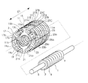
以下、図面を参照して本発明を実施するための最良の形態について説明する。図1は、本発明の一実施の形態のシリンダ型リニアモータの要部の分解斜視図であり、図2は図1のモータの後述する電機子3の分解斜視図である。図1に示すように、本例のシリンダ型リニアモータは、永久磁石磁極部材1と電機子3とを有している。永久磁石磁極部材1は、細長い円柱状の直動軸5と、直動軸5に固定された細長い筒状の永久磁石取付部7と、N極とS極とが交互に直線状に並ぶように、永久磁石取付部7の外周に取り付けられた環状の複数の永久磁石9とを有しており、本例では可動子を構成している。永久磁石磁極部材1は、後述する電機子3の複数の環状の磁極部11b内に配置されており、電機子3に対して直動軸5の長手方向に往復動する。
The best mode for carrying out the present invention will be described below with reference to the drawings. FIG. 1 is an exploded perspective view of a main part of a cylinder type linear motor according to an embodiment of the present invention, and FIG. 2 is an exploded perspective view of an
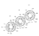
電機子3は、電機子コア11と6つの励磁巻線13A〜13Fとを有しており、本例では固定子を構成している。なお、理解を容易にするため、図1においては励磁巻線13A〜13Fの図示を省略しており、図2においては励磁巻線13A〜13Fを簡略化した形で描いている。電機子コア11は、第1〜第6の分割コア15,17,19,21,23,25が永久磁石磁極部材1の周方向に順番に組み合わされて構成されている。図2(A)〜(C)に示すように、第1〜第6の分割コア15〜25のそれぞれは、ヨーク構成部15a〜25aと、1つの励磁巻線(13A〜13F)が巻装される巻線巻装部15b〜25bと、n個(本例では3個)の分割磁極部15c〜25cとを備えている。ヨーク構成部15a〜25aは、いずれも円弧状を呈しており、これらのヨーク構成部15a〜25aが組み合わされて電機子コア11の円筒状のヨーク11a(図1)が構成される。本例では、ヨーク構成部15a〜25aのそれぞれに隣接するヨーク構成部に対して突出する凸部11cと開口する凹部11dとを形成し、隣接するヨーク構成部の凸部11cと凹部11dとを嵌合して、ヨーク構成部15a〜25aが組み合わされる。分割磁極部15c〜25cは、励磁巻線13A〜13Cにより同じ極性に励磁されるn個(本例では3個)の環状の磁極部11b(図1)の半部をそれぞれ構成している。本例では、第1及び第4の分割コア15,21の巻線巻装部15b,21bにU相の励磁巻線13A,13Dを巻装し、第2及び第5の分割コア17,23の巻線巻装部17b,23bにV相の励磁巻線13B,13Eを巻装し、第3及び第6の分割コア19,25の巻線巻装部19b,25bにW相の励磁巻線13C,13Fを巻装した。これにより、分割磁極部15c,21cは、U相の励磁巻線13A,13Dにより同じ極性に励磁され、分割磁極部17c,23cは、V相の励磁巻線13B,13Eにより同じ極性に励磁され、分割磁極部19c,25cは、W相の励磁巻線13C,13Fにより同じ極性に励磁される。
The
更に、第1〜第6の分割コア15〜25のそれぞれは、第1の種類の複数枚の鋼板が積層されて構成される2n個(本例では6個)の第1の分割コア部分ユニット15A〜25Aと、第2の種類の複数枚の鋼板が積層されて構成されるn個(本例では3個)の第2の分割コア部分ユニット15B〜25Bとが積層されて構成されている。本例では、第1の分割コア部分ユニット15A〜25Aのそれぞれにより、ヨーク構成部15a〜25a及び巻線巻装部15b〜25bの一部のそれぞれが構成されている。また、第2の分割コア部分ユニット15B〜25Bのそれぞれにより、ヨーク構成部15a〜25a及び巻線巻装部15b〜25bの他の一部並びに1つの分割磁極部(15c〜25c)のそれぞれが構成されている。これにより、電機子コア11は、図3(A)〜(C)に示すような3種類の第1〜第3のコア構成体27A〜27Cが永久磁石磁極部材1の往復動方向に順次に積層されて構成されることになる。また、図2(A)に示すように、第1の分割コア15の3個の分割磁極部15cと第4の分割コア21の3個の分割磁極部21cとが組み合わされて3個の磁極部からなる第1の磁極部グループ29が構成され、図2(B)に示すように、第2の分割コア17の3個の分割磁極部17cと第5の分割コア23の3個の分割磁極部23cとが組み合わされて3個の磁極部からなる第2の磁極部グループ31が構成され、図2(C)に示すように、第3の分割コア19の3個の分割磁極部19cと第6の分割コア25の3個の分割磁極部25cとが組み合わされて3個の磁極部からなる第3の磁極部グループ33が構成されている。本例では、分割磁極部15c〜25cは半円の円弧部を有する形状を有しており、円弧部の両端部に対向する分割磁極部に対して突出する凸部11eと開口する凹部11fとをそれぞれ形成し、対向する分割磁極部の凸部11eと凹部11fとを嵌合して、分割磁極部15c〜25cが組み合わされている。
Further, each of the first to sixth divided
各磁極部グループの構成をより具体的に説明すると、図2(A)に示す第1及び第4の分割コア15,21においてそれぞれ用いられる6個の第1の分割コア部分ユニット(15A,21A)及び3個の第2の分割コア部分ユニット(15B,21B)は、第1の分割コア15と第4の分割コア21とが組み合わされて第1の磁極部グループ29が完成した状態で、一端側に第2の分割コア部分ユニット(15B,21B)の一つが位置し且つ他端側に第1の分割コア部分ユニット(15A,21A)の1つが位置し、第1の分割コア部分ユニット(15A,21A)の内側に、図2(B)に示す第2の磁極部グループ31の1つの磁極部(17c,23c)と図2(C)に示す第3の磁極部グループ33の1つの磁極部(19c,25c)とが第1の分割コア部分ユニット29と接触しない状態で位置するように定められている。また、図2(B)に示す第2及び第5の分割コア17,23において用いられる6個の第1の分割コア部分ユニット(17A,23A)及び3個の第2の分割コア部分ユニット(17B,23B)は、第2の分割コア17と第5の分割コア23とが組み合わされて第2の磁極部グループ31が完成した状態で、両端にそれぞれ1個の第1の分割コア部分ユニット(17A,23A)が位置し、両端に位置する一方の第1の分割コア部分ユニット17Aの内側に第1の磁極部グループ29に含まれる1つの磁極部(15c,21c)が一方の第1の分割コア部分ユニット(17A,23A)と接触しない状態で位置し、両端に位置する他方の第1の分割コア部分ユニット(17A,23A)の内側に図2(C)に示す第3の磁極部グループ33に含まれる1つの磁極部(19c,25c)が他方の第1の分割コア部分ユニット(17A,23A)と接触しない状態で位置し、他の第1の分割コア部分ユニット(17A,23A)の内側に、図2(A)に示す第1の磁極部グループ29の1つの磁極部(15c,21c)と図2(C)に示す第3の磁極部グループ33の1つの磁極部(19c,25c)とが第1の分割コア部分ユニット(17A,23A)と接触しない状態で位置するように定められている。また、図2(C)に示す第3及び第6の分割コア19,25において用いられる6個の第1の分割コア部分ユニット19A,25A及び3個の第2の分割コア部分ユニット19B,25Bは、第3の分割コア19と第6の分割コア25とが組み合わされて第3の磁極部グループ33が完成した状態で、一端側に第1の分割コア部分ユニット(19A,25A)の1つのが位置し他端側に第2の分割コア部分ユニット(19B,25B)の一つが位置し、第1の分割コア部分ユニット(19A,25A)の内側に、図2(A)に示す第1の磁極部グループ29の1つの磁極部(15c,21c)と図2(B)に示す第2の磁極部グループ31の1つの磁極部(17c,23c)とが第1の分割コア部分ユニット(19A,25A)と接触しない状態で位置するように定められている。本例では、第1の磁極部グループ29の3個の磁極部(15c,21c)、第2の磁極部グループ31の3個の磁極部(17c,23c)及び第3の磁極部グループ33の3個の磁極部(19c,25c)は、互いに非接触状態になるように各分割コアの第1の分割コアユニットの厚みを定めることにより、前述の各磁極部グループの磁極部の非接触化を図っている。具体的には、積層鋼板の枚数を調整して、第2の分割コア部分ユニット(15B等)を第1の分割コア部分ユニット(15A等)の厚みより薄くしている。
The configuration of each magnetic pole part group will be described more specifically. Six first divided core partial units (15A, 21A) used in the first and fourth divided
本例の電機子3は、次のようにして製造した。まず、図2(A)〜(C)に示すように、第1の分割コア部分ユニット(15A等)と第2の分割コア部分ユニット(15B等)を組み合わせて分割コア(15等)を作ってから、巻線(13A等)を各分割コア(15等)に巻装する。次に、分割コア(15〜25)を相互に組み合わせる。このような組み合わせは、例えば、第1の分割コア15の隣接する磁極部15cと磁極部15cとの間の空隙に第2の分割コア17の磁極部17cを挿入することにより行う。そして、分割コア(15〜25)のヨーク構成部(15a〜25a)の凸部11cと凹部11dとをそれぞれ嵌合し、分割磁極部(15c〜25c)の凸部11eと凹部11fとをそれぞれ嵌合して、電機子3の製造を完了した。
The
本例のシリンダ型リニアモータでは、電機子コア11を、永久磁石磁極部材1の周方向に順番に組み合わされる第1〜第6の分割コア15〜25から構成し、励磁巻線13A,13Dが巻装された第1及び第4の分割コア15,21の巻線巻装部15b,21bに接続されたn個の環状の磁極部(15c,21c)と、励磁巻線13B,13Eが巻装された第2及び第5の分割コア17,23の巻線巻装部17b,23bに接続されたn個の環状の磁極部(17c,23c)と、励磁巻線13C,13Fが巻装された第3及び第6の分割コア19,25の巻線巻装部19b,25bに接続されたn個の環状の磁極部(19c,25c)とを交互に順次並べて配置して、電機子コアの3n個の環状の磁極部11bを構成している。このため、環状の磁極部を形成した状態で、永久磁石磁極部材1の周方向と直交する方向D1(図1)に励磁巻線13A〜13Fを巻装でき、励磁巻線13A〜13Fの配置スペースを永久磁石磁極部材1の周方向と直交する方向D1に延ばすことができる。そのため、3n個の環状の磁極部11bを設けても、第1〜第6の分割コア15〜25の横断面の形状(永久磁石磁極部材の横断面と同じ方向に切断した形状)を同一形状にでき、複数枚の鋼板を積層して第1〜第6の分割コア15〜25を構成することが可能になった。その結果、電機子コア11の製造コストを低くし、鉄損を少なくして、しかも、電機子コア11の設計の自由度を高くすることができる。また、分割コア15〜25を組み合わせる前の段階で分割コア15〜25の巻線巻装部15b〜25bに励磁巻線13A〜13Fを巻装でき、励磁巻線13A〜13Fを容易に巻装することができる。
In the cylinder type linear motor of this example, the
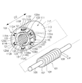
図4は、本発明の他の実施の形態のシリンダ型リニアモータの要部の分解斜視図である。図4に示すように、本例のシリンダ型リニアモータは、永久磁石磁極部材101と電機子103とを有している。永久磁石磁極部材101は、細長い円柱状の直動軸105と、直動軸105に固定された細長い筒状の永久磁石取付部107と、N極とS極とが交互に直線状に並ぶように、永久磁石取付部107の外周に取り付けられた環状の複数の永久磁石109とを有しており、可動子を構成している。永久磁石磁極部材101は、後述する電機子103の磁極部構成体115内に配置されており、電機子103に対して直動軸105の長手方向に往復動する。
FIG. 4 is an exploded perspective view of a main part of a cylinder type linear motor according to another embodiment of the present invention. As shown in FIG. 4, the cylinder type linear motor of this example includes a permanent magnet
電機子103は、電機子コア111と6つの励磁巻線112A〜112Fとを有しており、固定子を構成されている。なお、理解を容易にするため、励磁巻線112A〜112Fは簡略化して描いている。電機子コア111は、コア本体113とコア本体113の内部に配置された筒状の磁極部構成体115とを有している。コア本体113は、円筒状のヨーク117と円筒状のヨーク117の内側に周方向に等しい間隔をあけて配置された第1〜第6の突極部119A〜119Fとを有しており、複数枚の鋼板が積層されて構成されている。第1〜第6の突極部119A〜119Fは、第1〜第6の励磁巻線112A〜112Fの1つが巻装される巻線巻装部121と、巻線巻装部121の端部に設けられた磁極接続部123とをそれぞれ有している。磁極接続部123は、永久磁石磁極部材101の周方向に延びており、永久磁石磁極部材101と対向する側(突極部の極面)には、永久磁石磁極部材101の軸線方向に延びる溝状の嵌合用凹部123aが形成されている。
The
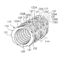
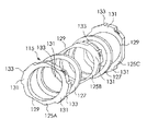
磁極部構成体115は、図5及び図6に示すように、3n個(本例では9個)の環状の磁極部125A〜125Cが8個の円環状の合成樹脂からなるスペーサ部材127を介して順次に積層されて構成されている。なお、図5は磁極部構成体115の斜視図であり、図6は図5は磁極部構成体115の一部を分解した斜視図である。図6に示すように、磁極部125A〜125Cは、いずれも環状部129と円弧状の一対の突状部131と一対の嵌合用凸部133とを備えた同じ構造を有しており、複数枚の環状の鋼板が積層されて構成されている。環状部129は、磁極部構成体115がコア本体113内に配置された状態で、コア本体113の磁極接続部123と接触しないように6個の磁極接続部123に囲まれた内部に配置されている。一対の突状部131は、環状部129を間にして環状部129の径方向に対向するように位置しており、その外面がヨーク117の径方向に対向する一対の突極部の磁極接続部123の内面と接触できる寸法及び形状を有している。一対の嵌合用凸部133は、一対の突状部131の外周中央から磁極部125A〜125Cの厚み方向に延びてコア本体113側にそれぞれ突出しており、該一対の突極部の磁極接続部123の嵌合用凹部123aにそれぞれ嵌合可能な寸法及び形状を有している。
As shown in FIGS. 5 and 6, the magnetic pole
3n個(本例では9個)の磁極部125A〜125Cの内、2つ置きに配置されるn個(本例では3個)の磁極部125Aは、一対の突状部131が第1及び第4の突極部119A,119Dの磁極接続部123の内面と接触し、一対の嵌合用凸部133が第1及び第4の突極部119A,119Dの嵌合用凹部123aに嵌合されるように配置されている。これにより、n個の磁極部125Aが第1及び第4の突極部119A,119Dに結合されて同じ極性に励磁される第1の磁極部グループが構成される。また、9個の磁極部125A〜125Cの内、2つ置きに配置される他の3個の磁極部125Bは、一対の突状部131が第2及び第5の突極部119B,119Eの磁極接続部123の内面と接触し、一対の嵌合用凸部133が第2及び第5の突極部119B,119Eの嵌合用凹部123aに嵌合されるように配置されている。これにより、他のn個の磁極部125Bが第2及び第5の突極部119B,119Eに結合されて同じ極性に励磁される第2の磁極部グループが構成される。また、9個の磁極部125A〜125Cの内、2つ置きに配置される残りの3個の磁極部125Cは、一対の突状部131が第3及び第6の突極部119C,119Fの磁極接続部123の内面と接触し、一対の嵌合用凸部133が第3及び第6の突極部119C,119Fの嵌合用凹部123aに嵌合されるように配置されている。これにより、残りのn個の磁極部125Cが第3及び第6の突極部119C,119Fに結合されて同じ極性に励磁される第3の磁極部グループが構成される。本例では、第1及び第4の突極部119A,119Dの巻線巻装部121にU相の励磁巻線112A,112Dを巻装し、第2及び第5の突極部119B,119Eの巻線巻装部121にV相の励磁巻線112B,112Eを巻装し、第3及び第6の突極部119C,119Fの巻線巻装部121にW相の励磁巻線112C,112Fを巻装した。これにより、n個の磁極部125Aは、U相の励磁巻線により同じ極性に励磁され、n個の磁極部125Bは、V相の励磁巻線により同じ極性に励磁され、n個の磁極部125Cは、W相の励磁巻線により同じ極性に励磁される。また、第1〜第3の磁極部グループは、永久磁石磁極部材101の磁極ピッチをτp(図4)としたときに、第1〜第3の磁極部グループをそれぞれ構成するn個の磁極部間の間隔τm(図5)は、τm=2τp+τp/3nになるように構成されている。
Among the 3n (9 in this example)
本例のシリンダ型リニアモータでは、3n個の環状の磁極部125A〜125Cからなる磁極部構成体115と、内側に第1〜第6の励磁巻線112A〜112Fがそれぞれ巻装される第1〜第6の突極部119A〜119Fが周方向に等しい間隔をあけて配置されたコア本体113とから電機子コア111が構成され、3n個中のn個の磁極部125Aが、第1及び第4の突極部119A,119Dに結合されて同じ極性に励磁され、3n個中の他のn個の磁極部125Bが、第2及び第5の突極部119B,119Eに結合されて同じ極性に励磁され、3n個中の残りのn個の磁極部125Cが、第3及び第6の突極部119C,119Fに結合されて同じ極性に励磁されている。このため、本発明では、環状の磁極部125A〜125Cを形成した状態で、永久磁石磁極部材101の周方向と直交する方向D2(図4)に延びる第1〜第6の突極部119A〜119Fに励磁巻線112A〜112Fを巻装でき、励磁巻線112A〜112Fの配置スペースを永久磁石磁極部材101の周方向と直交する方向D2に延ばすことができる。そのため、3n個の環状の磁極部125A〜125Cを設けても、コア本体113及び3n個の磁極部125A〜125Cの横断面の形状(永久磁石磁極部材101の横断面と同じ方向に切断した形状)を同一形状にでき、複数枚の鋼板を積層してコア本体113及び磁極部125A〜125Cを構成することができる。その結果、電機子コアの製造コストを低くし、鉄損を少なくして、しかも、電機子コアの設計の自由度を高くすることができる。
In the cylinder type linear motor of this example, a magnetic
1,101 永久磁石磁極部材(可動子)
3,103 電機子(固定子)
11,111 電機子コア
13A〜13F 励磁巻線
15〜25 第1〜第6の分割コア
15a〜25a ヨーク構成部
15b〜25b 巻線巻装部
15c〜25c 分割磁極部
15A〜25A 第1の分割コア部分ユニット
15B〜25B 第2の分割コア部分ユニット
29 第1の磁極部グループ
31 第2の磁極部グループ
33 第3の磁極部グループ
112A〜112F 励磁巻線
113 コア本体
115 磁極部構成体
119A〜119F 第1〜第6の突極部
123a 嵌合用凹部
125A〜125C 磁極部
127 スペーサ部材
133 嵌合用凸部
1,101 Permanent magnet pole member (mover)
3,103 Armature (stator)
11,111
Claims (9)
前記N極と前記S極とが交互に並ぶ方向に並び且つ前記永久磁石磁極部材の周囲をそれぞれ囲む3n個(nは自然数)の環状の磁極部を備えた電機子コアと、前記電機子コアに装着されて隣り合う二つの前記環状の磁極部が異なる極性に励磁されるように前記3n個の磁極部をそれぞれ励磁する複数の励磁巻線とを有する電機子とを備え、
前記永久磁石磁極部材及び前記電機子の一方が可動子となり他方が固定子となるシリンダ型リニアモータであって、
前記電機子コアは、前記永久磁石磁極部材の周方向に順番に組み合わされる第1〜第6の分割コアから構成され、
前記第1〜第6の分割コアは、前記電機子コアの環状のヨークの一部を構成するヨーク構成部と、1つの前記励磁巻線が巻装される巻線巻装部と、前記励磁巻線により同じ極性に励磁されるn個の前記環状の磁極部の半部を構成するn個の分割磁極部とをそれぞれ備えており、
前記第1〜第6の分割コアは、それぞれ第1の種類の複数枚の鋼板が積層されて構成され前記ヨーク構成部及び前記巻線巻装部の一部を構成する2n個の第1の分割コア部分ユニットと、第2の種類の複数枚の鋼板が積層されて構成されて前記ヨーク構成部及び前記巻線巻装部の一部並びに1つの前記分割磁極部を構成するn個の第2の分割コア部分ユニットとが積層されて構成され、
前記第1の分割コアの前記n個の分割磁極部と前記第4の分割コアの前記n個の分割磁極部とが組み合わされてn個の前記磁極部からなる第1の磁極部グループが構成され、
前記第2の分割コアの前記n個の分割磁極部と前記第5の分割コアの前記n個の分割磁極部とが組み合わされてn個の前記磁極部からなる第2の磁極部グループが構成され、
前記第3の分割コアの前記n個の分割磁極部と前記第6の分割コアの前記n個の分割磁極部とが組み合わされてn個の前記磁極部からなる第3の磁極部グループが構成され、
前記第1及び第4の分割コアにおいて用いられる2n個の前記第1の分割コア部分ユニット及びn個の前記第2の分割コア部分ユニットは、それぞれ前記第1及び第4の分割コアが組み合わされて前記第1の磁極部グループが完成した状態で、一端側に前記第2の分割コア部分ユニットの一つが位置し且つ他端側に前記第1の分割コア部分ユニットの1つが位置し、前記第1の分割コア部分ユニットの内側に、前記第2の磁極部グループの1つの前記磁極部と前記第3の磁極部グループの1つの前記磁極部とが前記第1の分割コア部分ユニットと接触しない状態で位置するように定められており、
前記第2及び第5の分割コアにおいて用いられる2n個の前記第1の分割コア部分ユニット及びn個の前記第2の分割コア部分ユニットは、それぞれ前記第2及び第5の分割コアが組み合わされて前記第2の磁極部グループが完成した状態で、両端にそれぞれ1個の前記第1の分割コア部分ユニットが位置し、前記両端に位置する一方の前記第1の分割コア部分ユニットの内側に前記第1の磁極部グループに含まれる1つの前記磁極部が前記一方の第1の分割コア部分ユニットと接触しない状態で位置し、前記両端に位置する他方の前記第1の分割コア部分ユニットの内側に前記第3の磁極部グループに含まれる1つの前記磁極部が前記他方の第1の分割コア部分ユニットと接触しない状態で位置し、他の前記第1の分割コア部分ユニットの内側に、前記第1の磁極部グループの1つの前記磁極部と前記第3の磁極部グループの1つの前記磁極部とが前記第1の分割コア部分ユニットと接触しない状態で位置するように定められており、
前記第3及び第6の分割コアにおいて用いられる2n個の前記第1の分割コア部分ユニット及びn個の前記第2の分割コア部分ユニットは、それぞれ前記第3及び第6の分割コアが組み合わされて前記第3の磁極部グループが完成した状態で、一端側に第1の分割コア部分ユニットの1つが位置し他端側に前記第2の分割コア部分ユニットの一つが位置し、前記第1の分割コア部分ユニットの内側に、前記第1の磁極部グループの1つの前記磁極部と前記第2の磁極部グループの1つの前記磁極部とが前記第1の分割コア部分ユニットと接触しない状態で位置するように定められていることを特徴とすることを特徴とするシリンダ型リニアモータ。 A permanent magnet magnetic pole member composed of N poles and S poles composed of permanent magnets arranged in a straight line alternately;
An armature core having 3n (n is a natural number) annular magnetic pole portions arranged in a direction in which the N pole and the S pole are alternately arranged and surrounding each of the permanent magnet magnetic pole members, and the armature core An armature having a plurality of exciting windings that respectively excite the 3n magnetic pole portions so that the two adjacent annular magnetic pole portions that are attached to each other are excited with different polarities,
A cylinder type linear motor in which one of the permanent magnet magnetic pole member and the armature is a mover and the other is a stator,
The armature core is composed of first to sixth divided cores combined in order in the circumferential direction of the permanent magnet magnetic pole member,
The first to sixth divided cores include a yoke component that constitutes a part of an annular yoke of the armature core, a winding winding portion around which the one excitation winding is wound, and the excitation N divided magnetic pole parts constituting half of the annular magnetic pole parts excited to the same polarity by windings, respectively.
Each of the first to sixth split cores is formed by laminating a plurality of first-type steel plates, and 2n first first cores constituting a part of the yoke constituent part and the winding winding part. The divided core portion unit and a plurality of second-type steel plates are laminated to constitute the yoke component, a part of the winding winding portion, and the n number of divided magnetic pole portions. 2 divided core partial units are laminated,
The n divided magnetic pole portions of the first divided core and the n divided magnetic pole portions of the fourth divided core are combined to form a first magnetic pole portion group consisting of n magnetic pole portions. And
The n divided magnetic pole portions of the second divided core and the n divided magnetic pole portions of the fifth divided core are combined to form a second magnetic pole portion group including n magnetic pole portions. And
The n divided magnetic pole portions of the third divided core and the n divided magnetic pole portions of the sixth divided core are combined to form a third magnetic pole portion group composed of n magnetic pole portions. And
The 2n first divided core partial units and n second divided core partial units used in the first and fourth divided cores are combined with the first and fourth divided cores, respectively. In a state where the first magnetic pole part group is completed, one of the second divided core partial units is located on one end side and one of the first divided core partial units is located on the other end side, One magnetic pole part of the second magnetic pole part group and one magnetic pole part of the third magnetic pole part group are in contact with the first split core partial unit inside the first split core partial unit. It is determined to be located in a state that does not
In the 2n first divided core partial units and n second divided core partial units used in the second and fifth divided cores, the second and fifth divided cores are combined, respectively. In a state where the second magnetic pole part group is completed, one first divided core part unit is located at each end, and inside one of the first divided core part units located at both ends. One of the magnetic pole portions included in the first magnetic pole portion group is located in a state where it is not in contact with the first divided core partial unit, and the other of the first divided core partial units located at both ends of the first magnetic pole portion group. One of the magnetic pole portions included in the third magnetic pole portion group is located on the inner side so as not to contact the other first divided core portion unit, and the other of the first divided core portion units The one magnetic pole part of the first magnetic pole part group and the one magnetic pole part of the third magnetic pole part group are positioned so as not to be in contact with the first split core partial unit. And
The 2n first divided core partial units and n second divided core partial units used in the third and sixth divided cores are combined with the third and sixth divided cores, respectively. In a state where the third magnetic pole portion group is completed, one of the first divided core partial units is located on one end side, and one of the second divided core partial units is located on the other end side, A state in which one magnetic pole part of the first magnetic pole part group and one magnetic pole part of the second magnetic pole part group are not in contact with the first split core partial unit inside the split core partial unit A cylinder type linear motor characterized in that it is determined to be positioned at
前記N極と前記S極とが交互に並ぶ方向に並び且つ前記永久磁石磁極部材の周囲をそれぞれ囲む3n個(nは自然数)の環状の磁極部を備えた電機子コアと、前記電機子コアに装着されて隣り合う二つの前記環状の磁極部が異なる極性に励磁されるように前記3n個の磁極部をそれぞれ励磁する複数の励磁巻線とを有する電機子とを備え、
前記永久磁石磁極部材及び前記電機子の一方が可動子となり他方が固定子となるシリンダ型リニアモータであって、
前記電機子コアは、
複数枚の環状の鋼板が積層されて構成された前記3n個の環状の磁極部からなる磁極部構成体と、
複数枚の鋼板が積層されて構成され、内側に第1〜第6の励磁巻線がそれぞれ巻装される第1〜第6の突極部が周方向に等しい間隔をあけて配置された構造を有するコア本体とを備えており、
前記3n個の環状の磁極部に含まれるn個の前記磁極部が、前記第1及び第4の突極部に結合されて同じ極性に励磁される第1の磁極部グループを構成し、
前記3n個の環状の磁極部に含まれる他のn個の前記磁極部が、前記第2及び第5の突極部に結合されて同じ極性に励磁される第2の磁極部グループを構成し、
前記3n個の環状の磁極部に含まれる残りのn個の前記磁極部が、前記第3及び第6の突極部に結合されて同じ極性に励磁される第3の磁極部グループを構成するように前記コア本体の内側に前記3n個の環状の磁極部が配置されていることを特徴とするシリンダ型リニアモータ。 A permanent magnet magnetic pole member composed of N poles and S poles composed of permanent magnets arranged in a straight line alternately;
An armature core having 3n (n is a natural number) annular magnetic pole portions arranged in a direction in which the N pole and the S pole are alternately arranged and surrounding each of the permanent magnet magnetic pole members, and the armature core An armature having a plurality of exciting windings that respectively excite the 3n magnetic pole portions so that the two adjacent annular magnetic pole portions that are attached to each other are excited with different polarities,
A cylinder type linear motor in which one of the permanent magnet magnetic pole member and the armature is a mover and the other is a stator,
The armature core is
A magnetic pole part structure comprising the 3n annular magnetic pole parts formed by laminating a plurality of annular steel plates; and
A structure in which a plurality of steel plates are laminated, and first to sixth salient pole portions on which first to sixth exciting windings are respectively wound are arranged at equal intervals in the circumferential direction. A core body having
The n magnetic pole portions included in the 3n annular magnetic pole portions are coupled to the first and fourth salient pole portions to form a first magnetic pole portion group that is excited to the same polarity,
The other n number of the magnetic pole portions included in the 3n annular magnetic pole portions are coupled to the second and fifth salient pole portions to form a second magnetic pole portion group that is excited to the same polarity. ,
The remaining n magnetic pole portions included in the 3n annular magnetic pole portions are coupled to the third and sixth salient pole portions to form a third magnetic pole portion group that is excited to the same polarity. Thus, the cylinder type linear motor is characterized in that the 3n annular magnetic pole portions are arranged inside the core body.
Priority Applications (1)
| Application Number | Priority Date | Filing Date | Title |
|---|---|---|---|
| JP2004106602A JP4551684B2 (en) | 2004-03-31 | 2004-03-31 | Cylinder type linear motor |
Applications Claiming Priority (1)
| Application Number | Priority Date | Filing Date | Title |
|---|---|---|---|
| JP2004106602A JP4551684B2 (en) | 2004-03-31 | 2004-03-31 | Cylinder type linear motor |
Publications (2)
| Publication Number | Publication Date |
|---|---|
| JP2005295675A true JP2005295675A (en) | 2005-10-20 |
| JP4551684B2 JP4551684B2 (en) | 2010-09-29 |
Family
ID=35328003
Family Applications (1)
| Application Number | Title | Priority Date | Filing Date |
|---|---|---|---|
| JP2004106602A Expired - Fee Related JP4551684B2 (en) | 2004-03-31 | 2004-03-31 | Cylinder type linear motor |
Country Status (1)
| Country | Link |
|---|---|
| JP (1) | JP4551684B2 (en) |
Cited By (4)
| Publication number | Priority date | Publication date | Assignee | Title |
|---|---|---|---|---|
| JP2007181370A (en) * | 2005-12-28 | 2007-07-12 | Shinko Electric Co Ltd | Linear motor and method of manufacturing stator included therein |
| JP2010057338A (en) * | 2008-08-29 | 2010-03-11 | Hitachi Metals Ltd | Mover, armature, and actuator |
| JP2011120457A (en) * | 2009-11-09 | 2011-06-16 | Sanyo Denki Co Ltd | Electrical machine apparatus |
| US8723376B2 (en) | 2009-01-23 | 2014-05-13 | Hitachi Metals, Ltd. | Mover and linear motor |
Families Citing this family (1)
| Publication number | Priority date | Publication date | Assignee | Title |
|---|---|---|---|---|
| CN105048659A (en) * | 2015-09-10 | 2015-11-11 | 湘潭电机股份有限公司 | Stator iron core for motor and motor |
Citations (3)
| Publication number | Priority date | Publication date | Assignee | Title |
|---|---|---|---|---|
| JPS4745131B1 (en) * | 1970-05-12 | 1972-11-14 | ||
| JPH07336992A (en) * | 1994-06-06 | 1995-12-22 | Oriental Motor Co Ltd | Linear pulse motor |
| JP2001286122A (en) * | 2000-03-31 | 2001-10-12 | Sanyo Denki Co Ltd | Cylinder-type linear synchronous motor |
-
2004
- 2004-03-31 JP JP2004106602A patent/JP4551684B2/en not_active Expired - Fee Related
Patent Citations (3)
| Publication number | Priority date | Publication date | Assignee | Title |
|---|---|---|---|---|
| JPS4745131B1 (en) * | 1970-05-12 | 1972-11-14 | ||
| JPH07336992A (en) * | 1994-06-06 | 1995-12-22 | Oriental Motor Co Ltd | Linear pulse motor |
| JP2001286122A (en) * | 2000-03-31 | 2001-10-12 | Sanyo Denki Co Ltd | Cylinder-type linear synchronous motor |
Cited By (5)
| Publication number | Priority date | Publication date | Assignee | Title |
|---|---|---|---|---|
| JP2007181370A (en) * | 2005-12-28 | 2007-07-12 | Shinko Electric Co Ltd | Linear motor and method of manufacturing stator included therein |
| JP2010057338A (en) * | 2008-08-29 | 2010-03-11 | Hitachi Metals Ltd | Mover, armature, and actuator |
| US8723376B2 (en) | 2009-01-23 | 2014-05-13 | Hitachi Metals, Ltd. | Mover and linear motor |
| US9071124B2 (en) | 2009-01-23 | 2015-06-30 | Hitachi Metals, Ltd. | Mover and linear motor |
| JP2011120457A (en) * | 2009-11-09 | 2011-06-16 | Sanyo Denki Co Ltd | Electrical machine apparatus |
Also Published As
| Publication number | Publication date |
|---|---|
| JP4551684B2 (en) | 2010-09-29 |
Similar Documents
| Publication | Publication Date | Title |
|---|---|---|
| CN1158740C (en) | Stator structure of reciprocating electric machine | |
| US8575810B2 (en) | Motor | |
| US7528519B2 (en) | Permanent magnet rotary motor | |
| JP5382156B2 (en) | Rotating electric machine | |
| JP2011024324A (en) | Permanent-magnet type synchronous motor | |
| CN104011972A (en) | Hybrid excitation-type rotating machine | |
| JP4984347B2 (en) | Electric motor | |
| JP6065568B2 (en) | Magnetizer | |
| JP2004215442A (en) | Permanent magnet embedded synchronous motor | |
| JP3220537B2 (en) | Linear pulse motor | |
| JP5041415B2 (en) | Axial gap type motor | |
| JP2007143335A (en) | Field element and motor | |
| JP2005151785A (en) | Synchronous generator having annular armature coil | |
| EP1341288B1 (en) | Electric rotary machine | |
| JP3867557B2 (en) | motor | |
| JP4551684B2 (en) | Cylinder type linear motor | |
| JP7259798B2 (en) | axial gap motor | |
| JP2010068548A (en) | Motor | |
| JP2011103716A (en) | Motor | |
| JP2019198220A (en) | Electric motor | |
| JP2011125127A (en) | Motor | |
| JP4497986B2 (en) | Claw pole type three-phase linear motor | |
| JP2009038897A (en) | Axial gap type motor | |
| JP2000236638A (en) | Rotating electric machine stator | |
| JP2010063281A (en) | Permanent magnet type synchronous motor |
Legal Events
| Date | Code | Title | Description |
|---|---|---|---|
| A621 | Written request for application examination |
Free format text: JAPANESE INTERMEDIATE CODE: A621 Effective date: 20070302 |
|
| A977 | Report on retrieval |
Free format text: JAPANESE INTERMEDIATE CODE: A971007 Effective date: 20091217 |
|
| A131 | Notification of reasons for refusal |
Free format text: JAPANESE INTERMEDIATE CODE: A131 Effective date: 20100323 |
|
| A521 | Written amendment |
Free format text: JAPANESE INTERMEDIATE CODE: A523 Effective date: 20100524 |
|
| TRDD | Decision of grant or rejection written | ||
| A01 | Written decision to grant a patent or to grant a registration (utility model) |
Free format text: JAPANESE INTERMEDIATE CODE: A01 Effective date: 20100622 |
|
| A01 | Written decision to grant a patent or to grant a registration (utility model) |
Free format text: JAPANESE INTERMEDIATE CODE: A01 |
|
| A61 | First payment of annual fees (during grant procedure) |
Free format text: JAPANESE INTERMEDIATE CODE: A61 Effective date: 20100712 |
|
| R150 | Certificate of patent or registration of utility model |
Free format text: JAPANESE INTERMEDIATE CODE: R150 |
|
| FPAY | Renewal fee payment (event date is renewal date of database) |
Free format text: PAYMENT UNTIL: 20130716 Year of fee payment: 3 |
|
| R250 | Receipt of annual fees |
Free format text: JAPANESE INTERMEDIATE CODE: R250 |
|
| R250 | Receipt of annual fees |
Free format text: JAPANESE INTERMEDIATE CODE: R250 |
|
| R250 | Receipt of annual fees |
Free format text: JAPANESE INTERMEDIATE CODE: R250 |
|
| R250 | Receipt of annual fees |
Free format text: JAPANESE INTERMEDIATE CODE: R250 |
|
| LAPS | Cancellation because of no payment of annual fees |