JP2005295633A - Power supply - Google Patents
Power supply Download PDFInfo
- Publication number
- JP2005295633A JP2005295633A JP2004104504A JP2004104504A JP2005295633A JP 2005295633 A JP2005295633 A JP 2005295633A JP 2004104504 A JP2004104504 A JP 2004104504A JP 2004104504 A JP2004104504 A JP 2004104504A JP 2005295633 A JP2005295633 A JP 2005295633A
- Authority
- JP
- Japan
- Prior art keywords
- generator
- voltage
- determination
- output voltage
- temperature
- Prior art date
- Legal status (The legal status is an assumption and is not a legal conclusion. Google has not performed a legal analysis and makes no representation as to the accuracy of the status listed.)
- Granted
Links
Images
Landscapes
- Control Of Eletrric Generators (AREA)
Abstract
【課題】 半導体スイッチング素子を用いて出力電圧の調整を行う場合に、出力電圧が低下する故障をより精度よく検出することができる電源装置を提供する。
【解決手段】 半導体スイッチング素子21の温度TSWが検出され、温度TSWに応じて補正係数Ktempが算出される((S12)。補正係数Ktempにより、半導体スイッチング素子21の制御信号のデューティ比DUTYが補正され、マップデューティ比DUTYMが算出される。マップデューティ比DUTYM及び発電機回転数NGEに応じて判定電圧VREFが算出され、整流回路11の出力電圧VACGが判定電圧VREFより低いとき、発電機1が故障していると判定される。
【選択図】 図2PROBLEM TO BE SOLVED: To provide a power supply device capable of more accurately detecting a failure in which an output voltage is lowered when an output voltage is adjusted using a semiconductor switching element.
A temperature TSW of a semiconductor switching element 21 is detected, and a correction coefficient Ktemp is calculated according to the temperature TSW ((S12). A duty ratio DUTY of a control signal of the semiconductor switching element 21 is corrected by the correction coefficient Ktemp. When the determination voltage VREF is calculated according to the map duty ratio DUTYM and the generator rotational speed NGE, and the output voltage VACG of the rectifier circuit 11 is lower than the determination voltage VREF, the generator 1 is It is determined that there is a failure.
[Selection] Figure 2
Description
本発明は、内燃機関により駆動される発電機を備える電源装置に関し、特に発電機の故障判定機能を有するものに関する。 The present invention relates to a power supply device including a generator driven by an internal combustion engine, and more particularly to a power supply device having a generator failure determination function.
特許文献1には、内燃機関のより駆動される発電機を備える電源装置が示されている。この電源装置は、発電機の発電電圧が過大に上昇する故障を検出し、警報ランプを点滅させる機能を有する。
内燃機関により駆動される発電機では、内燃機関の回転速度により発電電圧が大きく変化するため、発電機の出力電圧を整流した後に、電圧を所定電圧範囲内に入るように調整するレギュレータ回路が設けられ、レギュレータ回路では通常半導体スイッチング素子が使用される。半導体スイッチング素子は、その温度によって特性が変化し、発電機の出力電圧(具体的には整流後の直流電圧)に影響を及ぼす。 A generator driven by an internal combustion engine has a regulator circuit that adjusts the voltage to fall within a predetermined voltage range after rectifying the output voltage of the generator because the generated voltage varies greatly depending on the rotational speed of the internal combustion engine. In the regulator circuit, a semiconductor switching element is usually used. The characteristics of the semiconductor switching element change depending on its temperature, and affect the output voltage of the generator (specifically, the DC voltage after rectification).
上記従来の電源装置では、レギュレータ回路の半導体スイッチング素子の温度特性が考慮されていないため、故障判定の精度の点で改善の余地があった。
本発明はこの点に着目してなされたものであり、半導体スイッチング素子を用いて出力電圧の調整を行う場合に、出力電圧が不足する故障をより精度よく検出することができる電源装置を提供することを目的とする。
In the above conventional power supply device, there is room for improvement in terms of the accuracy of failure determination because the temperature characteristics of the semiconductor switching element of the regulator circuit are not taken into consideration.
The present invention has been made paying attention to this point, and provides a power supply device that can detect a failure in which the output voltage is insufficient when the output voltage is adjusted using a semiconductor switching element. For the purpose.
上記目的を達成するため請求項1に記載の発明は、内燃機関(2)により駆動される発電機(1)と、該発電機(1)の出力電圧を整流する整流手段(11)と、該整流手段(11)の出力に接続された半導体スイッチング素子(21)をデューティ制御することにより、出力電圧が所定電圧範囲内となるように制御する電圧制御手段(12)とを備える電源装置において、前記半導体スイッチング素子(21)の温度(TSW)を検出する温度検出手段(14)と、該温度検出手段(14)により検出される温度(TSW)に応じて、前記デューティ制御のデューティ比(DUTY)を補正する補正手段と、前記発電機の回転速度(NGE)を検出する回転速度検出手段と、該補正手段により補正されたデューティ比(DUTYM)及び前記発電機の回転速度(NGE)に応じて判定電圧(VREF)を算出する判定電圧算出手段と、前記整流手段(11)の出力電圧(VACG)が前記判定電圧(VREF)より低いとき、前記発電機(1)が故障していると判定する故障判定手段とを備えることを特徴とする。
In order to achieve the above object, the invention described in
また請求項2に記載の発明は、内燃機関(2)により駆動される発電機(1)と、該発電機(1)の出力電圧を整流する整流手段(11)と、該整流手段(11)の出力に接続された半導体スイッチング素子(21)をデューティ制御することにより、出力電圧が所定電圧範囲内となるように制御する電圧制御手段(12)とを備える電源装置において、前記発電機(1)の回転速度(NGE)を検出する回転速度検出手段と、前記発電機の回転速度(NGE)及び前記デューティ制御のデューティ比(DUTY)に応じて、前記発電機の故障判定に用いる判定電圧(VREF)を算出する判定電圧算出手段と、前記半導体スイッチング素子の温度(TSW)を検出する温度検出手段(14)と、該温度検出手段(14)により検出される温度(TSW)に応じて、前記判定電圧(VREF)を補正する補正手段と、前記整流手段の出力電圧(VACG)が前記補正手段により補正された判定電圧(VREF)より低いとき、前記発電機が故障していると判定する故障判定手段とを備えることを特徴とする。
The invention described in
請求項1に記載の発明によれば、半導体スイッチング素子の温度に応じて、デューティ制御のデューティ比が補正され、補正されたデューティ比及び発電機の回転速度に応じて判定電圧が算出される。そして、整流手段の出力電圧が判定電圧より低いとき、発電機が故障していると判定される。補正されたデューティ比を用いて判定電圧を算出することにより、半導体スイッチ素子の温度に適した判定電圧が得られ、故障判定の精度を向上させることができる。 According to the first aspect of the present invention, the duty ratio of the duty control is corrected according to the temperature of the semiconductor switching element, and the determination voltage is calculated according to the corrected duty ratio and the rotational speed of the generator. Then, when the output voltage of the rectifying means is lower than the determination voltage, it is determined that the generator has failed. By calculating the determination voltage using the corrected duty ratio, a determination voltage suitable for the temperature of the semiconductor switch element can be obtained, and the accuracy of failure determination can be improved.
請求項2に記載の発明によれば、半導体スイッチング素子の温度に応じて、判定電圧が補正され、整流手段の出力電圧が補正された判定電圧より低いとき、発電機が故障していると判定される。したがって、半導体スイッチング素子の温度に応じた適切な判定電圧を用いて故障判定が行われ、故障判定の精度を向上させることができる。 According to the second aspect of the present invention, when the determination voltage is corrected according to the temperature of the semiconductor switching element and the output voltage of the rectifying means is lower than the corrected determination voltage, it is determined that the generator has failed. Is done. Therefore, failure determination is performed using an appropriate determination voltage corresponding to the temperature of the semiconductor switching element, and the accuracy of failure determination can be improved.
以下本発明の実施の形態を図面を参照して説明する。
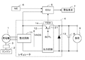
図1は本発明の一実施形態にかかる車両用電源装置及びその周辺回路の構成を示すブロック図である。図1に示す電源装置は、内燃機関(エンジン)2により変速装置3(プーリとベルトとから成る)を介して駆動される発電機1と、発電機1の出力電圧を整流し、電圧を調整するレギュレータ4と、発電機1の故障判定を行う電子制御ユニット(以下「ECU」という)5と、前記機関2の回転数(回転速度)NEを検出する回転数センサ6と、故障が検出されたとき、警告表示を行う警告表示部7とを備えている。電源装置の出力には、バッテリ8及び負荷9が接続されている。負荷9は、本実施形態では、例えば灯火類、イグニッションコイル、空調装置用ファンなどである。
Embodiments of the present invention will be described below with reference to the drawings.
FIG. 1 is a block diagram showing a configuration of a vehicle power supply device and its peripheral circuits according to an embodiment of the present invention. The power supply device shown in FIG. 1 adjusts the voltage by rectifying the
レギュレータ4は、発電機1から出力される三相交流電力を直流電力の変換する整流回路11と、出力電圧が所定電圧範囲内に入るように調整する出力回路12と、保護用のダイオード13とを備えている。出力回路12には、出力電圧調整のための半導体スイッチング素子21が設けられており、半導体スイッチング素子21は、デューティ制御信号SCTLにより、オンオフデューティ制御される。さらにレギュレータ4には、半導体スイッチング素子21の温度(以下「SW素子温度」という)TSWを検出する温度センサ14が設けられている。温度センサ14の検出信号は、ECU5に供給される。
The regulator 4 includes a
ECU5には、整流回路11の出力電圧VACG及びエンジン回転数センサ6により検出されるエンジン回転数NEを示す検出信号が供給される。
ECU5は、出力電圧VACG及びエンジン回転数NEの検出信号などを、デジタル値に変換する入力回路、中央処理装置(CPU)、CPUの演算データやCPUの演算プログラム、演算に必要なテーブル及びマップなどを記憶するメモリ回路、及び警告表示部7などに駆動信号を供給する出力回路を備えている。
The
The
ECU5のCPUは、エンジン回転数NE及び出力電圧VACGに基づいて、出力電圧VACGが低下する故障を判定し、故障が発生しているときには、警告表示部7に警告表示を行うとともに、負荷9による消費電流を減少させる制御を行う。
The CPU of the
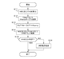
図2は、発電機1の故障判定を行う処理のフローチャートである。この処理は、ECU5のCPUで所定時間(例えば100ミリ秒)毎に実行される。
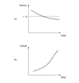
ステップS11では、エンジン回転数NEに変速装置3の変速比(例えば2.5)を乗算して、発電機回転数NGEを算出する。ステップS12では、SW素子温度TSWに応じて図3(a)に示すKtempテーブルを検索し、補正係数Ktempを算出する。同図(b)に示すように、SW素子温度TSWが高くなるほど、半導体スイッチング素子21における電圧降下VDSWが増加することに対応させて、Ktempテーブルは、SW素子温度TSWが高くなるほど、補正係数Ktempが減少するように設定されている。
FIG. 2 is a flowchart of processing for determining a failure of the
In step S11, the engine speed NE is multiplied by the speed ratio (for example, 2.5) of the transmission 3 to calculate the generator speed NGE. In step S12, a Ktemp table shown in FIG. 3A is searched according to the SW element temperature TSW, and a correction coefficient Ktemp is calculated. As shown in FIG. 5B, the Ktemp table is associated with the increase in the voltage drop VDSW in the
ステップS13では、下記式(1)に、デューティ制御信号SCTLのデューティ比DUTY及び補正係数Ktempを適用し、マップデューティ比DUTYMを算出する。
DUTYM=DUTY×Ktemp (1)
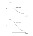
ステップS14では、発電機回転数NGE及びマップデューティ比DUTYMに応じて、VREFマップを検索し、判定電圧VREFを算出する。図4は、VREFマップの設定を説明するための図であり、同図(a)は、発電機回転数NGEが第1回転数NGE1(例えば1500rpm)であるときの、マップデューティ比DUTYMと、判定電圧VREFとの関係を示し、同図(b)は、発電機回転数NGEが第2回転数NGE2(例えば2000rpm)であるときの、マップデューティ比DUTYMと、判定電圧VREFとの関係を示す。VREFマップは、発電機回転数NGEが一定であるとき、マップデューティ比DUTYMが増加するほど、判定電圧VREFが減少するように設定され、マップデューティ比DUTYMが一定であるとき、発電機回転数NGEが高くなるほど、判定電圧VREFが増加するように設定されている。
In step S13, the duty ratio DUTY and the correction coefficient Ktemp of the duty control signal SCTL are applied to the following equation (1) to calculate the map duty ratio DUTYM.
DUTYM = DUTY × Ktemp (1)
In step S14, a VREF map is searched according to the generator rotational speed NGE and the map duty ratio DUTYM, and a determination voltage VREF is calculated. FIG. 4 is a diagram for explaining the setting of the VREF map. FIG. 4A shows a map duty ratio DUTYM when the generator rotational speed NGE is the first rotational speed NGE1 (for example, 1500 rpm), FIG. 4B shows the relationship between the map duty ratio DUTYM and the determination voltage VREF when the generator rotation speed NGE is the second rotation speed NGE2 (for example, 2000 rpm). . The VREF map is set so that the determination voltage VREF decreases as the map duty ratio DUTYM increases when the generator rotational speed NGE is constant. When the map duty ratio DUTYM is constant, the generator rotational speed NGE is set. The determination voltage VREF is set so as to increase as the value increases.
ステップS15では、出力電圧VACGが判定電圧VREF以上であるか否かを判別し、この答が肯定(YES)であるときは、正常である判定して直ちに本処理を終了する。VACG<VREFであるときは、出力電圧VACGが低下する故障が発生していると判定し、負荷9における消費電流を低減させる制御を行う(ステップS16)。具体的には、車両の走行機能に支障を与えない装置、例えばオーディオ装置などのアクセサリ装置への電源供給を停止する。あるいは、空調装置のファンを間欠動作するように制御するか、ファンの作動を停止させるようにする。 In step S15, it is determined whether or not the output voltage VACG is equal to or higher than the determination voltage VREF. If the answer to step S15 is affirmative (YES), it is determined that the output voltage VACG is normal and the process is immediately terminated. When VACG <VREF, it is determined that a failure has occurred in which the output voltage VACG is reduced, and control is performed to reduce the current consumption in the load 9 (step S16). Specifically, power supply to an apparatus that does not hinder the traveling function of the vehicle, for example, an accessory apparatus such as an audio apparatus, is stopped. Alternatively, the fan of the air conditioner is controlled to operate intermittently, or the operation of the fan is stopped.
図3の処理によれば、SW素子温度TSWに応じて、補正係数Ktempが算出され、補正係数Ktempによりデューティ比DUTYを補正することにより、マップデューティ比DUTYMが算出される。そして、マップデューティ比DUTYM及び発電機回転数NGEに応じて判定電圧VREFが算出され、整流回路11の出力電圧VACGが判定電圧VREFより低いとき、発電機1が故障していると判定される。したがって、SW素子温度TSWに応じた適切な判定電圧VREFを用いて故障判定が行われ、故障判定の精度を向上させることができる。
According to the process of FIG. 3, the correction coefficient Ktemp is calculated according to the SW element temperature TSW, and the map duty ratio DUTYM is calculated by correcting the duty ratio DUTY with the correction coefficient Ktemp. Then, the determination voltage VREF is calculated according to the map duty ratio DUTYM and the generator rotational speed NGE, and when the output voltage VACG of the
本実施形態では、整流回路11が整流手段に相当し、出力回路12が電圧制御手段に相当し、温度センサ14が温度検出手段に相当し、ECU5が補正手段、判定電圧算出手段、及び故障判定手段を構成する。具体的には、図2のステップS12及びS13が補正手段に相当し、ステップS14が判定電圧算出手段に相当し、ステップS15が故障判定手段に相当する。
In the present embodiment, the
なお、本発明は上述した実施形態に限るものではなく、種々の変形が可能である。例えば、上述した実施形態では、半導体スイッチング素子21の制御信号SCTLのデューティ比DUTYを、SW素子温度TSWに応じて補正することにより、マップデューティ比DUTYMを算出し、マップデューティ比DUTYMを用いて判定電圧VREFを算出するようにしたが、判定電圧VREFそのものをSW素子温度TSWに応じて補正するようにしてもよい。その場合には、SW素子温度TSWが高くなるほど、判定電圧VREFが高くなるように補正する。
The present invention is not limited to the above-described embodiment, and various modifications can be made. For example, in the above-described embodiment, the map duty ratio DUTYM is calculated by correcting the duty ratio DUTY of the control signal SCTL of the
また、判定電圧VREFをSW素子温度TSWに応じて補正することに代えて、出力電圧VACGをSW素子温度TSWに応じて補正するようにしてもよい。その場合には、SW素子温度TSWが高くなるほど出力電圧VACGが低くなるように補正する。 Further, instead of correcting the determination voltage VREF according to the SW element temperature TSW, the output voltage VACG may be corrected according to the SW element temperature TSW. In that case, the output voltage VACG is corrected to be lower as the SW element temperature TSW is higher.
1 発電機
2 内燃機関
4 レギュレータ
5 電子制御ユニット(補正手段、判定電圧算出手段、故障判定手段)
11 整流回路(整流手段)
12 出力回路(電圧制御手段)
14 温度センサ(温度検出手段)
21 半導体スイッチング素子
DESCRIPTION OF
11 Rectifier circuit (rectifier means)
12 Output circuit (voltage control means)
14 Temperature sensor (temperature detection means)
21 Semiconductor switching element
Claims (2)
前記半導体スイッチング素子の温度を検出する温度検出手段と、
該温度検出手段により検出される温度に応じて、前記デューティ制御のデューティ比を補正する補正手段と、
前記発電機の回転速度を検出する回転速度検出手段と、
該補正手段により補正されたデューティ比及び前記発電機の回転速度に応じて判定電圧を算出する判定電圧算出手段と、
前記整流手段の出力電圧が前記判定電圧より低いとき、前記発電機が故障していると判定する故障判定手段とを備えることを特徴とする電源装置。 By controlling the duty of a generator driven by an internal combustion engine, rectifying means for rectifying the output voltage of the generator, and a semiconductor switching element connected to the output of the rectifying means, the output voltage falls within a predetermined voltage range. In a power supply device comprising a voltage control means for controlling so that
Temperature detecting means for detecting the temperature of the semiconductor switching element;
Correction means for correcting the duty ratio of the duty control according to the temperature detected by the temperature detection means;
Rotation speed detection means for detecting the rotation speed of the generator;
Determination voltage calculation means for calculating a determination voltage according to the duty ratio corrected by the correction means and the rotational speed of the generator;
And a failure determination unit that determines that the generator has failed when the output voltage of the rectifying unit is lower than the determination voltage.
前記発電機の回転速度を検出する回転速度検出手段と、
前記発電機の回転速度及び前記デューティ制御のデューティ比に応じて、前記発電機の故障判定に用いる判定電圧を算出する判定電圧算出手段と、
前記半導体スイッチング素子の温度を検出する温度検出手段と、
該温度検出手段により検出される温度に応じて、前記判定電圧を補正する補正手段と、
前記整流手段の出力電圧が前記補正手段により補正された判定電圧より低いとき、前記発電機が故障していると判定する故障判定手段とを備えることを特徴とする電源装置。 By controlling the duty of a generator driven by an internal combustion engine, rectifying means for rectifying the output voltage of the generator, and a semiconductor switching element connected to the output of the rectifying means, the output voltage falls within a predetermined voltage range. In a power supply device comprising a voltage control means for controlling so that
Rotation speed detection means for detecting the rotation speed of the generator;
A determination voltage calculating means for calculating a determination voltage used for determining the failure of the generator according to a rotation speed of the generator and a duty ratio of the duty control;
Temperature detecting means for detecting the temperature of the semiconductor switching element;
Correction means for correcting the determination voltage according to the temperature detected by the temperature detection means;
And a failure determination unit that determines that the generator has failed when the output voltage of the rectification unit is lower than the determination voltage corrected by the correction unit.
Priority Applications (1)
| Application Number | Priority Date | Filing Date | Title |
|---|---|---|---|
| JP2004104504A JP4364703B2 (en) | 2004-03-31 | 2004-03-31 | Power supply |
Applications Claiming Priority (1)
| Application Number | Priority Date | Filing Date | Title |
|---|---|---|---|
| JP2004104504A JP4364703B2 (en) | 2004-03-31 | 2004-03-31 | Power supply |
Publications (2)
| Publication Number | Publication Date |
|---|---|
| JP2005295633A true JP2005295633A (en) | 2005-10-20 |
| JP4364703B2 JP4364703B2 (en) | 2009-11-18 |
Family
ID=35327971
Family Applications (1)
| Application Number | Title | Priority Date | Filing Date |
|---|---|---|---|
| JP2004104504A Expired - Fee Related JP4364703B2 (en) | 2004-03-31 | 2004-03-31 | Power supply |
Country Status (1)
| Country | Link |
|---|---|
| JP (1) | JP4364703B2 (en) |
Cited By (2)
| Publication number | Priority date | Publication date | Assignee | Title |
|---|---|---|---|---|
| WO2009116624A1 (en) * | 2008-03-21 | 2009-09-24 | シンフォニア テクノロジー株式会社 | Windmill rotation detection/management device and wind power generation system |
| JP2011010377A (en) * | 2009-06-23 | 2011-01-13 | Mitsubishi Heavy Ind Ltd | Engine generator system |
-
2004
- 2004-03-31 JP JP2004104504A patent/JP4364703B2/en not_active Expired - Fee Related
Cited By (5)
| Publication number | Priority date | Publication date | Assignee | Title |
|---|---|---|---|---|
| WO2009116624A1 (en) * | 2008-03-21 | 2009-09-24 | シンフォニア テクノロジー株式会社 | Windmill rotation detection/management device and wind power generation system |
| US7969032B2 (en) | 2008-03-21 | 2011-06-28 | Sinfonia Technology Co., Ltd. | Windmill rotation detection/management device and wind power generation system |
| AU2009226476B2 (en) * | 2008-03-21 | 2012-12-06 | Sinfonia Technology Co., Ltd. | Windmill rotation detection/management device and wind power generation system |
| JP5360050B2 (en) * | 2008-03-21 | 2013-12-04 | シンフォニアテクノロジー株式会社 | Windmill rotation detection management device and wind power generation system |
| JP2011010377A (en) * | 2009-06-23 | 2011-01-13 | Mitsubishi Heavy Ind Ltd | Engine generator system |
Also Published As
| Publication number | Publication date |
|---|---|
| JP4364703B2 (en) | 2009-11-18 |
Similar Documents
| Publication | Publication Date | Title |
|---|---|---|
| JP4079213B2 (en) | Engine generator | |
| JPH04271236A (en) | Method of controlling voltage while depending upon state of battery charge and controller | |
| US6740986B2 (en) | Engine generator | |
| US7224144B2 (en) | Control of vehicle generator using PWM signal with specially determined duty and frequency | |
| JPWO2003085265A1 (en) | Compressor unit and refrigerator using the same | |
| JPH0937597A (en) | Generator for vehicle | |
| US20070040532A1 (en) | Motor controller and control method thereof, and error detecting apparatus of inverter | |
| JP4364703B2 (en) | Power supply | |
| KR101309514B1 (en) | Apparatus for driving electric bicycle | |
| JPH11178233A (en) | Battery state determination device and battery deterioration alarm device | |
| JP2773564B2 (en) | Power generation control device for vehicles | |
| JPH08135476A (en) | Engine controller | |
| US20200072880A1 (en) | Electric power measurement | |
| JP2849318B2 (en) | Power generation control device | |
| JP3614693B2 (en) | Power control device | |
| JP2003224991A (en) | Drive control device for brushless motor | |
| JPH06276799A (en) | Charging system controller | |
| JP2001025299A (en) | Alarm device for vehicle alternator | |
| CN115395823B (en) | Electric tool and control method thereof | |
| KR200388268Y1 (en) | input over voltage detector in automatic voltage control circuit for generator | |
| CN113014151A (en) | Brushless direct current motor control method and device, brushless direct current motor and electric appliance | |
| JPH0966880A (en) | Auxiliary power bicycle power supply | |
| JP4166717B2 (en) | Power supply | |
| JPH07245885A (en) | Vehicle power generation control device | |
| JPH0713402Y2 (en) | Engine generator controller |
Legal Events
| Date | Code | Title | Description |
|---|---|---|---|
| A621 | Written request for application examination |
Free format text: JAPANESE INTERMEDIATE CODE: A621 Effective date: 20061128 |
|
| TRDD | Decision of grant or rejection written | ||
| A01 | Written decision to grant a patent or to grant a registration (utility model) |
Free format text: JAPANESE INTERMEDIATE CODE: A01 Effective date: 20090804 |
|
| A01 | Written decision to grant a patent or to grant a registration (utility model) |
Free format text: JAPANESE INTERMEDIATE CODE: A01 |
|
| A977 | Report on retrieval |
Free format text: JAPANESE INTERMEDIATE CODE: A971007 Effective date: 20090806 |
|
| A61 | First payment of annual fees (during grant procedure) |
Free format text: JAPANESE INTERMEDIATE CODE: A61 Effective date: 20090819 |
|
| FPAY | Renewal fee payment (prs date is renewal date of database) |
Free format text: PAYMENT UNTIL: 20120828 Year of fee payment: 3 |
|
| R150 | Certificate of patent (=grant) or registration of utility model |
Free format text: JAPANESE INTERMEDIATE CODE: R150 |
|
| FPAY | Renewal fee payment (prs date is renewal date of database) |
Free format text: PAYMENT UNTIL: 20120828 Year of fee payment: 3 |
|
| FPAY | Renewal fee payment (prs date is renewal date of database) |
Free format text: PAYMENT UNTIL: 20130828 Year of fee payment: 4 |
|
| FPAY | Renewal fee payment (prs date is renewal date of database) |
Free format text: PAYMENT UNTIL: 20140828 Year of fee payment: 5 |
|
| LAPS | Cancellation because of no payment of annual fees |