JP2005295531A - System and method for displaying an image captured by a sensor array - Google Patents
System and method for displaying an image captured by a sensor array Download PDFInfo
- Publication number
- JP2005295531A JP2005295531A JP2005067375A JP2005067375A JP2005295531A JP 2005295531 A JP2005295531 A JP 2005295531A JP 2005067375 A JP2005067375 A JP 2005067375A JP 2005067375 A JP2005067375 A JP 2005067375A JP 2005295531 A JP2005295531 A JP 2005295531A
- Authority
- JP
- Japan
- Prior art keywords
- sensor array
- image
- region
- displaying
- sensors
- Prior art date
- Legal status (The legal status is an assumption and is not a legal conclusion. Google has not performed a legal analysis and makes no representation as to the accuracy of the status listed.)
- Granted
Links
Images


Classifications
-
- H—ELECTRICITY
- H04—ELECTRIC COMMUNICATION TECHNIQUE
- H04N—PICTORIAL COMMUNICATION, e.g. TELEVISION
- H04N23/00—Cameras or camera modules comprising electronic image sensors; Control thereof
- H04N23/58—Means for changing the camera field of view without moving the camera body, e.g. nutating or panning of optics or image sensors
-
- H—ELECTRICITY
- H04—ELECTRIC COMMUNICATION TECHNIQUE
- H04N—PICTORIAL COMMUNICATION, e.g. TELEVISION
- H04N23/00—Cameras or camera modules comprising electronic image sensors; Control thereof
- H04N23/60—Control of cameras or camera modules
- H04N23/63—Control of cameras or camera modules by using electronic viewfinders
- H04N23/631—Graphical user interfaces [GUI] specially adapted for controlling image capture or setting capture parameters
- H04N23/632—Graphical user interfaces [GUI] specially adapted for controlling image capture or setting capture parameters for displaying or modifying preview images prior to image capturing, e.g. variety of image resolutions or capturing parameters
-
- H—ELECTRICITY
- H04—ELECTRIC COMMUNICATION TECHNIQUE
- H04N—PICTORIAL COMMUNICATION, e.g. TELEVISION
- H04N23/00—Cameras or camera modules comprising electronic image sensors; Control thereof
- H04N23/60—Control of cameras or camera modules
- H04N23/63—Control of cameras or camera modules by using electronic viewfinders
- H04N23/633—Control of cameras or camera modules by using electronic viewfinders for displaying additional information relating to control or operation of the camera
- H04N23/634—Warning indications
-
- H—ELECTRICITY
- H04—ELECTRIC COMMUNICATION TECHNIQUE
- H04N—PICTORIAL COMMUNICATION, e.g. TELEVISION
- H04N23/00—Cameras or camera modules comprising electronic image sensors; Control thereof
- H04N23/60—Control of cameras or camera modules
- H04N23/66—Remote control of cameras or camera parts, e.g. by remote control devices
- H04N23/661—Transmitting camera control signals through networks, e.g. control via the Internet
-
- H—ELECTRICITY
- H04—ELECTRIC COMMUNICATION TECHNIQUE
- H04N—PICTORIAL COMMUNICATION, e.g. TELEVISION
- H04N23/00—Cameras or camera modules comprising electronic image sensors; Control thereof
- H04N23/60—Control of cameras or camera modules
- H04N23/695—Control of camera direction for changing a field of view, e.g. pan, tilt or based on tracking of objects
Landscapes
- Engineering & Computer Science (AREA)
- Multimedia (AREA)
- Signal Processing (AREA)
- Human Computer Interaction (AREA)
- Studio Devices (AREA)
- Controls And Circuits For Display Device (AREA)
- Control Of Indicators Other Than Cathode Ray Tubes (AREA)
- Transforming Light Signals Into Electric Signals (AREA)
- Closed-Circuit Television Systems (AREA)
Abstract
【課題】 カメラを物理的に操作するか、或いは動力化された三脚を用いて制御する場合に生じる問題を解決するシステムを提供する。
【解決手段】 センサ・アレイにより捉えられた画像を表示するためのシステムであって、センサ・アレイの第1領域内の複数のセンサからの出力に対応する画像を表示するための手段と、前記センサ・アレイ内の前記第1領域を平行移動させることによって、表示される前記画像を変化させ、これにより前記複数のセンサを変更するための手段とを含むシステム。
【選択図】図1PROBLEM TO BE SOLVED: To provide a system for solving a problem that occurs when a camera is physically operated or controlled using a motorized tripod.
A system for displaying images captured by a sensor array, the means for displaying images corresponding to outputs from a plurality of sensors in a first region of the sensor array; Means for changing the displayed image by translating the first region in the sensor array, thereby changing the plurality of sensors.
[Selection] Figure 1
Description
本発明の実施態様は、センサ・アレイにより捉えられた画像を表示するシステム及び方法に関する。特に、それらは、ディジタル・カメラにおいてセンサ・アレイにより捉えられた画像を表示するシステム及び方法に関する。 Embodiments of the present invention relate to a system and method for displaying images captured by a sensor array. In particular, they relate to a system and method for displaying images captured by a sensor array in a digital camera.
ディジタル・カメラはディスプレイで見られる画像を捉えて記憶するために使用される。画像は、普通は、前記画像が捉えられている間にディスプレイで見られ、或いは後に画像がメモリから読み出されるときに見られる。異なる画像を捉えるためには、カメラを物理的に動かしてその傾きや方位を変更する必要がある。これは、カメラを物理的に操作するか、或いは動力化された三脚を用いてカメラの傾き及び/又は方位を制御することによって達成され得る。 Digital cameras are used to capture and store images viewed on a display. The image is usually viewed on a display while the image is being captured, or later when the image is read from memory. In order to capture different images, it is necessary to physically move the camera and change its tilt and orientation. This can be accomplished by physically manipulating the camera or by controlling the tilt and / or orientation of the camera using a powered tripod.
カメラを物理的に操作することに関連する1つの問題は、操作する人の手が不安定で、その結果として画像をぼやけさせる可能性があるということである。その複数の画像が結合されてビデオを形成すれば、ビデオは揺れ動いて、見ていて不快に感じられるであろう。動力化された三脚を用いてカメラを制御することに関連する1つの問題は、それが電力を消費することである。
従って、カメラのディスプレイを制御するための代わりのシステムを提供することが望ましい。
One problem associated with physically manipulating the camera is that the man's hand is unstable and can result in blurring of the image. If the multiple images are combined to form a video, the video will shake and look uncomfortable. One problem associated with controlling a camera using a motorized tripod is that it consumes power.
Accordingly, it is desirable to provide an alternative system for controlling the camera display.
本発明の1つの側面に従って、センサ・アレイにより捉えられた画像を表示するためのシステムが提供され、前記システムは、センサ・アレイの第1領域内の複数のセンサからの出力に対応する画像を表示するための手段と、前記センサ・アレイ内の前記第1領域を平行移動させ、これにより前記複数のセンサを変えることによって、表示される画像を変化させるための手段とを含む。 In accordance with one aspect of the present invention, a system is provided for displaying an image captured by a sensor array, the system displaying an image corresponding to output from a plurality of sensors in a first region of the sensor array. Means for displaying and means for changing the displayed image by translating the first region in the sensor array, thereby changing the plurality of sensors.
本発明の実施態様により提供される1つの利点は、それがカメラの物理的運動を減少させ得ることである。これは、ユーザがセンサ・アレイ内の第1領域を平行移動させて異なる画像を作ることができるからである。これは、カメラの傾きまたは方位を変化させて異なる画像を作ることに相当する。
画像を表示するための手段は、センサ・アレイの第1領域内の複数のセンサだけから出力を提供するように前記センサ・アレイを制御することができる。この実施態様により提供される1つの利点は、システムがセンサ・アレイ全体からの出力に対応する大きな画像を記憶しなくても良いことである。これは、システムにおいて画像を記憶するために必要なメモリを減少させるのに役立つであろう。
One advantage provided by embodiments of the present invention is that it can reduce the physical movement of the camera. This is because the user can translate the first region in the sensor array to create different images. This is equivalent to creating different images by changing the tilt or orientation of the camera.
The means for displaying an image can control the sensor array to provide output from only a plurality of sensors in the first region of the sensor array. One advantage provided by this embodiment is that the system does not have to store a large image corresponding to the output from the entire sensor array. This will help reduce the memory required to store images in the system.
システムは、センサ・アレイの全てのセンサからの出力を記憶するバッファを含むことができる。画像を表示するための手段は、バッファから記憶されている出力を受け取り、その記憶されている出力を処理して、センサ・アレイの第1領域内の複数のセンサからの出力に対応する画像を作ることができる。この実施態様により提供される利点は、システムが画像を表示するための手段の処理速度より大きな速度でデータを捉えることを可能にすることである。
システムは、センサ・アレイの第1領域内の複数のセンサの出力を受け取って記憶するために画像を受け取って記憶するメモリを含むことができる。メモリは、ユーザが画像を後で見ることを可能にするという利点を提供する。
The system can include a buffer that stores the output from all sensors in the sensor array. A means for displaying an image receives the stored output from the buffer and processes the stored output to produce an image corresponding to the output from the plurality of sensors in the first region of the sensor array. Can be made. The advantage provided by this embodiment is that it allows the system to capture data at a rate greater than the processing speed of the means for displaying the image.
The system can include a memory for receiving and storing images for receiving and storing the outputs of a plurality of sensors in the first region of the sensor array. Memory provides the advantage of allowing the user to view the image later.
システムは、センサ・アレイ内の第1領域の平行移動を制御するためのユーザ入力装置を含むことができる。ユーザ入力装置は、第1方向の平行移動と、第1方向に対して実質的に垂直な第2方向の独立の平行移動とを制御することができる。ユーザ入力装置は、第1領域をリサイズするように構成されて良い。ユーザ入力装置は、第1領域を同時にリサイズし平行移動させるように構成されて良い。ユーザ入力装置は、システムの不可欠のコンポーネントであって良く、或いはシステムから遠く離れていても良い。ユーザ入力装置は、低電力無線周波数リンクなどの無線リンクを介してシステムに接続され得る。ユーザ入力装置は、キーパッド、ジョイスティック又は接触感知スクリーンであって良い。 The system can include a user input device for controlling the translation of the first region within the sensor array. The user input device can control translation in the first direction and independent translation in a second direction substantially perpendicular to the first direction. The user input device may be configured to resize the first region. The user input device may be configured to resize and translate the first region simultaneously. The user input device may be an integral component of the system or may be remote from the system. User input devices may be connected to the system via a wireless link, such as a low power radio frequency link. The user input device may be a keypad, joystick or touch sensitive screen.
センサ・アレイの前記第1領域のリサイズ及び平行移動により提供される1つの利益は、それがより大きなレベルの制御をユーザに与えると共に更にディジタル・カメラ又は動力化された三脚を動かす必要を減少させることである。
画像を表示する手段はプロセッサを含むことができる。
One benefit provided by resizing and translating the first region of the sensor array provides the user with a greater level of control and further reduces the need to move a digital camera or a powered tripod. That is.
The means for displaying an image can include a processor.
本発明の他の側面に従って画像を制御する方法が提供され、この方法は、センサ・アレイの第1領域内のセンサからの出力に対応する画像を表示するステップと、ユーザ入力に応答して、前記第1領域を前記センサ・アレイ内で平行移動させることと同等の、異なる画像を表示するステップとを含む。 In accordance with another aspect of the present invention, there is provided a method for controlling an image, the method comprising: displaying an image corresponding to output from a sensor in a first region of a sensor array; and in response to user input; Displaying a different image equivalent to translating the first region within the sensor array.
本発明の別の側面に従ってディスプレイを制御するシステムが提供され、前記システムは、光センサのN×Mアレイを含むセンサから画像を受け取る入力と、光センサのN×Mアレイのn×m部分集合に対応するピクセルのn×mアレイを含む画像を表示するようにディスプレイを制御するプロセッサとを含み、対応するn×m部分集合は、ユーザ入力に応答して、表示される画像を変更するように変更可能である。
本発明のより良い理解のために、実例として添付図面を参照する。
In accordance with another aspect of the present invention, a system is provided for controlling a display, the system receiving an image from a sensor including an N × M array of photosensors, and an n × m subset of the N × M array of photosensors. And a processor for controlling the display to display an image including an n × m array of pixels corresponding to the corresponding n × m subset to change the displayed image in response to user input. Can be changed.
For a better understanding of the present invention, reference is made to the accompanying drawings by way of illustration.
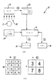
図は、センサ・アレイ14により捉えられた画像を表示するシステム10を例示しており、システム10は、センサ・アレイ14の第1領域内の複数のセンサからの出力に対応する画像16を表示する手段と、センサ・アレイ14内で第1領域を平行移動させ、これにより複数のセンサを変更することによって、表示される画像16を変更する手段とを含む。プロセッサ16は、画像16を表示する手段と、表示される画像を変更する手段とを提供することができる。
The figure illustrates a
図1(A)は、本発明の第1実施態様に従ってセンサ・アレイ14により捉えられた画像を表示するシステム10を例示している。システム10は、センサ・アレイ14として配列された複数のセンサと、バッファ・メモリ22と、プロセッサ16と、ユーザ入力装置24と、ディスプレイ12とメモリ18とを含む。
FIG. 1A illustrates a
システム10は、ディジタル・カメラのコンポーネントであるか、或いはディジタル・カメラにより捉えられた画像を表示するか或いはディジタル・カメラと統合されている電子装置であって良い。システム10は、例えば、移動電話或いはパーソナルデジタルアシスタント(PDA)などの携帯用ハンドヘルド装置で完全に或いは部分的に構成されて良く、或いはパーソナルコンピュータであって良い。
センサ・アレイ14は、任意の適切な光センサを含んでいて良く、例えば、電荷結合素子(CCD)或いは相補型金属酸化膜半導体(CMOS)センサを含むことができる。センサ・アレイは、画像を画像データとして捉える。このデータは、通常は、センサ・アレイ14の各センサについてのデータ・エレメント(ワード)を含む。各データ・エレメントは、夫々のセンサにより感知される光の強さを表す。
The
画像データはセンサ・アレイ14からバッファ・メモリ22へ出力され、これは画像データがプロセッサ16により処理される前に前記画像データを一時的に記憶する。これは、バッファ・メモリ22が溢れるまでシステム10がプロセッサ16の処理速度より大きな速度でデータを捉えることを可能にする。
Image data is output from the
プロセッサ16はユーザ入力装置24に接続され、これからコマンド信号を受け取る。ユーザ入力装置24は、任意の適切なユーザ入力装置であって良くて、例えばキーパッド、ジョイスティック或いは接触感知スクリーンなどであって良い。例示されている例では、ユーザ入力装置24はシステム10の不可欠のコンポーネントである。しかし、他の実施態様では、それは独立して遠くにあって、低電力無線周波数リンクなどの無線リンクを介してプロセッサ16に接続可能であって良い。
The
プロセッサ16は、ディスプレイ12の動作を制御するように接続されている。ディスプレイ12は、任意の適切なディスプレイであって良くて、例えば液晶ディスプレイ(LCD)或いは薄膜トランジスタ(TFT)ディスプレイであって良い。ディスプレイ12の内容は、プロセッサ16により提供されるディスプレイ・データにより決まる。ディスプレイ・データは画像データの部分集合である。
The
プロセッサ16は、メモリ18に読み書きするように接続されている。プロセッサ16は、画像データ及び/又はディスプレイ・データを、将来使用するために前記メモリに記憶させる。メモリ18は、任意の適切なメモリであって良くて、例えばフラッシュ・メモリなどの組み込み永久記憶装置であって良く、或いは、セキュア・ディジタル(SD)カード或いはマイクロ・ドライブなどの取り外し可能なメモリであって良い。
システム10は、複数のセンサ14に入射した光が画像データに変換され、その後に、ディスプレイ12で表示される画像を決定するディスプレイ・データを作るためにユーザ入力装置24からのユーザ入力に応答してプロセッサ16により処理される。
The
より詳しくは、図1(A)は、センサ・アレイ14が少なくとも1つのソース21から光(矢20により表されている)を受け取って画像データ(a)を作ることを例示している。前記センサ・アレイはセンサのN×Mアレイであり、画像データは図1(B)に例示されているようにデータ・エレメントのN×Mアレイとして表されて良く、ここで各データ・エレメントは夫々のセンサ出力に対応する。図1(B)の例では、センサ・アレイはセンサの4×4アレイであり、画像データ(a)は1から16までの番号が付されたデータ・エレメントの4×4アレイとして表されている。画像データはバッファ・メモリ22に記憶される。
More specifically, FIG. 1A illustrates that
プロセッサ16は、バッファ22から画像データを読み出し、これを操作して、図1(B)に例示されているディスプレイ・データ(b)を作る。その操作は、画像データのデータ・エレメントから部分集合を選択することを含む。この部分集合はセンサ・アレイ14の第1領域に対応する。第1領域はセンサ・アレイ14における隣接するセンサのn×m領域であり、部分集合は第1領域内のセンサの出力に対応するnm個のデータ・エレメントである。
画像データ(b)は、次に、ディスプレイ12に送られて表示される。通常、第1領域のサイズ(n×m)はディスプレイのサイズに対応し、ディスプレイ・データの各データ・エレメントはディスプレイのピクセルの強度を制御するために使用される。
The
The image data (b) is then sent to the
図1(B)の例では、ディスプレイはピクセルの2×2アレイであり、第1領域はセンサ・アレイ14の右上隅のセンサの2×2アレイである。従って、表示される画像データは画像データ・エレメント3,4,7,8に対応する。2×2ディスプレイは単なる例示であって、通常は、ディスプレイは遥かに大きくて、例えば1600×1200ピクセル(合計で1,920,000個のピクセル)のアレイである。
In the example of FIG. 1B, the display is a 2 × 2 array of pixels, and the first region is a 2 × 2 array of sensors in the upper right corner of the
ユーザ入力装置24は、ユーザが画像データ(a)を変更せずにディスプレイ・データ(b)を変更することを可能にする。ユーザは、センサ・アレイの異なる領域を表示するようにセンサ・アレイ14内で第1領域を平行移動させることができる。
The
ユーザは、ユーザ入力装置24を使って、画像データのデータ・エレメントから異なる部分集合をディスプレイ・データとして選択することができる。この異なる部分集合は、センサ・アレイ14内での第1領域の平行移動に相当する。例えば、“左”コマンドを提供すれば、第1領域は左へ1だけ平行移動してディスプレイ・データは画像データ・エレメント2,3,6及び7を含むことになる。その代わりとしてユーザが“ダウン”コマンドを提供すれば、第1領域は下へ1だけ平行移動してディスプレイ・データは画像データ・エレメント7,8,11及び12を含むことになる。従って、ユーザは、4×4センサ・アレイ14のどの2×2領域が2×2ディスプレイに入力を提供するのかを選択的に選ぶことができる。これは、ユーザが最後の画像を変更することを望むときにカメラの物理的な動きを減少させるのに役立つであろう。
The user can use the
図2(A)は、本発明の第2実施態様に従ってディスプレイ12を制御するシステム10を例示している。システム10は、図1(A)において例示されているシステム10と実質的に類似していて、類似的に動作する。図2(A)の特徴が図1(A)の特徴と一致する場合には同じ参照数字が使用されている。
FIG. 2A illustrates a
図2(A)に示されているシステム10は、センサ・アレイ14の全センサからの画像データを記憶するためのバッファ・メモリを含んでいない点において図1(A)に示されているものと異なる。この実施態様では、プロセッサ16はセンサ・アレイ14から画像データを選択的に読み出し、それはディスプレイ・データとして使用される。前記ディスプレイ・データは、メモリ18に記憶されても良く、或いはディスプレイ12で表示されてもよい。プロセッサがセンサ・アレイ14の出力を制御するので、システム10はバッファ・メモリ22を含んでいなくても良い。
The
プロセッサ16は、センサ・アレイ内のセンサの部分集合のみから出力を得る。前記部分集合は、センサ・アレイ14の第1領域に対応する。前記第1領域はセンサ・アレイ14内の隣り合うセンサのn×m領域であり、画像データ(ディスプレイ・データ)は、前記第1領域内のセンサの出力に対応するnm個のデータ・エレメントである。
The
ユーザ入力装置24は、ユーザが画像データを変更することによりディスプレイ・データを変えることを可能にする。ユーザは、センサ・アレイ14内の第1領域を平行移動させて、センサ・アレイ14のいろいろな領域からいろいろな画像データを得ることができる。例えば、ディスプレイ・データが始めは図2(B)に示されているように3,4,7,8であり、そしてユーザが“左”コマンドを与えれば、第1領域は左へ1だけ平行移動し、画像データ(ディスプレイ・データ)はデータ・エレメント2,3,6,7を含むことになる。その代わりに、もしユーザが“ダウン”コマンドを与えれば、第1領域は下へ1だけ平行移動し、画像データ(ディスプレイ・データ)はデータ・エレメント7,8,11及び12を含むことになる。従って、ユーザは、4×4センサ・アレイ14のどの2×2領域が2×2ディスプレイに入力を提供するかを選択的に選ぶことができる。
図3(A)は、本発明の第3実施態様に従ってディスプレイ12を制御するためのシステム10を例示している。システム10は、図1(A)に示されているシステム10と類似している。図3(A)の特徴物が図1(A)の特徴物と一致する場合には同じ参照数字が使われている。
センサ・アレイ14は画像データ(a)を捉え、それはプロセッサ16により読み出される。画像データ(a)はMN個のデータ・エレメントを含み、センサ・アレイ14全体の出力に対応する。画像データ(a)はプロセッサ16によりメモリ18に格納される。
FIG. 3A illustrates a
The
後に、ユーザは、記憶されている画像のn×m個のピクセルだけを見たいと述べる要求をプロセッサ16に与えることができる。すると、プロセッサ16は、ディスプレイ12の内容を制御するために使われるディスプレイ・データ(b)を作るために、メモリ18に記憶されている画像データ(a)を処理する。プロセッサ16は、メモリ18からその画像データを読み出し、それを処理してディスプレイ・データ(b)を作る。その処理は、画像データのデータ・エレメントから部分集合を選択することを含む。この部分集合はセンサ・アレイ14の第1領域に対応する。第1領域は、センサ・アレイ14内の隣り合うセンサのn×m領域であり、部分集合は第1領域内のセンサの出力に対応するnm個のデータ・エレメントである。
ディスプレイ・データ(b)は、画像データ(a)とは別のエンティティとしてメモリ18に記憶されて良い。
Later, the user can make a request to the
The display data (b) may be stored in the
図3(B)の例では、ユーザは2×2画像を見ることを選択し、第1領域はセンサ・アレイ14の右上隅内のセンサの2×2アレイである。従って、表示される画像データは画像データ・エレメント3,4,7,8に対応する。2×2アレイは単なる例示であり、通常は、ディスプレイは遥かに大きくて例えば1600×1200ピクセル(合計で1,920,000ピクセル)のアレイである。
ユーザ入力装置24は、ユーザが画像データ(a)を変えずにディスプレイ・データ(b)を変更することを可能にする。
In the example of FIG. 3B, the user chooses to view a 2 × 2 image, and the first region is a 2 × 2 array of sensors in the upper right corner of the
The
ユーザは、記憶されている画像データのデータ・エレメントから異なる部分集合をディスプレイ・データとして選択するためにユーザ入力装置24を使うことができる。この異なる部分集合は、センサ・アレイ14内での第1領域の平行移動に対応する。例えば、もしユーザが“左”コマンドを与えれば、第1領域は左へ1だけ平行移動して、ディスプレイ・データは画像データ・エレメント2,3,6及び7を含むことになる。その代わりに、もしユーザが“ダウン”コマンドを与えれば、第1領域は下へ1だけ平行移動して、ディスプレイ・データは画像データ・エレメント7,8,11及び12を含むことになる。従って、ユーザは4×4センサ・アレイ14のどの2×2領域が2×2ディスプレイに入力を提供するかを選択的に選ぶことができる。
The user can use the
従って、図3(A)に示されているシステム10は、ユーザがセンサ・アレイの全体からの出力を画像データ(a)として捉えて、それをメモリ18に記憶させることを可能にする。それは、その後記憶されている画像(a)を処理してセンサ・アレイの第1領域に対応するディスプレイ・データ(b)を作るようにユーザがプロセッサ16に要求することを可能にする。
Thus, the
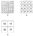
図4は、本発明の実施態様がディジタル・ズームと組み合わされて使用されるときのディスプレイ12からの出力を例示している。画像データ(c)は、1から36までの番号が付された36個のピクセルを含んでいて、センサ・アレイの全領域に対応する。画像(c)が本発明の実施態様に従ってプロセッサ16により処理されるとき、ディスプレイ・データ(d)が作られる。ディスプレイ・データ(d)は、画像データ(c)の右上からの16個のデータ・エレメントを含む。画像(d)は、センサ・アレイの第1領域に対応し、異なる画像を作るようにセンサ・アレイ内で平行移動させられ得る。
FIG. 4 illustrates the output from
画像(d)を、ディジタル・ズームを用いて変化させることができる。ディジタル・ズームは、ユーザがセンサ・アレイの第1領域をリサイズして、リサイズされた画像を作ることを可能にする。リサイズされた画像の中心は、元の画像の中心と一致し、元の画像より大きいか或いは小さくても良い。例えば、もし画像(d)がディジタル・ズームを用いてリサイズされれば、データ・エレメント10,11,16及び17を含むディスプレイ・データ(e)が作られる。ユーザが始めにディジタル・ズームを使用し、次にセンサ・アレイ内で第1領域を平行移動させて新しい画像を作ることができることを当業者は理解するであろう。更に、ディジタル・ズームを本発明の実施態様と同時に使用し得ることも理解されるべきである。
The image (d) can be changed using digital zoom. Digital zoom allows the user to resize the first area of the sensor array to create a resized image. The center of the resized image coincides with the center of the original image and may be larger or smaller than the original image. For example, if image (d) is resized using digital zoom, display data (e) including
前の節では種々の実例を参照して本発明の実施態様を説明したけれども、請求項に記載された発明の範囲から逸脱せずにそれらの実例を改変し得ることが理解されるべきである。例えば、センサ・アレイは上記実例により定められた数に限定されるべきではなくて、複数のセンサと見なされるべきである。同様に、ディスプレイは上記実例に関して記載されたピクセルの数に限定されるべきではなくて、複数のピクセルと見なされるべきである。 Although embodiments of the invention have been described with reference to various examples in the previous section, it should be understood that these examples can be modified without departing from the scope of the claimed invention. . For example, the sensor array should not be limited to the number defined by the above example, but should be considered as multiple sensors. Similarly, the display should not be limited to the number of pixels described with respect to the above example, but should be considered a plurality of pixels.
以上の明細書では本発明の特に重要であると考えられる特徴に注意を引くように努力がなされているけれども、上記の及び/又は図面に示されている特許性のある特徴物又は特徴物の組み合わせに関して、特別の強調がなされていてもいなくても、出願人が保護を請求することが理解されるべきである。 Although an effort has been made in the foregoing specification to draw attention to features that are considered to be of particular importance to the present invention, patentable features or features of the above and / or shown in the drawings It should be understood that the applicant claims protection with or without special emphasis on the combination.
Claims (13)
センサ・アレイの第1領域内の複数のセンサからの出力に対応する画像を表示するための手段と、
前記第1領域を平行移動させることによって前記画像を変化させるための手段と、
を含むことを特徴とするシステム。 A system for displaying an image captured by a sensor array, the system comprising:
Means for displaying an image corresponding to outputs from a plurality of sensors in a first region of the sensor array;
Means for changing the image by translating the first region;
A system characterized by including.
センサ・アレイの第1領域内のセンサからの出力に対応する画像を表示し、
前記センサ・アレイ内の前記第1領域を平行移動させることと同等のユーザ入力に応答して異なる画像を表示することを含むことを特徴とする方法。 A method for displaying an image, the method comprising:
Displaying an image corresponding to the output from the sensors in the first region of the sensor array;
Displaying different images in response to a user input equivalent to translating the first region in the sensor array.
光センサのN×Mアレイを含むセンサから画像を受け取るための入力と、
光センサの前記N×Mアレイのn×m部分集合に対応するピクセルのn×mアレイを含む画像を表示するようにディスプレイを制御するためのプロセッサとを含み、前記対応するn×m部分集合は、表示される画像を変化させるユーザ入力に応答して変更可能であることを特徴とするシステム。 A system for displaying an image, the system comprising:
An input for receiving an image from a sensor comprising an N × M array of light sensors;
A processor for controlling a display to display an image including an n × m array of pixels corresponding to an n × m subset of the N × M array of photosensors, the corresponding n × m subset Is a system that can be changed in response to user input to change the displayed image.
Applications Claiming Priority (2)
| Application Number | Priority Date | Filing Date | Title |
|---|---|---|---|
| US10/798,815 US7232981B2 (en) | 2004-03-10 | 2004-03-10 | System and a method for displaying an image captured by a sensor array |
| US10/798815 | 2004-03-10 |
Publications (2)
| Publication Number | Publication Date |
|---|---|
| JP2005295531A true JP2005295531A (en) | 2005-10-20 |
| JP4906262B2 JP4906262B2 (en) | 2012-03-28 |
Family
ID=34827669
Family Applications (1)
| Application Number | Title | Priority Date | Filing Date |
|---|---|---|---|
| JP2005067375A Expired - Fee Related JP4906262B2 (en) | 2004-03-10 | 2005-03-10 | System and method for displaying an image captured by a sensor array |
Country Status (3)
| Country | Link |
|---|---|
| US (1) | US7232981B2 (en) |
| EP (1) | EP1575280B1 (en) |
| JP (1) | JP4906262B2 (en) |
Families Citing this family (2)
| Publication number | Priority date | Publication date | Assignee | Title |
|---|---|---|---|---|
| US20060005083A1 (en) * | 2004-06-30 | 2006-01-05 | International Business Machines Corporation | Performance count tracing |
| US9219857B2 (en) * | 2011-12-21 | 2015-12-22 | Nokia Technologies Oy | Image capture |
Family Cites Families (6)
| Publication number | Priority date | Publication date | Assignee | Title |
|---|---|---|---|---|
| US5428390A (en) * | 1994-01-21 | 1995-06-27 | Texas Instruments Incorporated | Apparatus and method for focal plane zoom and pan |
| US6512858B2 (en) * | 1998-07-21 | 2003-01-28 | Foveon, Inc. | Image scanning circuitry with row and column addressing for use in electronic cameras |
| EP1047264B1 (en) * | 1999-04-22 | 2007-05-09 | Leo Vision | Method and device for image processing and restitution with resampling |
| JP4443735B2 (en) * | 2000-07-11 | 2010-03-31 | 富士フイルム株式会社 | Imaging apparatus and operation control method thereof |
| US7742073B1 (en) * | 2000-11-01 | 2010-06-22 | Koninklijke Philips Electronics N.V. | Method and apparatus for tracking an object of interest using a camera associated with a hand-held processing device |
| JP3480446B2 (en) * | 2001-01-11 | 2003-12-22 | ミノルタ株式会社 | Digital camera |
-
2004
- 2004-03-10 US US10/798,815 patent/US7232981B2/en not_active Expired - Lifetime
-
2005
- 2005-03-10 EP EP05251468.4A patent/EP1575280B1/en not_active Expired - Lifetime
- 2005-03-10 JP JP2005067375A patent/JP4906262B2/en not_active Expired - Fee Related
Also Published As
| Publication number | Publication date |
|---|---|
| US7232981B2 (en) | 2007-06-19 |
| US20050200735A1 (en) | 2005-09-15 |
| EP1575280A2 (en) | 2005-09-14 |
| JP4906262B2 (en) | 2012-03-28 |
| EP1575280B1 (en) | 2017-08-16 |
| EP1575280A3 (en) | 2010-09-15 |
Similar Documents
| Publication | Publication Date | Title |
|---|---|---|
| JP4395808B2 (en) | Operation device for apparatus having screen display unit, digital camera, and touch panel operation method | |
| US8564624B2 (en) | Image processing apparatus, image processing method, and program | |
| US9485437B2 (en) | Digital photographing apparatus and method of controlling the same | |
| US20140028791A1 (en) | Photographing apparatus for photographing panoramic image and method thereof | |
| KR102629343B1 (en) | Camera module which has multi-cell structure and portable communication device including the camera module | |
| US20100058254A1 (en) | Information Processing Apparatus and Information Processing Method | |
| WO2009145335A1 (en) | Image display apparatus and control method thereof, and computer program | |
| JP2005303728A (en) | Digital camera | |
| JP2006303651A (en) | Electronic equipment | |
| CN101401416A (en) | Image display and storage device, method and medium | |
| CN101263707A (en) | Imaging device, data extraction method, and data extraction program | |
| JP2000341644A (en) | Image processing apparatus and method, and storage medium | |
| JP5836586B2 (en) | Image processing apparatus and image processing method for reading compressed data from memory through data bus | |
| US8803919B2 (en) | Display apparatus and image display method thereof | |
| JP4906262B2 (en) | System and method for displaying an image captured by a sensor array | |
| US8928764B2 (en) | Method and device for correcting user's hand tremor in imaging device | |
| CN101998049A (en) | Display apparatus, display method, and display program | |
| JP2007052795A (en) | Operation device of apparatus provided with screen display part, and digital camera | |
| KR20090095852A (en) | Apparatus for displaying and overlapping a plurality of layers and method for controlling the apparatus | |
| JP7717489B2 (en) | Imaging device | |
| KR102770952B1 (en) | Method for biometric authentication and elecronic device therefor | |
| CN111182200B (en) | Photographing system and photographing system control method | |
| JP2008090034A (en) | Image display program, image display apparatus, and image display method | |
| JP2006148821A (en) | Histogram display apparatus | |
| JP2005333340A (en) | Imaging apparatus |
Legal Events
| Date | Code | Title | Description |
|---|---|---|---|
| A621 | Written request for application examination |
Free format text: JAPANESE INTERMEDIATE CODE: A621 Effective date: 20080108 |
|
| RD02 | Notification of acceptance of power of attorney |
Free format text: JAPANESE INTERMEDIATE CODE: A7422 Effective date: 20090826 |
|
| RD04 | Notification of resignation of power of attorney |
Free format text: JAPANESE INTERMEDIATE CODE: A7424 Effective date: 20090828 |
|
| A131 | Notification of reasons for refusal |
Free format text: JAPANESE INTERMEDIATE CODE: A131 Effective date: 20091023 |
|
| A521 | Request for written amendment filed |
Free format text: JAPANESE INTERMEDIATE CODE: A523 Effective date: 20100123 |
|
| A02 | Decision of refusal |
Free format text: JAPANESE INTERMEDIATE CODE: A02 Effective date: 20100219 |
|
| A01 | Written decision to grant a patent or to grant a registration (utility model) |
Free format text: JAPANESE INTERMEDIATE CODE: A01 |
|
| A61 | First payment of annual fees (during grant procedure) |
Free format text: JAPANESE INTERMEDIATE CODE: A61 Effective date: 20120110 |
|
| FPAY | Renewal fee payment (event date is renewal date of database) |
Free format text: PAYMENT UNTIL: 20150120 Year of fee payment: 3 |
|
| R150 | Certificate of patent or registration of utility model |
Ref document number: 4906262 Country of ref document: JP Free format text: JAPANESE INTERMEDIATE CODE: R150 Free format text: JAPANESE INTERMEDIATE CODE: R150 |
|
| R250 | Receipt of annual fees |
Free format text: JAPANESE INTERMEDIATE CODE: R250 |
|
| S531 | Written request for registration of change of domicile |
Free format text: JAPANESE INTERMEDIATE CODE: R313531 |
|
| R350 | Written notification of registration of transfer |
Free format text: JAPANESE INTERMEDIATE CODE: R350 |
|
| S111 | Request for change of ownership or part of ownership |
Free format text: JAPANESE INTERMEDIATE CODE: R313113 |
|
| R350 | Written notification of registration of transfer |
Free format text: JAPANESE INTERMEDIATE CODE: R350 |
|
| R250 | Receipt of annual fees |
Free format text: JAPANESE INTERMEDIATE CODE: R250 |
|
| R250 | Receipt of annual fees |
Free format text: JAPANESE INTERMEDIATE CODE: R250 |
|
| R250 | Receipt of annual fees |
Free format text: JAPANESE INTERMEDIATE CODE: R250 |
|
| R250 | Receipt of annual fees |
Free format text: JAPANESE INTERMEDIATE CODE: R250 |
|
| R250 | Receipt of annual fees |
Free format text: JAPANESE INTERMEDIATE CODE: R250 |
|
| R250 | Receipt of annual fees |
Free format text: JAPANESE INTERMEDIATE CODE: R250 |
|
| R250 | Receipt of annual fees |
Free format text: JAPANESE INTERMEDIATE CODE: R250 |
|
| R250 | Receipt of annual fees |
Free format text: JAPANESE INTERMEDIATE CODE: R250 |
|
| R250 | Receipt of annual fees |
Free format text: JAPANESE INTERMEDIATE CODE: R250 |
|
| LAPS | Cancellation because of no payment of annual fees |