JP2005295418A - Imaging apparatus and imaging display method - Google Patents
Imaging apparatus and imaging display method Download PDFInfo
- Publication number
- JP2005295418A JP2005295418A JP2004110743A JP2004110743A JP2005295418A JP 2005295418 A JP2005295418 A JP 2005295418A JP 2004110743 A JP2004110743 A JP 2004110743A JP 2004110743 A JP2004110743 A JP 2004110743A JP 2005295418 A JP2005295418 A JP 2005295418A
- Authority
- JP
- Japan
- Prior art keywords
- subject
- display
- frame
- area
- focus
- Prior art date
- Legal status (The legal status is an assumption and is not a legal conclusion. Google has not performed a legal analysis and makes no representation as to the accuracy of the status listed.)
- Pending
Links
Images

Landscapes
- Indication In Cameras, And Counting Of Exposures (AREA)
- Studio Devices (AREA)
Abstract
【課題】撮影画像のより合焦したポイントをユーザに表示する撮像装置および撮像表示方法を提供する。
【解決手段】被写体の撮影時にLCD31に被写体と測距枠32を重畳して表示する。合焦した測距枠の色を変化等させ、合焦枠の位置情報を例えばRAM17に保管する。撮影画像の合焦枠の撮影時に近接合焦領域を有する画像をLCD31に優先的に拡大表示することで、より合焦した領域をユーザに表示することができる。さらに、互いに近接する合焦枠をまとめてLCD31に拡大表示することもでき、これにより合焦枠が複数ある場合でもユーザに拡大表示する画像のステップ数を減らすことができ操作性を向上することができる。
【選択図】 図2
An imaging apparatus and an imaging display method for displaying a more focused point of a captured image to a user.
A subject and a distance measuring frame are superimposed on an LCD and displayed when the subject is photographed. The color of the focused distance measuring frame is changed, and the position information of the focused frame is stored in, for example, the RAM 17. By preferentially enlarging and displaying on the LCD 31 the image having the near-joining focus area when shooting the focus frame of the shot image, the more focused area can be displayed to the user. Furthermore, in-focus frames that are close to each other can be displayed together on the LCD 31 in an enlarged manner, thereby reducing the number of image steps to be enlarged and displayed on the user even when there are a plurality of in-focus frames, thereby improving operability. Can do.
[Selection] Figure 2
Description
この発明は、撮像装置および撮像表示方法に関する。 The present invention relates to an imaging apparatus and an imaging display method.
近年、ディジタルカメラやカムコーダ(camcoder:camera and recorderを略した用語)などと称される撮像装置が広く普及している。このような撮像装置には、撮影時にピントを合わせたり、撮影時のカメラアングルを調整するために、撮影画像を表示する例えば液晶モニタが設けられることが多い。 In recent years, imaging devices called digital cameras and camcorders (abbreviations for camera and recorder) have been widely used. Such an image pickup apparatus is often provided with, for example, a liquid crystal monitor for displaying a shot image in order to focus at the time of shooting or to adjust a camera angle at the time of shooting.
また、最近ではユーザが撮影対象の画像のピントをより容易に合わせることができるように液晶モニタに測距枠を表示し、合焦した測距枠の色を変えたり、合焦した測距枠だけを表示することがなされている。また、被写体の合焦した箇所(合焦領域)の確認を容易にするために、再生時に合焦領域を拡大して表示することも行われており、合焦領域が複数ある場合は、切り替えて表示することができるようにされている。 In addition, recently, a range-finding frame is displayed on the LCD monitor so that the user can more easily focus on the image to be shot, and the color of the focused range-finding frame is changed, or the focused range-finding frame is displayed. It has been made to display only. In addition, in order to make it easier to confirm the in-focus area (in-focus area) of the subject, the in-focus area is enlarged and displayed at the time of playback. Can be displayed.
下記の特許文献1には、主として以下の内容が記載されている。
・撮影後に合焦した付近の画像を画面全体に表示する。
・AF(Auto Focus)マルチ枠機能の場合に合焦した付近の画像を全体に拡大表示する。
・視線判別でも行う。
・拡大表示した結果を確認し、撮影画像の削除を行える。
・拡大表示した画像と本画像を記録媒体に関連付けて記録できる。
・シャッターの半押し時に拡大し、深押しで記録できる。
The following contents are mainly described in Patent Document 1 below.
・ Displays the image near the focus after shooting on the entire screen.
-When the AF (Auto Focus) multi-frame function is used, the image near the focus is enlarged and displayed.
・ Perform gaze discrimination.
-You can check the enlarged display result and delete the shot image.
-The enlarged image and the main image can be recorded in association with the recording medium.
-Enlarges when the shutter is half-pressed, and records when pressed deep.
下記の特許文献2には、主として以下の内容が記載されている。
・合焦した部分を拡大表示するモードと本画像を表示するモードを切り替えることができる。
・合焦した部分の拡大表示が複数有り、ユーザの操作により切り替える手段がある。
-It is possible to switch between a mode for enlarging the focused portion and a mode for displaying the main image.
There are a plurality of enlarged displays of the focused part, and there is means for switching by the user's operation.
下記の特許文献3には、主として以下の内容が記載されている。
・合焦した枠範囲を拡大表示する。
・再生で合焦情報をもとに、合焦した枠範囲を拡大表示する。
・拡大する領域はユーザによって設定が可能である。
・拡大率や表示位置の設定も可能である。
・拡大表示中にユーザ設定が変えられる。
・全画像表示と部分拡大画像を切り替えることを指示する表示モード指示手段がある。
The following contents are mainly described in Patent Document 3 below.
-Zoom in on the focused frame range.
-Enlarge and display the focused frame range based on the focus information during playback.
-The area to be enlarged can be set by the user.
-It is possible to set the enlargement ratio and display position.
-User settings can be changed during enlarged display.
There is display mode instruction means for instructing to switch between full image display and partially enlarged image.
しかしながら、近年、撮影画像のピントをより細かく合わせるために測距枠の増加や配列の複雑化、測距枠の小型化が進んでおり、合焦領域を示す測距枠(以下、適宜、合焦枠と称する)の数が多くなる場合がある。従来の合焦枠の表示方法では、合焦枠が多くなると拡大表示する画像の数も多くなり、画像の切り替えがステップ数の増加により煩雑となってしまう。例えば、10点の近接した合焦枠がある場合に、10箇所の合焦枠を拡大表示し、切り替えて各画像を確認することは、ユーザにとってかなりの負担となる。 However, in recent years, in order to focus the captured image more finely, the distance measurement frame has been increased, the arrangement has been complicated, and the distance measurement frame has been downsized. In some cases, the number of frames is referred to as a focal frame. In the conventional method of displaying a focusing frame, the number of images to be enlarged increases as the number of focusing frames increases, and switching of images becomes complicated due to an increase in the number of steps. For example, when there are 10 in-focus frames, it is a considerable burden on the user to enlarge and display 10 in-focus frames and switch to check each image.
従ってこの発明の目的は、合焦枠が複数ある場合は、合焦評価値が高い合焦枠を優先的に拡大表示する撮像装置および撮像表示方法を提供することである。 Accordingly, an object of the present invention is to provide an imaging apparatus and an imaging display method that preferentially enlarge and display a focusing frame having a high focusing evaluation value when there are a plurality of focusing frames.
この発明の他の目的は、合焦枠の数が多く存在してもユーザの設定した比率によりまとめることでステップ数の増加を防ぎ、ユーザの負担を軽減できる撮像装置および撮像表示方法を提供することである。 Another object of the present invention is to provide an imaging apparatus and an imaging display method capable of preventing an increase in the number of steps by reducing the burden on the user by collecting them according to a ratio set by the user even when there are many in-focus frames. That is.
この発明の他の目的は、合焦枠の数が多く存在しても、画像のフォーカスを素早くかつ容易に確認できる撮像装置および撮像表示方法を提供することである。 Another object of the present invention is to provide an imaging apparatus and an imaging display method capable of quickly and easily confirming the focus of an image even when there are many focusing frames.
上述した課題を解決するために、請求項1に係る発明は、被写体を撮影し、被写体の画像データを表示する表示部を備えた撮像装置において、被写体の撮影時に表示部には、被写体と被写体の合焦領域を示す表示枠が重畳して表示され、画像データの再生時に、近接合焦領域をより多く有する表示枠を優先的に拡大表示するようにした撮像装置である。 In order to solve the above-described problem, the invention according to claim 1 is directed to an imaging apparatus including a display unit that captures a subject and displays image data of the subject. In this imaging apparatus, a display frame indicating the in-focus area is superimposed and displayed, and a display frame having a larger number of near-joining focus areas is preferentially enlarged and displayed when image data is reproduced.
請求項3に係る発明は、被写体を撮影し、被写体の画像データを表示する表示部を備えた撮像装置において、被写体の撮影時に表示部には、被写体と被写体の合焦領域を示す表示枠が重畳して表示され、画像データの再生時に、合焦領域を示す表示枠が互いに近接しているか否かを判別し、近接している場合には、互いに近接する複数の表示枠の全てを含む領域を設定し、設定された領域を優先的に拡大表示するようにした撮像装置である。 According to a third aspect of the present invention, in the imaging apparatus including a display unit that captures a subject and displays image data of the subject, the display unit includes a display frame that indicates a focus area between the subject and the subject when the subject is captured. When the image data is reproduced, it is determined whether or not the display frames indicating the in-focus area are close to each other, and if they are close, all of the plurality of display frames that are close to each other are included. This is an imaging apparatus in which an area is set and the set area is preferentially enlarged and displayed.
請求項6に係る発明は、被写体を撮影し、被写体の画像データを表示部に表示する撮像表示方法において、被写体の撮影時に表示部に、被写体と被写体の合焦領域を示す表示枠が重畳して表示されるステップと、画像データの再生時に、近接合焦領域をより多く有する表示枠を優先的に表示するステップを含む撮像表示方法である。 According to a sixth aspect of the present invention, in an imaging display method for photographing a subject and displaying image data of the subject on a display unit, a display frame indicating a subject and a focusing area of the subject is superimposed on the display unit when the subject is photographed. And a step of preferentially displaying a display frame having a larger number of near-joining focal regions when reproducing the image data.
請求項7に係る発明は、被写体を撮影し、被写体の画像データを表示部に表示する撮像表示方法において、被写体の撮影時に表示部には、被写体と被写体の合焦領域を示す表示枠が重畳して表示されるステップと、画像データの再生時に、合焦領域を示す表示枠が互いに近接しているか否かを判別するステップと、近接している場合に、互いに近接する複数の表示枠の全てを含む領域を設定するステップと、設定された領域を優先的に拡大表示するステップを含む撮像表示方法である。 According to a seventh aspect of the present invention, in the imaging display method for photographing a subject and displaying image data of the subject on a display unit, a display frame indicating a subject and a focus area of the subject is superimposed on the display unit when the subject is photographed. The display step, the step of determining whether or not the display frames indicating the in-focus area are close to each other when the image data is reproduced, and a plurality of display frames that are close to each other when close to each other. This is an imaging display method including a step of setting an area including all and a step of preferentially enlarging and displaying the set area.
この発明によれば、合焦枠が一つの場合と複数の場合とでユーザに対する表示の仕方を自動で変えることにより、ユーザは、被写体の合焦ポイントを容易に認識できる。また、合焦枠が複数の場合でも、合焦の評価値が高い画像が優先的に拡大表示されるので、ユーザの意識をより合焦している領域へ誘導することが可能となる。 According to the present invention, the user can easily recognize the in-focus point of the subject by automatically changing the display method for the user depending on whether the focus frame is one or more. Even when there are a plurality of focusing frames, an image with a high focusing evaluation value is preferentially enlarged and displayed, so that the user's consciousness can be guided to a more focused area.
この発明によれば、近接する複数の合焦枠がある場合でも、複数の合焦枠をまとめて領域を設定し、更に設定した領域を拡大する倍率と中心とを自動で制御することにより、ユーザに対して拡大表示する画面のステップ数を削減することができ、操作性を向上することができる。 According to the present invention, even when there are a plurality of adjacent focusing frames, by setting a plurality of focusing frames and setting a region, and further automatically controlling a magnification and a center for enlarging the set region, It is possible to reduce the number of steps on the screen to be enlarged and displayed for the user, and to improve operability.
以下、図面を参照しながらこの発明の一実施形態について説明する。この一実施形態では、撮像装置をディジタル電子スチルカメラ(以下、適宜、ディジタルカメラと称する)として説明するが、ディジタルカメラに限定されるわけではなく、カムコーダ等の他の撮像装置にもこの発明を適用することができる。 Hereinafter, an embodiment of the present invention will be described with reference to the drawings. In this embodiment, the image pickup apparatus is described as a digital electronic still camera (hereinafter referred to as a digital camera as appropriate), but the present invention is not limited to a digital camera, and the present invention is applied to other image pickup apparatuses such as a camcorder. Can be applied.
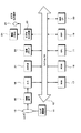
図1は、この一実施形態におけるディジタルカメラの全体構成を示す。ディジタルカメラの全体的な制御はCPU(Central Processing Unit)11により行われる。また、CPU11の指示信号や各周辺デバイスのデータのやり取りはシステムバス12を経由して行われる。システムバス12には、アドレスバスとデータバスが含まれる。各種データはRAM(Random Access Memory)17に展開され、処理が施される。また、ディジタルカメラの制御プログラムは、ROM(Reed Only Memory)18に格納される。
FIG. 1 shows the overall configuration of a digital camera according to this embodiment. Overall control of the digital camera is performed by a CPU (Central Processing Unit) 11. In addition, the exchange of instruction signals from the
参照符号13はレンズを示す。レンズ13はレンズ駆動部14により制御され、フォーカシング動作を行う。被写体が暗い場合にはストロボ21が発光する。レンズ13から取り込まれた被写体光は、撮像素子、例えばCCD(Charge Coupled Device)15に供給される。CCD15に供給された光は露光され、AGC(Automatic Gain Control)回路(図示しない)に供給される。AGC回路の出力信号がA/D(Analog to Digital)コンバータ16によってディジタル画像データに変換され、変換されたディジタル画像データはシステムバス12を経由して、RAM17に格納される。
RAM17に格納されたディジタル画像データは、DSP(Digital Signal Processor)19によって例えば、ガンマ補正、輪郭補償などの信号処理が施される。また、DSP19では静止画として取り込まれたディジタル画像データに対してJPEG(Joint Photographic Experts Group)などの圧縮処理もなされる。圧縮されたディジタル画像データは、必要に応じて一旦RAM17に取り込まれ、不揮発性デバイスである記録メディア22に保存される。記録メディア22は、例えばメモリーカードなどディジタルカメラに着脱可能とされている記録メディアである。
The digital image data stored in the
撮影時に被写体をフレーミングするためのモニタリング画像や、撮影画像の再生時に記録メディア22から読み出されたディジタル画像データは、ビデオ出力回路23を介して液晶パネル24(LCD(Liquid Crystal Display))に表示される。ビデオ出力回路23の出力は、ビデオ出力端子25に対しても供給されるので、ビデオ出力端子25と接続された外部モニタにディジタル画像データを表示することができる。また、参照符号20は外部インターフェイスを示し、例えばノート型パーソナルコンピュータなどの外部機器と接続される。
A monitoring image for framing a subject at the time of shooting and digital image data read from the
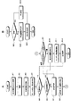
図2は、この一実施形態における撮像装置の動作のフローチャートである。適宜、図3〜図7を参照して、図2のフローチャートを説明する。ステップS1では、ユーザにより、まとめ処理がONまたはOFFに設定される。まとめ処理のON/OFFは、例えばディジタルカメラに設けられた切替スイッチなどを用いて行われる。尚、まとめ処理の詳細については後述する。まとめ処理の設定がされた後に動作はステップS2に進み、被写体の撮影が行われる。 FIG. 2 is a flowchart of the operation of the imaging apparatus according to this embodiment. The flowchart of FIG. 2 will be described with reference to FIGS. In step S1, the summary process is set to ON or OFF by the user. The summary processing is turned on / off using, for example, a changeover switch provided in the digital camera. Details of the summarization process will be described later. After the summarization process is set, the operation proceeds to step S2, and the subject is photographed.
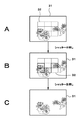
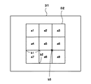
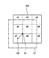
ステップS2の撮影処理の一例について図3を参照して説明する。図3Aに示すように撮影時には、LCD31に被写体と表示枠としての測距枠32が重畳して表示される。図5は測距枠32の一例である。この一実施形態では、測距枠32を3枠×3枠の計9個の枠からなる測距枠32とし、測距枠32を構成するそれぞれの枠に対して図6の参照符号a1〜a9を付して示す。
An example of the photographing process in step S2 will be described with reference to FIG. As shown in FIG. 3A, at the time of shooting, a subject and a
LCD31内にユーザの所望する被写体が表示された後、ディジタルカメラのシャッターを半押しすると自動的にフォーカシングが行われる(所謂、AF(Auto Focus)機能)。オートフォーカスの方法は種々の方法があるが、例えばA/Dコンバータ16のディジタル出力信号の高周波成分を1フィールド積分し、積分値が最大になるようにフィードバックする方法がある。フィードバックされた情報をCPU11で処理し、レンズ駆動部14を制御し、レンズ13の位置を制御して焦点を合わせる。
After the subject desired by the user is displayed on the
AFが行われると、図3Bに示すように各辺が太く表示された測距枠が表示される。各辺が太く表示された測距枠が合焦枠である。この一実施形態では、図3Bに示すように、測距枠a4、測距枠a6、測距枠a7および測距枠a8が合焦枠となる。 When AF is performed, as shown in FIG. 3B, a distance measuring frame with thick sides is displayed. A focusing frame with each side displayed thick is a focusing frame. In this embodiment, as shown in FIG. 3B, the distance measurement frame a4, the distance measurement frame a6, the distance measurement frame a7, and the distance measurement frame a8 are the focusing frames.
合焦枠の表示により合焦ポイントを確認した後、ユーザは半押し状態のシャッターを全押しすることにより撮影を行う(ステップS2)。撮影が終了すると、動作はステップS3へ進む。ステップS3では、合焦情報が例えばRAM17などの一時保管領域に格納される。ここで合焦情報とは、9つの測距枠のうちどこの測距枠が合焦しているかという合焦枠の位置情報を意味する。
After confirming the in-focus point by displaying the in-focus frame, the user performs shooting by fully pressing the shutter in the half-pressed state (step S2). When shooting is finished, the operation proceeds to step S3. In step S3, the focus information is stored in a temporary storage area such as the
ステップS4では、ステップS2で撮影された画像の合焦ポイントの確認のため、オートレビューまたは再生が行われ、合焦枠の画像がLCD31に拡大表示される。オートレビューとは撮影した画像の合焦枠の画像を、自動的にLCD31に拡大表示する処理である。合焦枠の画像の拡大表示はユーザによるマニュアル操作によって表示されるようにしてもよい。ユーザに合焦枠の画像をLCD31に拡大表示する際にステップS5以降の処理がなされる。
In step S4, auto review or reproduction is performed to confirm the in-focus point of the image captured in step S2, and the image of the in-focus frame is enlarged and displayed on the
ステップS5では合焦枠の数が一つか否かが判別される。合焦枠が一つであれば動作はステップS12に進み、合焦枠の画像が所定の割合で拡大されてLCD31に表示され動作は終了する。合焦枠が複数箇所有る場合は、動作はステップS6に進む。
In step S5, it is determined whether or not the number of focusing frames is one. If there is one in-focus frame, the operation proceeds to step S12, the image of the in-focus frame is enlarged at a predetermined rate and displayed on the
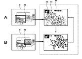
ステップS6では、まとめ処理がON又はOFFであるかが判別される。ステップS6でまとめ処理がOFFと判別された場合になされる処理(ステップS10〜ステップS12)について図4を用いて説明する。尚、図4においても図3と同じように、9つの測距枠のうち測距枠a4、測距枠a6、測距枠a7および測距枠a8を合焦枠として説明する。 In step S6, it is determined whether the summary process is ON or OFF. Processing performed when it is determined in step S6 that the summary processing is OFF (steps S10 to S12) will be described with reference to FIG. In FIG. 4, as in FIG. 3, the distance measurement frame a4, the distance measurement frame a6, the distance measurement frame a7, and the distance measurement frame a8 out of the nine distance measurement frames will be described.
ステップS10では4つの合焦枠の画像を拡大表示する順番が決定される。合焦枠が複数箇所ある場合は、近接合焦領域を有する合焦枠を優先的に表示する。近接合焦領域を有する合焦枠を優先的に表示するのは、他の合焦枠に比べ、合焦ポイントがより密であり、合焦の評価値が高いと判別されるためである。 In step S10, the order in which the images of the four focusing frames are enlarged and displayed is determined. When there are a plurality of in-focus frames, the in-focus frame having the near joint focus area is preferentially displayed. The reason why the focus frame having the near-joining focus area is preferentially displayed is that it is determined that the focus point is denser and the focus evaluation value is higher than the other focus frames.
ここで、近接合焦領域について説明する。近接とは、合焦枠同士が互いに辺を共有することをいう。図5を用いてより具体的に説明すると、例えば合焦枠a4は、合焦枠a7は辺b1で接しており、互いに辺b1を共有する。即ち合焦枠a4は合焦枠a7と近接している。また、合焦枠a7は、辺b1を合焦枠a4と共有し、また辺b2を合焦枠a8と共有しているから、合焦枠a4および合焦枠a8と近接しており、近接する合焦枠の数(以下,適宜、近接合焦領域と称する)は2つとなる。同様に、合焦枠a8は辺b2を合焦枠a7と共有しており、近接している。しかしながら、合焦枠a6は近接合焦領域を有しない。合焦枠a6は、辺を共有する他の合焦枠を有しないからである。尚、合焦枠a6は合焦枠a8と頂点b3で接するが、辺を共有していないので合焦枠a8とは近接していない。 Here, the near-joining focal region will be described. Proximity means that the focusing frames share sides. More specifically, for example, the focusing frame a4 is in contact with the focusing frame a7 at the side b1 and shares the side b1 with each other. That is, the focusing frame a4 is close to the focusing frame a7. Further, since the focusing frame a7 shares the side b1 with the focusing frame a4 and also shares the side b2 with the focusing frame a8, the focusing frame a7 is close to the focusing frame a4 and the focusing frame a8. The number of focusing frames to be performed (hereinafter referred to as a near-joining focal region as appropriate) is two. Similarly, the focusing frame a8 shares the side b2 with the focusing frame a7 and is close to it. However, the focusing frame a6 does not have a near-joining focal region. This is because the focusing frame a6 has no other focusing frame sharing the side. Note that the focusing frame a6 is in contact with the focusing frame a8 at the apex b3, but is not adjacent to the focusing frame a8 because the side is not shared.
ステップS10では、近接合焦領域を有する合焦枠a4、合焦枠a7、合焦枠a8をそれぞれ優先的に表示するように順番が決定される。図4の破線内に示すようにLCD31には例えば、合焦枠a4→合焦枠a7→合焦枠a8→合焦枠a6の順にLCD31に各合焦枠の画像が拡大表示される。画面の切替はユーザの操作により行うことができる。また、合焦枠が複数あるため、LCD31にどの合焦枠が拡大表示されているかをユーザにわかるようにすることもできる。例えば、参照符号33に示すように4枚のうちの1枚目という意味で1/4などと表示してもよい。また、拡大表示している合焦枠の原画像における位置をアイコン34により確認できるようにしてもよい。
In step S10, the order is determined so that the focusing frame a4, the focusing frame a7, and the focusing frame a8 having the near-joining focus area are displayed with priority. As shown in the broken line in FIG. 4, on the
近接合焦領域を有する合焦枠a4、合焦枠a7、合焦枠a8はいずれから表示してもよいが、この発明ではより近接合焦領域を多く有する画像を優先的に拡大表示するようにするようにしてもよい。合焦枠a7は、合焦枠a4および合焦枠a8に比べて近接合焦領域を2つ有していることからより合焦の評価値が高いと判別することができる。従って、ステップS10における表示の順番を決定するステップで、より近接合焦領域を多く有する合焦枠a7の拡大画像が先に表示されるようにしてもよい。 Although the focusing frame a4, the focusing frame a7, and the focusing frame a8 having the near-joining focus area may be displayed from any of them, in the present invention, an image having more close-joining focus areas is preferentially enlarged and displayed. You may make it. Since the focusing frame a7 has two near-joining focal regions compared to the focusing frame a4 and the focusing frame a8, it can be determined that the evaluation value of focusing is higher. Therefore, in the step of determining the display order in step S10, an enlarged image of the focusing frame a7 having more near-joining focal regions may be displayed first.
ステップS11では、表示された4つの拡大画像をユーザが選択する。選択された画像が、ステップS12でLCD31に拡大表示され、動作は終了する。
In step S11, the user selects four displayed enlarged images. The selected image is enlarged and displayed on the
次に、ステップS6でまとめ処理がONされている場合の動作について説明する。ステップS6でまとめ処理がONと判別されると動作はS7に進み、まとめ処理がされる。まとめ処理とは、合焦枠の数が多い場合にユーザの切り替えるステップ数を少なくするため複数の合焦枠をまとめて表示する処理をいう。ステップS7でまとめ判定がなされ、動作はステップS8に進み拡大率および中心座標の決定がされる。 Next, the operation when the summarization process is turned on in step S6 will be described. If it is determined in step S6 that the summarization process is ON, the operation proceeds to S7, where the summarization process is performed. The summarization process refers to a process of displaying a plurality of focusing frames collectively in order to reduce the number of steps to be switched by the user when the number of focusing frames is large. In step S7, a summary determination is made, and the operation proceeds to step S8 where the enlargement ratio and center coordinates are determined.
ステップS7およびステップS8におけるまとめ処理を図2Bのフローチャートを用いて説明する。この一実施形態では、それぞれ近接合焦領域を有する合焦枠a4、合焦枠a7、合焦枠a8をまとめ処理するものとする。ステップS21でまとめ処理される対象の合焦枠により構成される図形が矩形か否かが判別される。矩形であれば動作はステップS23に進み、矩形の中心が決定される。中心が決定されると動作はステップS24に進む。ステップS24では、矩形を構成する合焦枠の数によりLCD31に拡大表示される拡大率が自動的に決定される。
The summary process in step S7 and step S8 will be described with reference to the flowchart of FIG. 2B. In this embodiment, it is assumed that the focusing frame a4, the focusing frame a7, and the focusing frame a8 each having a near joint focusing area are processed together. In step S21, it is determined whether or not the figure formed by the focusing frame to be processed collectively is a rectangle. If it is a rectangle, the operation proceeds to step S23, and the center of the rectangle is determined. When the center is determined, the operation proceeds to step S24. In step S24, the enlargement ratio to be enlarged and displayed on the
ステップS21において、矩形でないと判別された場合は、動作はステップS22に進む。この一実施形態においてまとめ処理される3つの合焦枠(合焦枠a4、合焦枠a7、合焦枠a8)により構成される図形はL字状であり矩形でないため、動作はステップS22に進む。ステップS22およびステップS24の動作を、図6を参照して説明する。 If it is determined in step S21 that the object is not rectangular, the operation proceeds to step S22. In this embodiment, since the figure constituted by the three focusing frames (the focusing frame a4, the focusing frame a7, and the focusing frame a8) that are collectively processed is L-shaped and not rectangular, the operation proceeds to step S22. move on. The operation of step S22 and step S24 will be described with reference to FIG.
ステップS22では、図6に示すように、はじめに3つの合焦枠(合焦枠a4、合焦枠a7、合焦枠a8)全てを含む矩形を作成し、拡大表示するための原画像における領域の大きさC1(以下、領域C1と称する)が設定される。領域C1の最大領域は、例えば4枠分までのように任意に設定することができるようにしてもよい。 In step S22, as shown in FIG. 6, first, a rectangle including all three focusing frames (a focusing frame a4, a focusing frame a7, and a focusing frame a8) is created and an area in the original image for enlarged display. Is set to C1 (hereinafter referred to as region C1). The maximum area of the area C1 may be arbitrarily set, for example, up to four frames.
領域C1をLCD31に拡大表示することもできるが、領域C1の中心座標を移動させることもできる。例えば領域C1の中心座標をD1とすると、中心D1は合焦枠a7の中心D2若しくはその周辺に移動される。合焦枠a7の中心D2付近にD1を移動させるのは、上述したように合焦枠a7は近接合焦領域を2つ有し、他の合焦枠よりも合焦評価値が高いと判別されるため、合焦枠a7を中心にしてLCD31に拡大表示するためである。
The area C1 can be enlarged and displayed on the
中心座標がD1からD2付近に移動したことにより、3つの合焦枠のいずれかが領域C1を外れた場合は、D2付近を中心として3つの合焦枠を含む領域が設定される。中心座標が決定された後に動作はステップS24へ進む。ステップS24ではLCD31に表示するための拡大率が決定され、動作は終了する。
If any of the three in-focus frames deviates from the area C1 due to the movement of the center coordinate from D1 to D2, an area including the three in-focus frames is set around D2. After the center coordinates are determined, the operation proceeds to step S24. In step S24, an enlargement ratio for display on the
上述したステップS7およびステップS8の後に、動作はステップS9へ進む。ステップS9では、まとめ処理がまだ必要か否かが判別される。この一実施形態では、まとめ処理を1回だけ行ったが、合焦枠のそれぞれの位置によってはまとめ処理を数回施した方が拡大表示のステップをより減らすことができる場合がある。例えば、合焦枠がa3、a4、a6、a7の場合は合焦枠a3と合焦枠a6および合焦枠a4と合焦枠a7のようにそれぞれに対してまとめ処理を施すことも可能である。ステップS9でまとめ処理が必要と判別されればステップS7およびステップS8の動作を繰り返す。 After step S7 and step S8 described above, the operation proceeds to step S9. In step S9, it is determined whether the summarization process is still necessary. In this embodiment, the summarization process is performed only once. However, depending on the position of the focusing frame, the enlargement display step may be further reduced by performing the summarization process several times. For example, when the in-focus frames are a3, a4, a6, and a7, it is also possible to perform a collective process on each of the in-focus frames a3 and a6 and the in-focus frames a4 and a7. is there. If it is determined in step S9 that the summarization process is necessary, the operations in steps S7 and S8 are repeated.
ステップS9でまとめ処理が不要と判別されると、動作はステップS10に進む。ステップS10では、表示される画像の順番が決められる。図7の破線内に示すように、3つの合焦枠がまとめ処理された領域C1の拡大画像が、合焦評価値が高いため先に表示される。続いて、合焦枠a6が拡大表示される。ステップS11では、拡大表示された画像をユーザが選択し、ステップS12では選択された画像がLCD31に拡大表示される。
If it is determined in step S9 that the summarization process is unnecessary, the operation proceeds to step S10. In step S10, the order of images to be displayed is determined. As shown in the broken line in FIG. 7, the enlarged image of the area C1 in which the three focusing frames are processed together is displayed first because the focusing evaluation value is high. Subsequently, the focusing frame a6 is enlarged and displayed. In step S11, the user selects an enlarged image, and in step S12, the selected image is enlarged and displayed on the
この発明は、この発明の要旨を逸脱しない範囲内でさまざまな変形や応用が可能であり、上述した一実施形態に限定されることはない。例えば、撮影した本画像が非常に大きいと拡大画像も大きくなってしまうので、拡大画像をフォーカスが確認できる程度に縮小し、例えばRAMや記録メディアに保存してもよい。 The present invention can be variously modified and applied without departing from the gist of the present invention, and is not limited to the above-described embodiment. For example, if the photographed main image is very large, the enlarged image also becomes large. Therefore, the enlarged image may be reduced to such an extent that the focus can be confirmed, and stored in, for example, a RAM or a recording medium.
また、保管画像を呼び出すモードを設け、保管画像を順次見ていくことを可能としてもよい。その際に、削除する機能をユーザに提供し、削除した場合には関連する本画像も削除できるようにしてもよい。また、再生時に視線検出装置を利用すれば、画像の合焦ポイントを見ることで画像の拡大表示をするモードに切り替えることができる。 Further, a mode for calling a stored image may be provided so that the stored images can be viewed sequentially. At that time, a function to be deleted may be provided to the user so that the related main image can be deleted. In addition, if the line-of-sight detection device is used during reproduction, it is possible to switch to a mode in which an image is enlarged and displayed by looking at the in-focus point of the image.
また、ディジタル電子スチルカメラに内蔵されている内蔵メモリから通信手段によりパーソナルコンピュータなどの情報処理装置に画像を取り込むことができる。また、パーソナルコンピュータに画像を移動するときに本画像だけを移動し、同時に拡大画像を削除できるようにしてもよい。 Further, an image can be taken into an information processing apparatus such as a personal computer from a built-in memory built in the digital electronic still camera by communication means. Alternatively, when moving the image to the personal computer, only the main image may be moved and at the same time the enlarged image may be deleted.
また、2つのカメラを内蔵していて一度に撮影できるカメラの場合に主カメラの合焦ポイントから一番遠い箇所に副カメラの画像を合成するものがある。このようなカメラに対してこの発明を適用すれば、主カメラの合焦位置および合焦評価を容易に決定することができるので、合焦ポイントを避けて副カメラの画像を合成することができる。 In the case of a camera that has two cameras and can be photographed at one time, there is one that synthesizes the image of the sub camera at a position farthest from the focus point of the main camera. If the present invention is applied to such a camera, the in-focus position and the in-focus evaluation of the main camera can be easily determined, so that the sub-camera image can be synthesized while avoiding the in-focus point. .
11 CPU
12 システムバス
19 DSP
31 LCD
32 測距枠
11 CPU
12
31 LCD
32 Distance measurement frame
Claims (8)
上記被写体の撮影時に上記表示部には、上記被写体と上記被写体の合焦領域を示す表示枠が重畳して表示され、
上記画像データの再生時に、近接合焦領域をより多く有する表示枠を優先的に拡大表示するようにした撮像装置。 In an imaging device including a display unit that captures a subject and displays image data of the subject,
When the subject is photographed, the display unit displays a display frame indicating the subject and the focus area of the subject in an overlapping manner,
An image pickup apparatus that preferentially enlarges and displays a display frame having a larger number of near-joining focal regions when reproducing the image data.
上記被写体の撮影時に上記表示部には、上記被写体と上記被写体の合焦領域を示す表示枠が重畳して表示され、
上記画像データの再生時に、上記合焦領域を示す表示枠が互いに近接しているか否かを判別し、近接している場合には、互いに近接する複数の表示枠の全てを含む領域を設定し、上記設定された領域を優先的に拡大表示するようにした撮像装置。 In an imaging device including a display unit that captures a subject and displays image data of the subject,
When the subject is photographed, the display unit displays a display frame indicating the subject and the focus area of the subject in an overlapping manner,
When reproducing the image data, it is determined whether or not the display frames indicating the in-focus area are close to each other. If they are close to each other, an area including all of the plurality of display frames close to each other is set. An image pickup apparatus that preferentially enlarges and displays the set area.
上記被写体の撮影時に上記表示部に、上記被写体と上記被写体の合焦領域を示す表示枠が重畳して表示されるステップと、
上記画像データの再生時に、近接合焦領域をより多く有する表示枠を優先的に表示するステップを含む撮像表示方法。 In an imaging display method for photographing a subject and displaying image data of the subject on a display unit,
A step of displaying a display frame indicating the subject and a focusing area of the subject superimposed on the display unit when the subject is photographed;
An imaging display method including a step of preferentially displaying a display frame having a larger number of near-joining focal regions when reproducing the image data.
上記被写体の撮影時に上記表示部には、上記被写体と上記被写体の合焦領域を示す表示枠が重畳して表示されるステップと、
上記画像データの再生時に、上記合焦領域を示す表示枠が互いに近接しているか否かを判別するステップと、
近接している場合に、互いに近接する複数の表示枠の全てを含む領域を設定するステップと、
上記設定された領域を優先的に拡大表示するステップを含む撮像表示方法。 In an imaging display method for photographing a subject and displaying image data of the subject on a display unit,
A step of superimposing and displaying a display frame indicating the subject and a focusing area of the subject on the display unit when photographing the subject;
Determining whether or not display frames indicating the in-focus area are close to each other during reproduction of the image data;
A step of setting an area including all of a plurality of display frames that are close to each other when close to each other;
An imaging display method including a step of preferentially enlarging and displaying the set area.
The imaging display method according to claim 7, wherein the area is set so that a center is brought close to an approximate center of a display frame having the largest number of near-joining focal areas among the plurality of display frames close to each other.
Priority Applications (1)
| Application Number | Priority Date | Filing Date | Title |
|---|---|---|---|
| JP2004110743A JP2005295418A (en) | 2004-04-05 | 2004-04-05 | Imaging apparatus and imaging display method |
Applications Claiming Priority (1)
| Application Number | Priority Date | Filing Date | Title |
|---|---|---|---|
| JP2004110743A JP2005295418A (en) | 2004-04-05 | 2004-04-05 | Imaging apparatus and imaging display method |
Publications (1)
| Publication Number | Publication Date |
|---|---|
| JP2005295418A true JP2005295418A (en) | 2005-10-20 |
Family
ID=35327828
Family Applications (1)
| Application Number | Title | Priority Date | Filing Date |
|---|---|---|---|
| JP2004110743A Pending JP2005295418A (en) | 2004-04-05 | 2004-04-05 | Imaging apparatus and imaging display method |
Country Status (1)
| Country | Link |
|---|---|
| JP (1) | JP2005295418A (en) |
Cited By (13)
| Publication number | Priority date | Publication date | Assignee | Title |
|---|---|---|---|---|
| JP2007208717A (en) * | 2006-02-02 | 2007-08-16 | Canon Inc | Imaging apparatus and control method thereof |
| JP2007214845A (en) * | 2006-02-09 | 2007-08-23 | Casio Comput Co Ltd | Electronic camera, multi-point simultaneous focusing frame display method, and program |
| JP2008004996A (en) * | 2006-06-20 | 2008-01-10 | Casio Comput Co Ltd | Imaging apparatus and program thereof |
| JP2008072261A (en) * | 2006-09-13 | 2008-03-27 | Casio Comput Co Ltd | Camera device, image display method, and image display device |
| JP2009017124A (en) * | 2007-07-03 | 2009-01-22 | Canon Inc | Imaging apparatus and control method thereof |
| JP2010028655A (en) * | 2008-07-23 | 2010-02-04 | Canon Software Inc | Information processing apparatus, image capturing apparatus, image display method, storage medium, and program |
| JP2010217808A (en) * | 2009-03-19 | 2010-09-30 | Nikon Corp | Apparatus and method for processing image, electronic camera, and image processing program |
| JP2010279060A (en) * | 2010-07-20 | 2010-12-09 | Canon Inc | Imaging apparatus and control method thereof |
| JP2011150360A (en) * | 2011-03-10 | 2011-08-04 | Canon Software Inc | Information processor, information processing method, program and recording medium |
| US8130243B2 (en) | 2007-07-03 | 2012-03-06 | Canon Kabushiki Kaisha | Image display control apparatus and method |
| WO2015079945A1 (en) * | 2013-11-29 | 2015-06-04 | ソニー株式会社 | Image processing device and method, and program |
| WO2015182021A1 (en) * | 2014-05-26 | 2015-12-03 | ソニー株式会社 | Image pickup control apparatus, image pickup apparatus, and image pickup control method |
| JP2017073704A (en) * | 2015-10-08 | 2017-04-13 | キヤノン株式会社 | Image processing apparatus and method |
-
2004
- 2004-04-05 JP JP2004110743A patent/JP2005295418A/en active Pending
Cited By (18)
| Publication number | Priority date | Publication date | Assignee | Title |
|---|---|---|---|---|
| JP2007208717A (en) * | 2006-02-02 | 2007-08-16 | Canon Inc | Imaging apparatus and control method thereof |
| JP2007214845A (en) * | 2006-02-09 | 2007-08-23 | Casio Comput Co Ltd | Electronic camera, multi-point simultaneous focusing frame display method, and program |
| JP2008004996A (en) * | 2006-06-20 | 2008-01-10 | Casio Comput Co Ltd | Imaging apparatus and program thereof |
| JP2008072261A (en) * | 2006-09-13 | 2008-03-27 | Casio Comput Co Ltd | Camera device, image display method, and image display device |
| US8130243B2 (en) | 2007-07-03 | 2012-03-06 | Canon Kabushiki Kaisha | Image display control apparatus and method |
| JP2009017124A (en) * | 2007-07-03 | 2009-01-22 | Canon Inc | Imaging apparatus and control method thereof |
| JP2010028655A (en) * | 2008-07-23 | 2010-02-04 | Canon Software Inc | Information processing apparatus, image capturing apparatus, image display method, storage medium, and program |
| JP2010217808A (en) * | 2009-03-19 | 2010-09-30 | Nikon Corp | Apparatus and method for processing image, electronic camera, and image processing program |
| JP2010279060A (en) * | 2010-07-20 | 2010-12-09 | Canon Inc | Imaging apparatus and control method thereof |
| JP2011150360A (en) * | 2011-03-10 | 2011-08-04 | Canon Software Inc | Information processor, information processing method, program and recording medium |
| WO2015079945A1 (en) * | 2013-11-29 | 2015-06-04 | ソニー株式会社 | Image processing device and method, and program |
| EP3041219A4 (en) * | 2013-11-29 | 2017-05-10 | Sony Corporation | Image processing device and method, and program |
| WO2015182021A1 (en) * | 2014-05-26 | 2015-12-03 | ソニー株式会社 | Image pickup control apparatus, image pickup apparatus, and image pickup control method |
| CN106464783A (en) * | 2014-05-26 | 2017-02-22 | 索尼公司 | Image pickup control apparatus, image pickup apparatus, and image pickup control method |
| JPWO2015182021A1 (en) * | 2014-05-26 | 2017-04-20 | ソニー株式会社 | Imaging control apparatus, imaging apparatus, and imaging control method |
| US10277796B2 (en) | 2014-05-26 | 2019-04-30 | Sony Corporation | Imaging control apparatus, imaging apparatus, and imaging control method |
| CN106464783B (en) * | 2014-05-26 | 2020-01-21 | 索尼公司 | Image pickup control device, image pickup device, and image pickup control method |
| JP2017073704A (en) * | 2015-10-08 | 2017-04-13 | キヤノン株式会社 | Image processing apparatus and method |
Similar Documents
| Publication | Publication Date | Title |
|---|---|---|
| US7532235B2 (en) | Photographic apparatus | |
| JP4904108B2 (en) | Imaging apparatus and image display control method | |
| JP4761146B2 (en) | Imaging apparatus and program thereof | |
| JP4655135B2 (en) | Imaging apparatus, imaging area display method, and imaging area display program | |
| JP3534101B2 (en) | Digital camera | |
| JP2012165090A (en) | Imaging apparatus and control method of the same | |
| JP2009225027A (en) | Imaging apparatus, imaging control method, and program | |
| JP2005295418A (en) | Imaging apparatus and imaging display method | |
| JP5100410B2 (en) | Imaging apparatus and control method thereof | |
| JP5950755B2 (en) | Image processing apparatus, control method, program, and storage medium | |
| JP2001028699A (en) | Electronic camera | |
| JP2006166358A (en) | Imaging apparatus and imaging system | |
| JP4003172B2 (en) | Image signal processing apparatus and electronic camera | |
| JP2005012423A (en) | Imaging apparatus and signal processing apparatus | |
| JP2009080458A (en) | Imaging apparatus and imaging method | |
| JP2008022306A (en) | Imaging apparatus and program thereof | |
| JP2006303961A (en) | Imaging device | |
| JP4396529B2 (en) | Image display device, image display method, and program | |
| JP5340042B2 (en) | Imaging apparatus and control method thereof | |
| JP4828486B2 (en) | Digital camera, photographing method and photographing program | |
| JP2006020105A (en) | IMAGING DEVICE, SLOT PHOTOGRAPHING METHOD, AND PROGRAM | |
| JP5300627B2 (en) | Imaging apparatus, control method thereof, and program | |
| JP2005278003A (en) | Image processing apparatus | |
| JP4678273B2 (en) | Imaging apparatus, moving image storage method, and moving image storage program | |
| JP4740074B2 (en) | Imaging apparatus and imaging method |
Legal Events
| Date | Code | Title | Description |
|---|---|---|---|
| RD04 | Notification of resignation of power of attorney |
Free format text: JAPANESE INTERMEDIATE CODE: A7424 Effective date: 20060208 |
|
| A621 | Written request for application examination |
Free format text: JAPANESE INTERMEDIATE CODE: A621 Effective date: 20070301 |
|
| A131 | Notification of reasons for refusal |
Free format text: JAPANESE INTERMEDIATE CODE: A131 Effective date: 20081224 |
|
| A521 | Request for written amendment filed |
Free format text: JAPANESE INTERMEDIATE CODE: A523 Effective date: 20090223 |
|
| A131 | Notification of reasons for refusal |
Free format text: JAPANESE INTERMEDIATE CODE: A131 Effective date: 20090421 |
|
| A521 | Request for written amendment filed |
Free format text: JAPANESE INTERMEDIATE CODE: A523 Effective date: 20090622 |
|
| A02 | Decision of refusal |
Free format text: JAPANESE INTERMEDIATE CODE: A02 Effective date: 20090714 |