JP2005295326A - Image display device - Google Patents
Image display device Download PDFInfo
- Publication number
- JP2005295326A JP2005295326A JP2004109217A JP2004109217A JP2005295326A JP 2005295326 A JP2005295326 A JP 2005295326A JP 2004109217 A JP2004109217 A JP 2004109217A JP 2004109217 A JP2004109217 A JP 2004109217A JP 2005295326 A JP2005295326 A JP 2005295326A
- Authority
- JP
- Japan
- Prior art keywords
- display
- image
- rotation axis
- shape
- display body
- Prior art date
- Legal status (The legal status is an assumption and is not a legal conclusion. Google has not performed a legal analysis and makes no representation as to the accuracy of the status listed.)
- Withdrawn
Links
- 239000013598 vector Substances 0.000 claims abstract description 30
- 230000037237 body shape Effects 0.000 claims description 7
- 238000000638 solvent extraction Methods 0.000 claims 1
- 230000000694 effects Effects 0.000 abstract description 15
- 230000000007 visual effect Effects 0.000 description 7
- 206010047571 Visual impairment Diseases 0.000 description 4
- 238000005401 electroluminescence Methods 0.000 description 4
- 230000036544 posture Effects 0.000 description 3
- 239000004973 liquid crystal related substance Substances 0.000 description 2
- 238000000034 method Methods 0.000 description 2
- 239000002131 composite material Substances 0.000 description 1
- 238000011156 evaluation Methods 0.000 description 1
- 230000006870 function Effects 0.000 description 1
- 238000003384 imaging method Methods 0.000 description 1
- 230000035807 sensation Effects 0.000 description 1
Images
Landscapes
- Testing, Inspecting, Measuring Of Stereoscopic Televisions And Televisions (AREA)
- Devices For Indicating Variable Information By Combining Individual Elements (AREA)
- Overhead Projectors And Projection Screens (AREA)
- Stereoscopic And Panoramic Photography (AREA)
Abstract
【課題】 従来よりも高い立体感や臨場感を有する画像を形成することのできる画像表示
装置を提供する。
【解決手段】 本発明の画像表示装置100は、画像を表示する表示面を有する表示体1
10と、表示体110を自転させる自転駆動手段とを有する画像表示装置において、表示
体110の外面には相互に異なる方位を向いた複数の表示面110P,110S,110
T,110U,110Vが設けられ、複数の表示面には、表示体110の自転軸110X
に対する法線ベクトルの角度差が相互に異なる表示面110Pと110S,110T,1
10U,110Vとが含まれることを特徴とする。
【選択図】 図1
PROBLEM TO BE SOLVED: To provide an image display device capable of forming an image having a higher stereoscopic effect and presence than ever before.
An image display device 100 of the present invention has a display body 1 having a display surface for displaying an image.
10 and a rotation driving means for rotating the display body 110, a plurality of display surfaces 110 </ b> P, 110 </ b> S, 110 that face different orientations on the outer surface of the display body 110.
T, 110U, 110V are provided, and the rotation axis 110X of the display body 110 is provided on a plurality of display surfaces.
Display planes 110P and 110S, 110T, 1 having different normal vector angle differences from each other
10U and 110V are included.
[Selection] Figure 1
Description
本発明は画像表示装置に係り、特に、表示面を備えた表示体を回転させた状態で画像を
観察し得るように構成された画像表示装置の構造に関する。
The present invention relates to an image display device, and more particularly to a structure of an image display device configured to allow an image to be observed while a display body having a display surface is rotated.
従来から、表示面を高速に自転させた状態で、表示面の回転角に応じて映像を切り換え
ることにより、視覚の残像効果を利用して画像を表示するように構成された回転ディスプ
レイシステムが知られている(例えば、以下の非特許文献1参照)。
Conventionally, a rotating display system configured to display an image using a visual afterimage effect by switching an image according to a rotation angle of the display surface while the display surface rotates at high speed has been known. (For example, see Non-Patent Document 1 below).
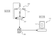
この回転ディスプレイシステムでは、図6に示すように、撮影系20において、対象物
を周囲に配置された4台の小型カメラ21によって撮影し、その撮影画像を画像合成器2
2によって合成した後に制御用PC30に送り、所定の画像処理を行う。その後、この画
像処理された合成画像を基に、複数の表示方位に応じた複数の表示画像を形成し、これら
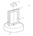
の各表示画像を図7に示す画像表示装置10に順次送出し、支持台12上において自転軸
11Xの周りを高速に自転する表示体11の自転角度に応じてその表示面11G上に表示
画像を表示するようになっている。
In this rotating display system, as shown in FIG. 6, in an
2 and then sent to the
一方、画像投影装置及びスクリーンを高速に体積走査しながら、画像投影装置からスク
リーンに対象物の断面画像を順次投影することにより、視覚の残像効果を利用して立体画
像を表示するように構成された立体画像表示装置も知られている(例えば、以下の特許文
献1参照)。
ところで、上記の回転ディスプレイシステムにおいては表示面を自転させながら表示を
行っているが、その表示面は自転軸と平行でしかも平面状に構成されているので、画像の
奥行き感が得られ難く、立体感や臨場感が不十分であるという問題があった。
By the way, in the above rotating display system, display is performed while rotating the display surface, but since the display surface is configured in parallel with the rotation axis and in a planar shape, it is difficult to obtain a sense of depth of the image. There was a problem that the three-dimensional effect and the sense of reality were insufficient.
一方、上記のスクリーンを用いた画像表示装置では、スクリーンを体積走査することに
より立体画像を表示するように構成したものであるが、図5に示す画像表示装置10と同
様にスクリーンを自転させた場合には、上記と同様に表示面が自転軸と平行でしかも平面
状に構成されていることになる。また、対象物の断面画像をスクリーンの体積走査の態様
(例えば回転角度)に応じて複雑に加工して投影しなければならないため、投影画像の処
理が複雑になるという問題点がある。さらに、このような断面画像を投影する方法では、
視認される画像が対象物の透視画像となるので、画像の明瞭性を高めることが難しいとい
う問題点がある。
On the other hand, the image display device using the screen is configured to display a stereoscopic image by volume scanning the screen, but the screen is rotated in the same manner as the
Since the visually recognized image becomes a perspective image of the object, there is a problem that it is difficult to improve the clarity of the image.
そこで本発明は上記問題点を解決するものであり、その目的は、従来よりも高い立体感
や臨場感を有する画像を形成することのできる画像表示装置を提供することにある。また
、他の目的は、従来よりも簡単な画像処理で足り、しかも、従来よりも明瞭な立体的画像
を表示できる画像表示装置を提供することにある。
Accordingly, the present invention solves the above-described problems, and an object of the present invention is to provide an image display apparatus capable of forming an image having a higher stereoscopic effect and realism than before. Another object of the present invention is to provide an image display device that can display a stereoscopic image that is clearer than the conventional image processing and that requires simple image processing.
本発明の画像表示装置は、画像を表示する表示面を有する表示体と、該表示体を自転さ
せる自転駆動手段とを有する画像表示装置において、前記表示体の外面には相互に異なる
方位を向いた複数の表示面が設けられ、前記複数の表示面には、前記表示体の自転軸に対
する法線ベクトルの角度差が相互に異なる表示面(すなわち2以上の表示面)が含まれる
ことを特徴とする。
An image display device of the present invention is an image display device having a display body having a display surface for displaying an image and rotation driving means for rotating the display body. A plurality of display surfaces, and the plurality of display surfaces include display surfaces (that is, two or more display surfaces) having different normal vector angle differences with respect to the rotation axis of the display body. And
この発明によれば、表示体の自転軸に対する法線ベクトルの角度差が相互に異なる表示
面が設けられている、換言すれば、複数の表示面のうちの或る表示面の面方位と他の表示
面の面方位とが自転軸に対して異なる角度差を有することから、表示体を回転軸線の周り
に回転させ、当該表示面に所定の画像を表示させた場合に、自転軸の周りの半径方向の画
像位置に奥行きを持たせることができるので、特に自転軸に対して斜め方向から見た画像
の立体感や臨場感を高めることができる。また、複数の表示面に対しては、各表示面の面
方位に応じた画像を表示させれば足りるので、従来のように断面画像を表示面の位置や姿
勢に合わせて表示するといったことが不要になり、複雑な画像処理が不要になるとともに
、画像の明瞭性を高めることができる。
According to the present invention, the display surfaces having different normal vector angle differences with respect to the rotation axis of the display body are provided, in other words, the surface orientation of a certain display surface among the plurality of display surfaces, and the like. Since the surface orientation of the display surface has a different angle difference with respect to the rotation axis, when the display body is rotated around the rotation axis and a predetermined image is displayed on the display surface, the display surface is rotated around the rotation axis. Since the depth of the image position in the radial direction can be increased, it is possible to enhance the stereoscopic effect and the realistic sensation of the image viewed from an oblique direction with respect to the rotation axis. In addition, since it is sufficient to display an image corresponding to the surface orientation of each display surface for a plurality of display surfaces, a cross-sectional image is displayed according to the position and orientation of the display surface as in the past. This eliminates the need for complicated image processing and improves image clarity.
ここで、上記の法線ベクトルは、表示面の面方位を示すベクトルであり、例えば、表示
面が平坦面であれば、表示面に対して直交する向きを有するベクトルである。また、表示
面が曲面である場合には、上記の法線ベクトルは表示面上のすべての点に対する法線ベク
トルの和ベクトルの方位を有するものとする。
Here, the normal vector is a vector indicating the surface orientation of the display surface. For example, if the display surface is a flat surface, the normal vector is a vector having a direction orthogonal to the display surface. Further, when the display surface is a curved surface, the above normal vector has the direction of the sum vector of the normal vectors for all points on the display surface.
本発明において、前記複数の表示面の中に、前記自転軸から離間した表示面を含むこと
が好ましい。これによれば、自転軸から離間した表示面は、表示体が自転することにより
自転軸から離間した位置を回転(公転)するので、表示面に所定の画像を表示させたとき
に当該画像によって立体形状を表現しやすくなることから、画像の立体感や臨場感をさら
に高めることができる。
In the present invention, it is preferable that a display surface separated from the rotation axis is included in the plurality of display surfaces. According to this, since the display surface separated from the rotation axis rotates (revolves) the position separated from the rotation axis by the rotation of the display body, the predetermined image is displayed on the display surface by the image. Since the three-dimensional shape can be easily expressed, it is possible to further enhance the three-dimensional effect and the realism of the image.
本発明において、前記表示体は多面体形状を有し、前記複数の表示面は、前記多面体形
状を構成する複数の面上に各々構成されていることが好ましい。これによれば、表示体の
多面体形状を構成する複数の面にそれぞれ表示面が構成されることにより、これらの複数
の表示面によって立体形状を表現しやすくなることから、画像の立体感や臨場感をさらに
高めることができる。なお、この場合、多面体形状の全ての面上に表示面が形成されてい
る必要はなく、多面体形状を構成する面のうちの少なくとも複数の面上に表示面が形成さ
れていればよい。例えば、6面体を構成する6つの面のうち、5つの面上にそれぞれ表示
面が形成され、残り一つの面上には表示面が形成されていなくてもよい。
In the present invention, it is preferable that the display body has a polyhedral shape, and the plurality of display surfaces are respectively configured on a plurality of surfaces constituting the polyhedral shape. According to this, since the display surface is configured on each of the plurality of surfaces constituting the polyhedron shape of the display body, the three-dimensional shape can be easily expressed by the plurality of display surfaces. The feeling can be further enhanced. In this case, the display surfaces do not have to be formed on all surfaces of the polyhedron shape, and the display surfaces may be formed on at least a plurality of surfaces constituting the polyhedron shape. For example, display surfaces may not be formed on five remaining surfaces, and display surfaces may be formed on the other one of six surfaces constituting a hexahedron.
本発明において、前記表示体は前記自転軸を軸線とする角柱形状を有し、前記複数の表
示面として、前記角柱形状の前記自転軸の延長方向の端面上に形成された表示面と、前記
角柱形状の側面上に形成された表示面とを有することが好ましい。これによれば、表示体
の角柱形状の側面だけでなく、自転軸の延長方向にある端面上にも表示面が形成されてい
ることにより、その端面上の表示面によって表示される画像によって奥行き感のある画像
を形成することが可能になる。
In the present invention, the display body has a prismatic shape with the rotation axis as an axis, and the display surfaces are formed on end surfaces in the extension direction of the rotation axis of the prismatic shape as the plurality of display surfaces, It is preferable to have a display surface formed on a side surface of a prismatic shape. According to this, since the display surface is formed not only on the prismatic side surface of the display body but also on the end surface in the extending direction of the rotation axis, the depth is determined by the image displayed on the display surface on the end surface. An image having a feeling can be formed.
本発明において、前記自転軸は、前記多面体形状の頂点若しくは稜線を通過するように
構成されていることが好ましい。これによれば、自転軸が多面体形状の頂点若しくは稜線
を通過することにより、表示体の支持部材や軸支構造によって表示面に対する視野が制限
されるといったことを防止できる。ここで、自転軸は表示体の外面上の2以上の点を通過
することになるので、一つの点では自転軸が多面体形状の頂点若しくは稜線を通過するが
、他の点では自転軸が多面体形状の頂点若しくは稜線以外の部位を通過するように構成さ
れていてもよい。ただし、このときの他の点は、表示面が設けられていない部分に配置さ
れていることが好ましい。また、表示体の外面上において自転軸が通過する全ての点が多
面体形状の頂点若しくは稜線であることが望ましい。
In this invention, it is preferable that the said rotating shaft is comprised so that the vertex or ridgeline of the said polyhedral shape may be passed. According to this, it can prevent that the visual field with respect to a display surface is restrict | limited by the support member of a display body, or a shaft support structure because a rotating shaft passes the vertex or ridgeline of a polyhedron shape. Here, since the rotation axis passes through two or more points on the outer surface of the display body, the rotation axis passes through the vertex or ridge line of the polyhedron shape at one point, but the rotation axis passes through the polyhedron at other points. You may be comprised so that it may pass through parts other than the vertex or ridgeline of a shape. However, the other points at this time are preferably arranged in a portion where the display surface is not provided. In addition, it is desirable that all points through which the rotation axis passes on the outer surface of the display body are apexes or ridge lines of the polyhedral shape.
本発明において、前記表示体は3次元回転体形状を有し、前記複数の表示面は、前記3
次元回転体形状の外面を区分してなる複数の領域上に各々構成されていてもよい。この場
合において、前記3次元回転体形状は、前記自転軸を回転軸とした形状であることが好ま
しい。これによれば、表示体を自転させたときにその外面位置が時間的に変化しないので
、ぶれの少ない安定した画像を表示することができる。
In the present invention, the display body has a three-dimensional rotating body shape, and the plurality of display surfaces are the 3
You may each comprise on the several area | region formed by dividing the outer surface of a three-dimensional rotary body shape. In this case, the three-dimensional rotating body shape is preferably a shape having the rotation axis as a rotation axis. According to this, since the outer surface position does not change temporally when the display body is rotated, a stable image with little blur can be displayed.
次に、添付図面を参照して本発明に係る画像表示装置の実施形態について説明する。 Next, an embodiment of an image display device according to the present invention will be described with reference to the accompanying drawings.
[第1実施形態]
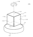
図1は本発明に係る第1実施形態の画像表示装置100の全体構成を示す概略斜視図で
ある。この画像表示装置100は、表示体110と、この表示体110を支持する支持台
120と、画像投影手段130とを有する。
[First embodiment]
FIG. 1 is a schematic perspective view showing the overall configuration of an
表示体110は多面体形状を有し、その外面上に複数の表示面110P,110S,1
10T,110U,110Vがそれぞれ設けられている。各表示面は、上記多面体形状の
各面上にそれぞれ形成されている。この表示体110は支軸114を介して支持台120
の回転板121に接続固定されている。
The
10T, 110U, and 110V are provided, respectively. Each display surface is formed on each surface of the polyhedral shape. The
It is connected and fixed to the
支持台120においては、回転板121が回転可能に構成され、支持台120内に配置
された図示しない回転駆動手段(電動モータや輪列など)によって回転駆動されるように
構成されている。したがって、回転板121が回転すると、表示体110は回転軸線11
0Xを中心に自転するようになっている。
In the support base 120, the
It is designed to rotate around 0X.
具体的には、表示体110は自転軸110Xを中心とする多角柱形状である直方体(立
方体)形状を有し、その自転軸の延長方向の端面である上面に表示面110Pが形成され
、その自転軸周りの複数の側面にそれぞれ表示面110S,110T,110U,110
Vが形成されている。また、本実施形態において、各表示面は平坦面となっている。
Specifically, the
V is formed. In the present embodiment, each display surface is a flat surface.
本実施形態では、表示面110Pは、自転軸110Xの延長方向に法線ベクトルの成分
を有する。すなわち、表示面110Pの法線ベクトルは、自転軸110Xの延長方向のベ
クトル成分を有している。特に、平坦面である表示面110Pは、自転軸110Xと非平
行である。より具体的には、表示面110Pは自転軸110Xと直交する面であり、しか
も、自転軸110Xがその中心部を通過している。したがって、表示面110Pの法線が
自転軸110Xと一致している。
In the present embodiment, the
一方、表示面110S,110T,110U,110Vはいずれも自転軸110Xから
離反している。また、表示面110S,110T,110U,110Vはいずれも自転軸
110Xと平行な面であり、その法線ベクトルは、自転軸110Xの延長方向の成分を持
たない。したがって、表示面110Pの法線ベクトルと自転軸110Xとの間の角度差(
図示例では0度)は、表示面110S,110T,110U,110Vの法線ベクトルと
自転軸110Xとの間の角度差(図示例では90度)と異なる。
On the other hand, the display surfaces 110S, 110T, 110U, and 110V are all separated from the
0 degree in the illustrated example is different from the angular difference (90 degrees in the illustrated example) between the normal vector of the display surfaces 110S, 110T, 110U, and 110V and the
本実施形態においては、表示体110の内部に上記各表示面に対応する表示装置が内蔵
されている。これらの表示装置は、例えば電気光学装置であることが好ましい。この電気
光学表示装置としては薄型ディスプレイが望ましい。具体的には、液晶表示装置(LCD
:Liquid Crystal Display)、プラズマディスプレイ表示装置(PDP:Plasma Display
Panel)、エレクトロルミネッセンス表示装置(Electroluminescence)、有機エレクト
ロルミネッセンス表示装置(Organic Electroluminescence)、電気泳動ディスプレイ表
示装置、電子放出素子を用いた表示装置(Field Emission Display 及び Surface-Conduc
tion Electron-Emitter Display等)などの各種の表示装置を用いることができる。
In the present embodiment, display devices corresponding to the respective display surfaces are built in the
: Liquid Crystal Display), Plasma display device (PDP: Plasma Display)
Panel), electroluminescence display device (Electroluminescence), organic electroluminescence display device (Organic Electroluminescence), electrophoretic display display device, display device using electron-emitting devices (Field Emission Display and Surface-Conduc)
various types of display devices such as electron-emitter display) can be used.
本実施形態においては、自転軸110Xを中心として表示体110を自転させながら、
各表示面110P,110S,110T,110U,110Vにそれぞれ適宜の表示を行
うことによって、周囲にいる観察者に所定の画像を視認させることができる。例えば、図
1の正面に観察者がいる場合を想定すれば、図示のタイミング、すなわち、観察者が表示
面110P,110S,110Tに臨む角度位置にある時点で、これらの表示面110P
,110S,110Tにそれぞれの画像を表示することにより、視覚の残像効果によって
表示体110の内部に立体物が存在するように見える画像を形成することができる。
In the present embodiment, while rotating the
By performing appropriate display on each of the display surfaces 110P, 110S, 110T, 110U, and 110V, it is possible to make a predetermined image visible to an observer around. For example, assuming that there is an observer in front of FIG. 1, at the timing shown in the drawing, that is, when the observer is at an angular position facing the display surfaces 110P, 110S, 110T, these display surfaces 110P.
, 110S, and 110T, it is possible to form an image that looks like a three-dimensional object is present inside the
このとき、上記の表示面110P,110S,110Tに共に画像を表示した後に、表
示面110P,110T,110Uに共に画像を表示し、次に、表示面110P,110
U,110Vに共に画像を表示し、さらに、表示面110P,110V,110Sに共に
画像を表示し、というように、表示体110が自転軸110Xの周りを90度回転する度
に観察者が画像を視認するように構成してもよい。もちろん、画像の表示間隔は任意であ
り、例えば、表示体110が1回転する間に表示する回数は1回〜4回のいずれでもよく
、また、表示体110が複数回転する間に何回か表示を行うといった態様で動作させても
構わない。
At this time, after displaying the images on the display surfaces 110P, 110S, and 110T, the images are displayed on the display surfaces 110P, 110T, and 110U, and then the display surfaces 110P, 110T are displayed.
An image is displayed on both U and 110V, and further on the display surfaces 110P, 110V, and 110S. Thus, each time the
本実施形態においては、表示面110Pの法線ベクトルと自転軸110Xの角度差が表
示面110S,110T,110U,110Vの法線ベクトルと自転軸110Xの角度差
と異なることにより、自転軸110Xの半径方向に見た画像位置の奥行きを得ることがで
きるため、特に斜め上方から表示体110を視認する場合における画像の奥行き感を高め
ることが可能になる。また、自転軸110Xから離反した表示面110S,110T,1
10U,110Vを備えているので、これらの表示面によって立体的画像のボリューム感
を表現することができる。したがって、観察者は従来よりも立体感や臨場感のある画像を
視認することができる。
In the present embodiment, the angle difference between the normal vector of the
Since 10U and 110V are provided, the volume of a stereoscopic image can be expressed by these display surfaces. Therefore, the observer can visually recognize an image having a stereoscopic effect and a sense of reality more than before.
なお、本実施形態では、支持台120が視覚上の障害物となっているために、表示体1
10の底面には表示面が設けられていないが、この底面が外部から視認可能に構成される
のであれば、当該底面上にも表示面を設けることができる。また、本実施形態では、表示
体110をその底面側において片持ち支持しているが、支持部材や軸支構造などによる視
野の制限が生ずるものの、上面側にも支持構造を設けることにより、両持ち状態で表示体
を支持するように構成しても構わない。
In the present embodiment, since the support stand 120 is a visual obstacle, the display body 1
Although no display surface is provided on the bottom surface of 10, if the bottom surface is configured to be visible from the outside, a display surface can also be provided on the bottom surface. Further, in this embodiment, the
[第2実施形態]
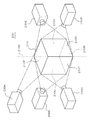
次に、図2を参照して、本発明に係る第2実施形態の画像表示装置200について説明
する。この実施形態では、表示体210が第1実施形態と同様の回転駆動手段により自転
軸210Xを中心として自転するように構成されている。本実施形態の表示体210は、
第1実施形態と同様の多面体形状(多角柱形状でもある直方体(立方体)形状)を有し、
その各面上に複数の表示面210P,210S,210T,210U,210Vを備えて
いる点で上記第1実施形態の表示体110と同様である。
[Second Embodiment]
Next, an
It has the same polyhedral shape as the first embodiment (a rectangular parallelepiped (cubic) shape that is also a polygonal column shape),
It is the same as the
本実施形態が第1実施形態と異なる点は、表示体210が自ら表示面に表示を行うので
はなく、外部に配置された画像投影手段230A,230B,230C,230D,23
0Eによって各表示面上に画像が投影されるように構成されている点にある。すなわち、
各表示面は、画像投影手段によって投影される画像を表示するスクリーン機能を有するも
のとなっている。
The present embodiment is different from the first embodiment in that the
The point is that the image is projected on each display surface by 0E. That is,
Each display surface has a screen function for displaying an image projected by the image projection means.
本実施形態においては、表示面上に画像を表示する手法が第1実施形態とは異なるもの
の、観察者から見た画像は第1実施形態と同様に構成することができる。自転軸210X
を中心として表示体210を自転させると、例えば、図2の正面に観察者がいると想定し
た場合に、図2に示すタイミング、すなわち、表示面210P,210S,210Tを観
察者が臨む時点において、それぞれの表示面210P,210S,210Tに画像投影手
段230A,230B,230Cにより所定の画像を投影すれば、観察者は第1実施形態
と同様の画像を視認できる。このとき、画像の表示間隔についても第1実施形態と同様に
任意である。
In the present embodiment, although the method for displaying an image on the display surface is different from that in the first embodiment, the image viewed from the observer can be configured in the same manner as in the first embodiment. Rotating
2, for example, when it is assumed that there is an observer in front of FIG. 2, the timing shown in FIG. 2, that is, when the observer faces the display surfaces 210 </ b> P, 210 </ b> S, 210 </ b> T. If a predetermined image is projected on the respective display surfaces 210P, 210S, and 210T by the image projection means 230A, 230B, and 230C, the observer can visually recognize the same image as in the first embodiment. At this time, the display interval of the image is also arbitrary as in the first embodiment.
本実施形態においても、上記第1実施形態と同様に、表示体210の底面上に表示面2
10Wを形成してもよい。この場合、表示面210Wに対する画像投影手段を別途設ける
ことができる。また、図2では表示体210の支持構造を省略しているが、第1実施形態
と同様に片持ち支持と両持ち支持のいずれの支持構造を有していてもよい。
Also in the present embodiment, the display surface 2 is formed on the bottom surface of the
10 W may be formed. In this case, image projection means for the
なお、本実施形態においては、表示面毎に別々の画像投影手段を設けているが、複数の
表示面に対して単一の画像投影手段によって画像を投影することも可能である。例えば、
図2に示す表示面210P,210S,210Tに図面の正面側から画像を投影すること
により、これらの複数の表示面に共に画像を表示することができる。ただし、複数の表示
面は所定の投影方向に対して相互に異なる面方位(或いは法線ベクトル)を有するので、
画像の歪が生じないように投影画像を調整しておくことが好ましい。
In the present embodiment, a separate image projecting unit is provided for each display surface. However, it is also possible to project an image on a plurality of display surfaces by a single image projecting unit. For example,
By projecting an image from the front side of the drawing onto the display surfaces 210P, 210S, and 210T shown in FIG. 2, the images can be displayed on the plurality of display surfaces. However, since the plurality of display surfaces have different plane orientations (or normal vectors) with respect to a predetermined projection direction,
It is preferable to adjust the projected image so that the image is not distorted.
[第3実施形態]
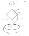
次に、図3を参照して、本発明に係る第3実施形態の画像表示装置300について説明
する。この実施形態では、表示体310は支軸314を介して支持台320に設けられた
回転板321に接続され、支持台320に内蔵された回転駆動手段により表示体310が
自転軸310Xを中心に自転するように構成されている点で、第1実施形態と同様である
。
[Third Embodiment]
Next, an
本実施形態が第1実施形態と異なる点は、表示体310の自転軸310Xが、多面体形
状を有する表示体310の頂点を通過するように設定されている点にある。表示体310
は多面体形状(より具体的には多角柱形状でもある直方体(立方体)形状)を有し、6つ
の頂点を備えている。そして、自転軸310Xは上記の頂点のうち、相互に対向配置され
た2つの頂点を通過するように構成されている。
This embodiment is different from the first embodiment in that the
Has a polyhedron shape (more specifically, a rectangular parallelepiped (cube) shape which is also a polygonal column shape) and has six apexes. The
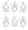
図4は、上記実施形態の画像表示装置300を動作させ、表示体310を自転させたと
きの姿勢を順次に示す概略斜視図(a)〜(f)である。ここで、表示体310の外面上
には複数の表示面310G,310H,310I,310J,310K,310Lが設け
られている。これらの表示面は、多面体形状の表示体310の複数の面上にそれぞれ形成
されている。図4(a)〜(f)は、表示体310が自転軸310Xの周りを60度ずつ
回転したときの姿勢を示している。
FIG. 4 is a schematic perspective view (a) to (f) sequentially illustrating postures when the
本実施形態では、上記の表示面310G,310H,310I,310J,310K,
310Lは、いずれも自転軸310Xの延長方向に法線ベクトルの成分を有する面となっ
ている。しかし、表示面310G,310I,310Kの法線ベクトルと自転軸310X
との間の角度差(図示例では135度)は、表示面310H,310J,310Lの法線
ベクトルと自転軸310Xとの間の角度差(図示例では45度)と異なっている。
In the present embodiment, the display surfaces 310G, 310H, 310I, 310J, 310K,
310L is a surface having a normal vector component in the extending direction of the
Is different from the angle difference between the normal vector of the display surfaces 310H, 310J, and 310L and the
ここで、図4の正面に観察者がいると想定した場合、表示体310が図4(a)〜(f
)のうちの少なくともいずれか一つの姿勢にある時点で、正面に臨む3つの表示面に共に
画像を表示することにより、立体感や臨場感のある画像を観察者が視認できるように構成
できる。ここで、観察者が視認する表示面の位置及び姿勢は120度間隔で同一になるの
で、120度間隔で表示を行うことも可能である。また、観察者が視認する表示面の位置
及び姿勢は60度間隔で変化するので、相互に異なる位置及び姿勢にある表示面状態にお
いて共に表示を行うことにより、異なる態様の表示を重ね合わせるようにして画像を形成
することもできる。これによって画像の立体感をさらに高めることも可能である。
Here, when it is assumed that there is an observer in front of FIG. 4, the
), The image is displayed on the three display surfaces facing the front at the time of being in at least one of the postures so that the viewer can visually recognize an image having a stereoscopic effect or a sense of presence. Here, since the position and orientation of the display surface visually recognized by the observer are the same at intervals of 120 degrees, it is also possible to perform display at intervals of 120 degrees. In addition, since the position and orientation of the display surface visually recognized by the observer change at intervals of 60 degrees, display in different modes is performed by superimposing the display surfaces in different display surface states at different positions and orientations. An image can also be formed. This can further enhance the stereoscopic effect of the image.
また、上記実施形態では、自転軸310Xが多面体形状の頂点を通過するように構成さ
れているので、図示しない支持部材や軸支構造を表示体310に設ける場合、これらの支
持部材や軸支構造によって表示面上の画像の一部が隠されるといったことを防止できる。
ここで、自転軸310Xは多面体形状の稜線を通過するように構成されていてもよい。こ
の場合にも、表示面上の画像の一部が支持部材や軸支構造によって隠されるといったこと
を防止することができる。さらに、自転軸310は、通常、表示体310の外面上の2点
を通過するが、本実施形態のように2点のいずれもが上記頂点若しくは稜線上にあること
が好ましいが、2点のうちの1点が頂点若しくは稜線上にあり、他の1点が頂点若しくは
稜線以外の部分にあっても構わない。この場合、上記他の1点が存在する部分には表示面
が設けられていないことが好ましい。
In the above embodiment, since the
Here, the
なお、本実施形態においても、第2実施形態と同様に画像投影手段を設けて表示面に画
像を投影することによって表示を行うように構成することができる。この場合、具体的な
構成については第2実施形態において述べたところと全く同様である。
Note that the present embodiment can also be configured to display by projecting an image on a display surface by providing an image projecting unit as in the second embodiment. In this case, the specific configuration is exactly the same as that described in the second embodiment.
[第4実施形態]
次に、図5を参照して本発明に係る第4実施形態の画像表示装置400について説明す
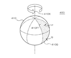
る。この実施形態は、図5に示す表示体410を有する。ここで、表示体410が自転軸
410Xを中心に自転するように構成されている点は、上記各実施形態と同様である。図
5において回転駆動手段は省略してある。
[Fourth Embodiment]
Next, an
表示体410は球形状を有し、その外面に複数の表示面410P,410Qが形成され
ている。図中において、表示面410P,410Qは図示二点鎖線で分割された球面の一
部である。本実施形態において、表示面410P,410Qは、第1実施形態のように表
示装置によって構成される表示画面であってもよく、また、第2実施形態のように別途設
けられた画像投影手段によって画像が投影されるスクリーン面であってもよい。
The
本実施形態の場合、表示面410P,410Qは、自転軸410Xの延長方向に法線ベ
クトルの成分を有する面となっている。なお、この表示面410P,410Qは曲面であ
るが、このときの法線ベクトルは、本明細書において、表示面410P,410Q上の全
ての点における法線ベクトルの和ベクトルの方位を有するものとする。ここで、表示面4
10Pは自転軸410Xの延長方向に沿った一方の側(図示上側)にある複数の表示面で
あり、表示面410Qは自転軸410Xの延長方向に沿った他方の側(図示下側)にある
複数の表示面である。
In the present embodiment, the display surfaces 410P and 410Q are surfaces having a normal vector component in the extension direction of the
10P is a plurality of display surfaces on one side (upper side in the drawing) along the extending direction of the
本実施形態では、表示面410Pの法線ベクトルPと自転軸410Xとの角度差(図示
例では45度)は、表示面410Qの法線ベクトルQと自転軸410Xとの角度差(図示
例では135度)と異なる。したがって、これらの表示面410P,410Qに画像を表
示させることで、自転軸410Xの半径方向に画像位置の奥行きを持たせることができる
ので、特に自転軸410Xに対して斜めの視線方向から観察する場合に、立体感や臨場感
のある画像を視認できるようになる。また、表示面410P,410Qは、自転軸410
Xから離間した位置に設けられているので、表示のボリューム感を出すことができること
から、画像の立体感や臨場感をさらに高めることが可能になっている。すなわち、表示体
410に対して所定の方位にいる観察者に対して、当該観察者に臨む複数の表示面410
P、410Qにそれぞれ所定の画像を表示させることで、立体感や臨場感の高い画像を提
供することが可能になる。
In the present embodiment, the angle difference between the normal vector P of the
Since it is provided at a position away from X, it is possible to give a sense of volume to the display, so that it is possible to further enhance the stereoscopic effect and presence of the image. That is, with respect to an observer who is in a predetermined orientation with respect to the
By displaying a predetermined image on each of P and 410Q, it is possible to provide an image with a high degree of stereoscopic effect and presence.
また、上記の表示体410は、自転軸410Xが中心点を通過する球形状となるように
構成されているので、表示体410が自転してもその外面位置が時間的に変動しないこと
から、外面位置の変化により表示画像にぶれが生ずるといったことを防止できる。
In addition, since the
なお、本実施形態において、上記表示体410は球形状を有するが、例えば、回転楕円
体などの3次元回転体形状(所定の断面形状を回転軸の周りに回転させて得られる立体形
状)を有していてもよい。また、上記自転軸410Xは表示体410の中心を通過し、表
示体410の外面位置が時間的に変化しないように構成されているが、本発明においては
、自転軸410が表示体410の中心を通過しないように構成されていても構わない。
In the present embodiment, the
なお、上記各実施形態では、例えば自転軸に対して斜め方向から観察者が表示体を見た
ときに、その視界には必ず、法線ベクトルと自転軸の角度差が相互に異なる複数の表示面
が同時に含まれるように構成されている。しかし、本発明はこのような態様で表示体に複
数の表示面が形成されている場合に限定されるものではない。例えば、一の表示面と自転
軸の角度差が他の表示面と自転軸の角度差と異なる場合において、表示体が自転している
ときの或る時点では観察者の視界に一の表示面が入り、他の表示面は入らないが、別の時
点では、観察者の視界に他の表示面が入り、一の表示面は入らないように構成されていて
もよい。このように構成されていても、それぞれの表示面が観察者の視界に入ったときに
各々表示を行うようにしておけば、表示体が自転することによって視覚の残像効果により
上記実施形態と同様の外観が得られるからである。
In each of the above embodiments, for example, when an observer views the display body from an oblique direction with respect to the rotation axis, the visual field always includes a plurality of displays in which the angular difference between the normal vector and the rotation axis is different from each other. It is comprised so that a surface may be included simultaneously. However, the present invention is not limited to the case where a plurality of display surfaces are formed on the display body in such a manner. For example, when the angle difference between one display surface and the rotation axis is different from the angle difference between the other display surface and the rotation axis, the one display surface is in the viewer's field of view at some point when the display body is rotating. However, at another point in time, another display surface may enter the viewer's field of view, and one display surface may not enter. Even if it is configured in this way, if each display surface is displayed when it enters the viewer's field of view, the display body rotates and the visual afterimage effect causes the same as in the above embodiment. It is because the external appearance is obtained.
100,200,300,400…画像表示装置、110,210,310,410…表
示体、110P,110S,110T,110U,110V…表示面、110X…回転軸
線、114…支軸、120…支持台、121…回転板、230A〜230E…画像投影手
段
DESCRIPTION OF SYMBOLS 100,200,300,400 ... Image display apparatus, 110,210,310,410 ... Display body, 110P, 110S, 110T, 110U, 110V ... Display surface, 110X ... Rotation axis line, 114 ... Support axis, 120 ... Support stand 121 ... Rotating plates, 230A to 230E ... Image projection means
Claims (7)
る画像表示装置において、
前記表示体の外面には相互に異なる方位を向いた複数の表示面が設けられ、
前記複数の表示面には、前記表示体の自転軸に対する法線ベクトルの角度差が相互に異
なる表示面が含まれることを特徴とする画像表示装置。 In an image display device having a display body having a display surface for displaying an image, and rotation driving means for rotating the display body,
A plurality of display surfaces facing different directions are provided on the outer surface of the display body,
The image display device according to claim 1, wherein the plurality of display surfaces include display surfaces having different normal vector angular differences with respect to the rotation axis of the display body.
る請求項1に記載の画像表示装置。 The image display apparatus according to claim 1, wherein the plurality of display surfaces include a display surface separated from the rotation axis.
の面上に各々構成されていることを特徴とする請求項1又は2に記載の画像表示装置。 The image display device according to claim 1, wherein the display body has a polyhedron shape, and the plurality of display surfaces are respectively formed on a plurality of surfaces constituting the polyhedron shape.
とを特徴とする請求項3に記載の画像表示装置。 The image display apparatus according to claim 3, wherein the rotation axis is configured to pass a vertex or a ridge line of the polyhedral shape.
角柱形状の前記自転軸の延長方向の端面上に形成された表示面と、前記角柱形状の側面上
に形成された表示面とを有することを特徴とする請求項3又は4に記載の画像表示装置。 The display body has a prismatic shape with the rotation axis as an axis, the display surfaces being formed on end surfaces in the extension direction of the rotation axis of the prismatic shape as the plurality of display surfaces, and the side surfaces of the prismatic shape. The image display apparatus according to claim 3, further comprising a display surface formed on the display surface.
外面を区分してなる複数の領域上に各々構成されていることを特徴とする請求項1又は2
に記載の画像表示装置。 The display body has a three-dimensional rotating body shape, and the plurality of display surfaces are respectively formed on a plurality of regions obtained by partitioning an outer surface of the three-dimensional rotating body shape. 1 or 2
The image display device described in 1.
項6に記載の画像表示装置。
The image display device according to claim 6, wherein the three-dimensional rotating body shape is a shape having the rotation axis as a rotation axis.
Priority Applications (1)
| Application Number | Priority Date | Filing Date | Title |
|---|---|---|---|
| JP2004109217A JP2005295326A (en) | 2004-04-01 | 2004-04-01 | Image display device |
Applications Claiming Priority (1)
| Application Number | Priority Date | Filing Date | Title |
|---|---|---|---|
| JP2004109217A JP2005295326A (en) | 2004-04-01 | 2004-04-01 | Image display device |
Publications (1)
| Publication Number | Publication Date |
|---|---|
| JP2005295326A true JP2005295326A (en) | 2005-10-20 |
Family
ID=35327751
Family Applications (1)
| Application Number | Title | Priority Date | Filing Date |
|---|---|---|---|
| JP2004109217A Withdrawn JP2005295326A (en) | 2004-04-01 | 2004-04-01 | Image display device |
Country Status (1)
| Country | Link |
|---|---|
| JP (1) | JP2005295326A (en) |
Cited By (4)
| Publication number | Priority date | Publication date | Assignee | Title |
|---|---|---|---|---|
| JP2009008837A (en) * | 2007-06-27 | 2009-01-15 | National Institute Of Information & Communication Technology | 3D display |
| JP2010247766A (en) * | 2009-04-20 | 2010-11-04 | Ihi Corp | Display device for autonomous vehicle motion monitor |
| JP5892278B1 (en) * | 2015-03-18 | 2016-03-23 | 株式会社安川電機 | Screen device, image display system, and image display method |
| KR20200130024A (en) * | 2019-05-10 | 2020-11-18 | (주)엑스오비스 | Method and device for controlling arrangement states of three dimensional units |
-
2004
- 2004-04-01 JP JP2004109217A patent/JP2005295326A/en not_active Withdrawn
Cited By (8)
| Publication number | Priority date | Publication date | Assignee | Title |
|---|---|---|---|---|
| JP2009008837A (en) * | 2007-06-27 | 2009-01-15 | National Institute Of Information & Communication Technology | 3D display |
| JP2010247766A (en) * | 2009-04-20 | 2010-11-04 | Ihi Corp | Display device for autonomous vehicle motion monitor |
| JP5892278B1 (en) * | 2015-03-18 | 2016-03-23 | 株式会社安川電機 | Screen device, image display system, and image display method |
| CN105991985A (en) * | 2015-03-18 | 2016-10-05 | 株式会社安川电机 | Screen device, image display system, and image display method |
| KR101732306B1 (en) * | 2015-03-18 | 2017-05-02 | 가부시키가이샤 야스카와덴키 | Screen device, image display system, and image display method |
| US10031408B2 (en) | 2015-03-18 | 2018-07-24 | Kabushiki Kaisha Yaskawa Denki | Screen device, image display system, and image display method for displaying an image with a screen part having at least one polyhedron |
| KR20200130024A (en) * | 2019-05-10 | 2020-11-18 | (주)엑스오비스 | Method and device for controlling arrangement states of three dimensional units |
| KR102195539B1 (en) | 2019-05-10 | 2020-12-29 | (주)엑스오비스 | Method and device for controlling arrangement states of three dimensional units |
Similar Documents
| Publication | Publication Date | Title |
|---|---|---|
| KR101365218B1 (en) | 3-Dimensional Image Display Device And Displaying Method Using The Same | |
| US6910971B2 (en) | Acceleration simulator | |
| US10607403B2 (en) | Shadows for inserted content | |
| JP2008224748A (en) | 3D image display device | |
| JP2005221946A (en) | Driving method of rotary display device | |
| JP2002073003A (en) | Stereoscopic image generation device and information storage medium | |
| JP2005295326A (en) | Image display device | |
| JP2005308980A (en) | Rotary display device | |
| Ardouin et al. | Navigating in virtual environments with 360 omnidirectional rendering | |
| CN110737105B (en) | Three-dimensional image display system | |
| JP2008281659A (en) | Display device and game device | |
| JP2018084629A (en) | Image display device | |
| US20060214874A1 (en) | System and method for an interactive volumentric display | |
| US10293246B2 (en) | Structures and kits for displaying two-dimensional images in three dimensions | |
| EP1170961A1 (en) | Three-dimensional image display | |
| WO2005024756A1 (en) | Molecular studio for virtual protein lab | |
| JP2005295325A (en) | Image display device | |
| US12192438B2 (en) | Rotating stereoscopic display device and display control method | |
| KR100913022B1 (en) | Stereoscopic Display Device and Operation Method | |
| KR20090011316A (en) | Active stereoscopic display device and operation method | |
| JP3236449U (en) | Teaching materials for learning molecular structure | |
| KR20090027009A (en) | Stereoscopic display device and its operation method | |
| JP4198713B2 (en) | Product package with images to form body images | |
| JP2017116893A (en) | Stereo image display device | |
| JP7768523B1 (en) | A program for aerial image display devices that display 360-degree images |
Legal Events
| Date | Code | Title | Description |
|---|---|---|---|
| A300 | Withdrawal of application because of no request for examination |
Free format text: JAPANESE INTERMEDIATE CODE: A300 Effective date: 20070605 |