JP2005295313A - Code reader, electronic device, parameter adjustment method, and parameter adjustment program - Google Patents
Code reader, electronic device, parameter adjustment method, and parameter adjustment program Download PDFInfo
- Publication number
- JP2005295313A JP2005295313A JP2004109058A JP2004109058A JP2005295313A JP 2005295313 A JP2005295313 A JP 2005295313A JP 2004109058 A JP2004109058 A JP 2004109058A JP 2004109058 A JP2004109058 A JP 2004109058A JP 2005295313 A JP2005295313 A JP 2005295313A
- Authority
- JP
- Japan
- Prior art keywords
- area
- brightness
- initial
- exposure
- parameter
- Prior art date
- Legal status (The legal status is an assumption and is not a legal conclusion. Google has not performed a legal analysis and makes no representation as to the accuracy of the status listed.)
- Pending
Links
Images


Landscapes
- Exposure Control For Cameras (AREA)
- Studio Devices (AREA)
Abstract
【課題】 取り込まれた画像内の測光エリアが該画像内の媒体に対応する領域からはみ出しにくいコード読取装置、電子機器、パラメータの調整方法及びパラメータ調整プログラムを提供する。
【解決手段】 カメラ付き携帯端末10は、画像に含まれる図形コードを解読する図形コード解読部13、撮像部11のデジタル画像の明るさに関係するパラメータを調整する露出制御部15とを備え、露出制御部15は、測光エリアとして初期測光用の初期エリアを設定し、該初期エリアの明るさに基づいて撮像部11の露出に関係するパラメータを調整すると共にその結果を判定し、該判定結果に従って初期エリアを測光エリアとして採用する、又は、初期エリアの大きさを変更した測光用の第2のエリアを設定し、該第2のエリアの明るさに基づいて撮像部11の露出に関係するパラメータを調整すると共にその結果を判定する制御を繰り返し実行する。
【選択図】 図3PROBLEM TO BE SOLVED: To provide a code reader, an electronic device, a parameter adjustment method, and a parameter adjustment program in which a photometric area in a captured image is difficult to protrude from an area corresponding to a medium in the image.
A camera-equipped mobile terminal includes a graphic code decoding unit that decodes a graphic code included in an image, and an exposure control unit that adjusts a parameter related to the brightness of the digital image of the imaging unit. The exposure control unit 15 sets an initial area for initial photometry as a photometric area, adjusts parameters related to exposure of the imaging unit 11 based on the brightness of the initial area, determines the result, and determines the determination result. In accordance with the above, the initial area is adopted as the photometric area, or a second area for photometry in which the size of the initial area is changed is set, and the exposure of the imaging unit 11 is related to the brightness of the second area. The control for adjusting the parameter and determining the result is repeatedly executed.
[Selection] Figure 3
Description
本発明は、2次元コード等の図形データを読み取るコード読取装置、電子機器、パラメータの調整方法及びパラメータ調整プログラムに関する。 The present invention relates to a code reader that reads graphic data such as a two-dimensional code, an electronic device, a parameter adjustment method, and a parameter adjustment program.
近年、小型で、低消費電力のイメージセンサが開発されたことに伴い、PDA(Personal Digital Assistants)や携帯電話機などの携帯端末にカメラを内蔵することが可能となり、内蔵カメラにより人物や風景を撮影したり、内蔵カメラにより撮影した画像を電子メールで即座に送信できることが可能となっている。これらの内蔵カメラは、小型であることが優先され、一般的なデジタルカメラよりも解像度が低い。 In recent years, along with the development of small, low power consumption image sensors, it has become possible to incorporate a camera in a portable terminal such as a PDA (Personal Digital Assistants) or a cellular phone, and take pictures of people and landscapes with the built-in camera. Or an image taken by the built-in camera can be sent immediately by e-mail. These built-in cameras are prioritized to be small, and have a lower resolution than general digital cameras.
カメラ付き携帯端末には、2次元コードなどの図形コードを読み取って解読する機能を有するものがある。内蔵カメラにより入力したバーコード画像に対してバーコードを認識できれば、別途バーコードリーダを用意しなくても、各種サービスを利用することができる。 Some portable terminals with a camera have a function of reading and decoding a graphic code such as a two-dimensional code. If the barcode can be recognized for the barcode image input by the built-in camera, various services can be used without preparing a separate barcode reader.
バーコードや2次元コードを2次元画像検出手段にて2次元的な画像データとして検出し、その画像データを一時的に記憶した画像データメモリ上を走査してコード読み取りを行う手法が従来から考えられている。しかし、この手法は画像中のどこに2次元コードが存在するのかわからないため画像データ全て、もしくは所定の間隔で全画像領域を操作する必要があり、時間がかかる。 Conventionally considered is a method of reading a code by scanning a bar code or a two-dimensional code as two-dimensional image data by a two-dimensional image detection means and scanning the image data memory in which the image data is temporarily stored. It has been. However, since this method does not know where the two-dimensional code exists in the image, it is necessary to operate all the image data or the entire image area at a predetermined interval, which takes time.
この課題を解決する手段として、画像中に存在する2次元コードの領域を抽出する方法が提案されている。 As a means for solving this problem, a method for extracting a region of a two-dimensional code existing in an image has been proposed.
例えば、特許文献1には、走査を画像中の同じ方向からでなく、反対方向からも交互に行っているため、画像中の幅全てを走査する必要がなく、時間の短縮を図っている。また、走査中に画素値の変化点を検出すると一定幅の直線を検出し、2次元コードの特徴であるL字型を検出する。これにより2次元コードの存在領域を絞り込んでいる。 For example, in Patent Document 1, since scanning is alternately performed not from the same direction in the image but also from the opposite direction, it is not necessary to scan all the widths in the image, and the time is reduced. Further, when a change point of the pixel value is detected during scanning, a straight line having a certain width is detected, and an L-shaped characteristic of the two-dimensional code is detected. Thereby, the existence area of the two-dimensional code is narrowed down.
また、特許文献2には、画像データを一定の小さいブロックに分割し、各ブロックの中で簡単に走査してその複雑度を算出している。複雑度とは、しきい値以上の階調差を検出した回数のことを示し、一般的に2次元コードの存在確率が高いブロックほど複雑度は増す。その観点から複雑度の高い順に各ブロックを走査して2次元コードを読み取っている。
このような従来のカメラ付き携帯端末は、シャッタースピードやゲイン、絞り値などのパラメータを変化させて取り込まれるデジタル画像の明るさを調整する機能をもっている。一般的に、カメラ付き携帯端末は取り込まれたデジタル画像内の測光エリアと呼ばれる領域の輝度指標値と目標値を比較して、目標値に近づくように上記パラメータを変更することにより好適な明るさのデジタル画像を取り込むことができる。 Such a conventional mobile terminal with a camera has a function of adjusting the brightness of a digital image captured by changing parameters such as a shutter speed, a gain, and an aperture value. Generally, a portable terminal with a camera compares the brightness index value of a region called a photometric area in a captured digital image with a target value, and changes the parameter so as to approach the target value. Digital images can be captured.
露出の制御で重要となる測光エリアは、固定である場合の他、ユーザによって変更可能、又は、デジタルカメラ自身がデジタル画像を評価して決定する場合もある。 The photometric area that is important for exposure control may be fixed by the user, or may be changed by the user, or the digital camera itself may evaluate and determine the digital image.
カメラ付き携帯端末により読み取られる図形コードは、主に名刺などの紙製の媒体に印刷されている。紙製の媒体はサイズが有限であるため、図形コードが媒体の端の方に印刷されているような場合に、取り込まれたデジタル画像内の測光エリアがデジタル画像内の媒体に対応する領域からはみ出すことがある。すると、カメラの露出に関係するパラメータが、図形コードを解読するのに適さない明るさのパラメータに変更され、図形コード解読の成功率の低下を招くという問題点があった。 The graphic code read by the camera-equipped mobile terminal is mainly printed on a paper medium such as a business card. Since the paper medium is finite in size, when the graphic code is printed toward the edge of the medium, the photometric area in the captured digital image starts from the area corresponding to the medium in the digital image. May protrude. Then, the parameter related to the exposure of the camera is changed to a parameter of brightness that is not suitable for decoding the graphic code, and there is a problem that the success rate of decoding the graphic code is reduced.
例えば、デジタル画像内の媒体の外側に対応する領域の明るさが、媒体に比べて極端に暗かったりすると、測光エリアに暗い領域が含まれることになる。このような状況になると、通常、カメラ付き携帯端末は、読み取り対象となる図形コードが存在する媒体に対応する領域が明るくなるようにデジタルカメラのパラメータを変更する。 For example, if the brightness of the area corresponding to the outside of the medium in the digital image is extremely dark compared to the medium, a dark area is included in the photometry area. In such a situation, the camera-equipped mobile terminal usually changes the parameters of the digital camera so that the area corresponding to the medium on which the graphic code to be read exists is brightened.
デジタル画像内の図形コードに対応する領域は、使用できる輝度値全体よりも狭い範囲を使って表現される。図形コードを解読してデジタル情報を取り出す機能は、媒体と図形コードのシンボルとの境界を判別して分離しなければ図形コードを解読することができない。上記のように適切なパラメータに調整されないと、媒体と図形コードとの境界の判別が付きにくくなるため、一般的に解読の成功率が低下する。 The area corresponding to the graphic code in the digital image is expressed using a range narrower than the entire usable luminance value. The function of decoding the graphic code and extracting the digital information cannot decode the graphic code unless the boundary between the medium and the symbol of the graphic code is determined and separated. If the parameter is not adjusted to an appropriate parameter as described above, it is difficult to determine the boundary between the medium and the graphic code, so that the decoding success rate generally decreases.
一般に出回っているデジタルスチルカメラには、評価測光などの名前で、デジタルスチルカメラ自身が、測光エリアを取り込んだ画像を評価して変更する機能を持ったものがある。しかし、従来のアルゴリズムは風景や人物を撮影するためのもので、2次元コードのような図形コードを読み取るのに適したものではない。 Some digital still cameras on the market have a function of evaluating and changing an image in which a photometric area is taken by the digital still camera itself under a name such as evaluation photometry. However, the conventional algorithm is for photographing a landscape or a person, and is not suitable for reading a graphic code such as a two-dimensional code.
本発明は、このような課題に鑑みてなされたものであって、取り込まれた画像内の測光エリアが該画像内の媒体に対応する領域からはみ出しにくいコード読取装置、電子機器、パラメータの調整方法及びパラメータ調整プログラムを提供することを目的とする。 The present invention has been made in view of such a problem, and a photometric area in a captured image is unlikely to protrude from an area corresponding to a medium in the image. And it aims at providing a parameter adjustment program.
本発明のコード読取装置は、被写体を撮像する撮像手段と、前記撮像手段から取り込んだ画像の測光エリアの明るさに応じて、前記撮像手段の露出に関係するパラメータを調整する露出制御手段と、調整された前記パラメータを使用して、前記撮像手段により取り込まれた画像に含まれる図形コードを解読する図形コード解読手段とを備えるコード読取装置であって、前記露出制御手段は、前記測光エリアとして初期測光用の初期エリアを用いて前記撮像手段の露出に関係するパラメータを調整することを特徴としている。 The code reader of the present invention includes an imaging unit that images a subject, an exposure control unit that adjusts a parameter related to exposure of the imaging unit according to the brightness of a photometric area of an image captured from the imaging unit, A code reading device comprising a graphic code decoding means for decoding a graphic code included in an image captured by the imaging means using the adjusted parameter, wherein the exposure control means serves as the photometric area A parameter related to exposure of the image pickup means is adjusted using an initial area for initial photometry.
本発明のコード読取装置は、被写体を撮像する撮像手段と、前記撮像手段から取り込んだ画像の測光エリアの明るさに応じて、前記撮像手段の露出に関係するパラメータを調整する露出制御手段と、調整された前記パラメータを使用して、前記撮像手段により取り込まれた画像に含まれる図形コードを解読する図形コード解読手段とを備えるコード読取装置であって、前記露出制御手段は、前記測光エリアとして初期測光用の初期エリアを設定し、該初期エリアの明るさに基づいて前記撮像手段の露出に関係するパラメータを調整し、前記初期エリアの大きさを変更した測光用のn(nは1から始まる自然数)番のエリアを設定し、該n番のエリアの明るさを判定し、該明るさの判定結果に従って該n番のエリアが測光エリアとして採用可能と判定された場合は、該n番のエリアの明るさに基づいて前記撮像手段の露出に関係するパラメータを調整し、該n番のエリアの大きさを変更した測光用のn+1番のエリアを設定して、該n+1番のエリアの明るさを判定し、該n番のエリアが測光エリアとして採用不可と判定された場合は、該n番のエリアの大きさを変更した測光用のn+1番のエリアを設定しない制御を繰り返すことを特徴としている。 The code reader of the present invention includes an imaging unit that images a subject, an exposure control unit that adjusts a parameter related to exposure of the imaging unit according to the brightness of a photometric area of an image captured from the imaging unit, A code reading device comprising a graphic code decoding means for decoding a graphic code included in an image captured by the imaging means using the adjusted parameter, wherein the exposure control means serves as the photometric area An initial area for initial metering is set, a parameter related to exposure of the imaging means is adjusted based on the brightness of the initial area, and the size of the initial area is changed (n is from 1) (Natural number starting) number area is set, the brightness of the nth area is judged, and the nth area can be adopted as the photometry area according to the brightness judgment result If it is determined, a parameter related to exposure of the imaging means is adjusted based on the brightness of the nth area, and an n + 1th area for photometry is set by changing the size of the nth area. Then, the brightness of the n + 1 area is determined, and if it is determined that the nth area cannot be used as a photometry area, the n + 1 number for photometry in which the size of the nth area is changed is determined. It is characterized by repeating control without setting an area.
また、露出制御手段は、前記n番のエリアが測光エリアとして採用可能と判定された場合でも、該n番のエリアの大きさを変更した測光用のn+1番のエリアを設定しないものであってもよい。 Further, the exposure control means does not set the n + 1 area for photometry in which the size of the nth area is changed even when it is determined that the nth area can be adopted as the photometry area. Also good.
前記撮像手段の露出に関係するパラメータの調整は、調整量0の調整又は前記調整をスキップして該調整を行わないことを含むものである。 The adjustment of the parameter related to the exposure of the image pickup means includes adjustment of the adjustment amount 0 or skipping the adjustment and not performing the adjustment.
以上のように構成された本発明のコード読取装置によって、被写体である図形コードが記述された媒体のサイズが有限であるとき(例えば、媒体である紙の端付近に図形コードが印刷されているとき)、前記露出制御手段は前記画像内の明るさ検出する領域を、前記画像内で前記媒体に対応する領域内に収めるように定めることができ、前記図形コード解読手段が前記図形コードを復号し易い明るさに前記パラメータを調整することが可能になる。 When the size of the medium on which the graphic code as the subject is described is finite by the code reader of the present invention configured as described above (for example, the graphic code is printed near the edge of the paper as the medium) The exposure control means can determine a brightness detection area in the image so as to be within an area corresponding to the medium in the image, and the graphic code decoding means decodes the graphic code. It is possible to adjust the parameter to a brightness that is easy to perform.
前記測光エリアは、取り込んだ画像内の明るさを検出する領域である。 The photometric area is an area for detecting the brightness in the captured image.
前記図形コードは、2次元コード、又は、QRコードであってもよい。 The graphic code may be a two-dimensional code or a QR code.
前記パラメータは、画像の明るさに影響があるパラメータであることがより好ましい。 The parameter is more preferably a parameter that affects the brightness of the image.
前記パラメータは、シャッタースピード、露光時間、ゲイン、又は絞り値のパラメータであってもよい。 The parameter may be a shutter speed, exposure time, gain, or aperture value parameter.
より好ましい具体的な態様として、前記初期エリアは、前記取り込んだ画像の中央方向に位置するエリアである。 As a more preferable specific aspect, the initial area is an area located in the center direction of the captured image.
より好ましい具体的な態様として、前記エリアの大きさの変更は、エリアの大きさの拡大である。 As a more preferable specific aspect, the change in the size of the area is an enlargement of the size of the area.
本発明の電子機器は、2次元コードシンボルを読み込み可能な電子機器において、上記コード読取装置を備えることを特徴としている。 An electronic apparatus according to the present invention is an electronic apparatus capable of reading a two-dimensional code symbol, and includes the code reading device.
本発明のパラメータの調整方法は、撮像手段から取り込んだ画像の測光エリアの明るさに応じて、該撮像手段の露出に関係するパラメータを調整するパラメータの調整方法において、前記測光エリアとして初期測光用の初期エリアを設定するステップと、前記初期エリアの明るさに基づいて前記撮像手段の露出に関係するパラメータを調整するステップと、該初期エリアの大きさを変更した測光用のn番のエリアを設定するステップと、n番のエリアの明るさの指標を評価するステップと、前記評価結果に従って前記n番のエリアを測光エリアとして採用するか否かを判定するステップと、前記n番のエリアを採用する場合は、前記n番のエリアの明るさに基づいて前記撮像手段の露出に関係するパラメータを調整するステップ、又はこのステップを飛ばしたことを意味する空のステップと、該n番のエリアの大きさを変更した測光用のn+1番のエリアを設定するステップとを有限回繰り返し実行することを特徴としている。 The parameter adjustment method of the present invention is a parameter adjustment method for adjusting a parameter related to exposure of an imaging unit according to the brightness of the photometric area of an image captured from the imaging unit. A step of setting the initial area, a step of adjusting a parameter relating to exposure of the imaging means based on the brightness of the initial area, and an nth area for photometry in which the size of the initial area is changed A step of setting, a step of evaluating an index of brightness of the n-th area, a step of determining whether or not to adopt the n-th area as a photometric area according to the evaluation result, and the n-th area If it is adopted, a step of adjusting a parameter related to exposure of the imaging means based on the brightness of the nth area, or this step And an empty step, which means that the skip-up, is characterized by repeatedly running a finite number of times and setting the n + 1 th area of photometry you change the size of the area of the n-th.
本発明のパラメータの調整方法は、撮像手段から取り込んだ画像の測光エリアの明るさに応じて、該撮像手段の露出に関係するパラメータを調整するパラメータの調整方法において、前記測光エリアとして初期測光用の初期エリアを設定するステップと、前記初期エリアの明るさに基づいて前記撮像手段の露出に関係するパラメータを調整するステップと、前記初期エリアを拡張した測光用のn番のエリアを設定するステップと、前記n番のエリアに含まれるm個の領域を抽出するステップと、前記m個の領域のうちの任意のA領域の明るさの指標を評価するステップであり、前記初期エリアの明るさの指標と前記A領域の明るさの指標とを比較するステップと、前記比較により明るさ指標の差が所定量以上あるときは、前記A領域は明るさを検出する領域として採用せず、前記m個の領域に含まれるA領域を除く領域のそれぞれについて前記A領域と同様な評価を行うステップと、前記m個の領域に含まれるすべての領域において該採用しない判定がなされなかった場合、該n番のエリアを前記画像内の明るさを検出する領域として採用するステップとを有することを特徴としている。 The parameter adjustment method of the present invention is a parameter adjustment method for adjusting a parameter related to exposure of an imaging unit according to the brightness of the photometric area of an image captured from the imaging unit. A step of setting an initial area, a step of adjusting a parameter relating to exposure of the imaging means based on brightness of the initial area, and a step of setting an nth area for photometry that is an extension of the initial area A step of extracting m areas included in the n-th area, and a step of evaluating a brightness index of an arbitrary area A among the m areas, and the brightness of the initial area And comparing the brightness index of the A area with the brightness index of the A area, and if the difference between the brightness indices is a predetermined amount or more by the comparison, the A area is brightness The step of performing the same evaluation as the A area for each of the areas excluding the A area included in the m areas without adopting it as the area to be detected, and the adoption in all the areas included in the m areas If no determination is made, the step of adopting the n-th area as a region for detecting brightness in the image is provided.
本発明のパラメータの調整方法は、撮像手段から取り込んだ画像の測光エリアの明るさに応じて、該撮像手段の露出に関係するパラメータを調整するパラメータの調整方法において、前記測光エリアとして初期測光用の初期エリアを設定するステップと、前記初期エリアの明るさに基づいて前記撮像手段の露出に関係するパラメータを調整するステップと、前記初期エリアを拡張した測光用のn番のエリアを設定するステップと、前記n番のエリアに含まれるm個の領域を抽出するステップと、前記m個の領域のうちの任意のA領域の明るさの指標を評価するステップであり、前記初期エリアの明るさの指標と前記A領域の明るさの指標とを比較するステップと、前記比較により明るさ指標の差が所定量以上あるときは、前記A領域は明るさを検出する領域として採用せず、前記m個の領域に含まれる前記A領域を除く領域のそれぞれについて前記A領域と同様な評価を行うステップと、該n番のエリアから前記m個の領域のうち該採用しない判定がなされた領域を除いたエリアを、評価済みn番のエリアとして前記画像内の明るさを検出する領域として採用するステップとを有することを特徴としている。 The parameter adjustment method of the present invention is a parameter adjustment method for adjusting a parameter related to exposure of an imaging unit according to the brightness of the photometric area of an image captured from the imaging unit. A step of setting an initial area, a step of adjusting a parameter relating to exposure of the imaging means based on brightness of the initial area, and a step of setting an nth area for photometry that is an extension of the initial area A step of extracting m areas included in the n-th area, and a step of evaluating a brightness index of an arbitrary area A among the m areas, and the brightness of the initial area And comparing the brightness index of the A area with the brightness index of the A area, and if the difference between the brightness indices is a predetermined amount or more by the comparison, the A area is brightness The step of performing the same evaluation as that of the A area for each of the areas excluding the A area included in the m areas without being adopted as the area to be detected, and among the m areas from the nth area And adopting an area excluding the area determined not to be adopted as an area for detecting brightness in the image as an evaluated n-th area.
前記初期エリアは、前記取り込んだ画像の中央方向に位置することが好ましい。 The initial area is preferably located in the center direction of the captured image.
より好ましい具体的な態様として、前記初期エリアは、前記取り込んだ画像の中央方向に位置する矩形エリアであり、前記n番のエリアは、前記初期エリアを囲む矩形である。 As a more preferred specific mode, the initial area is a rectangular area located in the center direction of the captured image, and the n-th area is a rectangle surrounding the initial area.
より好ましい具体的な態様として、前記n番のエリアに含まれるm個の領域は、矩形の前記初期エリアの側面付近にある上下左右の4つの領域である。 As a more preferred specific mode, the m areas included in the n-th area are four areas on the top, bottom, left and right in the vicinity of the side surface of the rectangular initial area.
別の観点から、本発明は、撮像手段から取り込んだ画像の測光エリアの明るさに応じて、該撮像手段の露出に関係するパラメータを調整するパラメータの調整方法において、前記測光エリアとして初期測光用の初期エリアを設定するステップと、前記初期エリアの明るさに基づいて前記撮像手段の露出に関係するパラメータを調整するステップと、該初期エリアの大きさを変更した測光用のn番のエリアを設定するステップと、n番のエリアの明るさの指標を評価するステップと、前記評価結果に従って前記n番のエリアを測光エリアとして採用するか否かを判定するステップと、前記n番のエリアを採用する場合は、前記n番のエリアの明るさに基づいて前記撮像手段の露出に関係するパラメータを調整するステップ、又はこのステップを飛ばしたことを意味する空のステップと、該n番のエリアの大きさを変更した測光用のn+1番のエリアを設定するステップとを、コンピュータに有限回繰り返し実行させるためのプログラムである。 From another point of view, the present invention provides an initial photometric area as the photometric area in the parameter adjustment method for adjusting a parameter related to exposure of the image pickup means according to the brightness of the photometric area of the image captured from the image pickup means. A step of setting the initial area, a step of adjusting a parameter relating to exposure of the imaging means based on the brightness of the initial area, and an nth area for photometry in which the size of the initial area is changed A step of setting, a step of evaluating an index of brightness of the n-th area, a step of determining whether or not to adopt the n-th area as a photometric area according to the evaluation result, and the n-th area When adopting, the step of adjusting the parameter related to the exposure of the imaging means based on the brightness of the n-th area, or this step And an empty step, which means that it has play, and setting the n + 1 th area for photometry changing the size of the area of the n-th, which is a program for causing repeatedly executed a finite number of times to the computer.
また、本発明は、撮像手段から取り込んだ画像の測光エリアの明るさに応じて、該撮像手段の露出に関係するパラメータを調整するパラメータの調整方法において、前記測光エリアとして初期測光用のエリアを設定するステップと、前記初期エリアの明るさに基づいて前記撮像手段の露出に関係するパラメータを調整するステップと、前記初期エリアを拡張した測光用のn番のエリアを設定するステップと、前記n番のエリアに含まれるm個の領域を抽出するステップと、前記m個の領域のうちの任意のA領域の明るさの指標を評価するステップであり、前記初期エリアの明るさの指標と前記A領域の明るさの指標とを比較するステップと、前記比較により明るさ指標の差が所定量以上あるときは、前記A領域は明るさを検出する領域として採用せず、前記m個の領域に含まれるA領域を除く領域のそれぞれについて前記A領域と同様な評価を行うステップと、前記m個の領域に含まれるすべての領域において該採用しない判定がなされなかった場合、該n番のエリアを前記画像内の明るさを検出する領域として採用するステップとをコンピュータに実行させるためのプログラムである。 According to the present invention, in the parameter adjustment method for adjusting a parameter related to exposure of the imaging unit according to the brightness of the photometric area of the image captured from the imaging unit, an area for initial photometry is used as the photometric area. A step of setting, a step of adjusting a parameter related to exposure of the imaging means based on brightness of the initial area, a step of setting an nth area for photometry that is an extension of the initial area, and the n Extracting m areas included in the number area, and evaluating a brightness index of an arbitrary area A among the m areas, wherein the brightness index of the initial area and the The step of comparing the brightness index of the area A, and when the difference of the brightness index is equal to or larger than a predetermined amount by the comparison, the area A is an area for detecting brightness. The step of performing the same evaluation as that of the area A for each of the areas other than the area A included in the m areas is not used, and the determination that the area is not adopted is made in all the areas included in the m areas. If not, a program for causing the computer to execute the step of adopting the nth area as an area for detecting brightness in the image.
また、本発明は、撮像手段から取り込んだ画像の測光エリアの明るさに応じて、該撮像手段の露出に関係するパラメータを調整するパラメータの調整方法において、前記測光エリアとして初期測光用のエリアを設定するステップと、前記初期エリアの明るさに基づいて前記撮像手段の露出に関係するパラメータを調整するステップと、前記初期エリアを拡張した測光用のn番のエリアを設定するステップと、前記n番のエリアに含まれるm個の領域を抽出するステップと、前記m個の領域のうちの任意のA領域の明るさの指標を評価するステップであり、前記初期エリアの明るさの指標と前記A領域の明るさの指標とを比較するステップと、前記比較により明るさ指標の差が所定量以上あるときは、前記A領域は明るさを検出する領域として採用せず、前記m個の領域に含まれる前記A領域を除く領域のそれぞれについて前記A領域と同様な評価を行うステップと、該n番のエリアから前記m個の領域のうち該採用しない判定がなされた領域を除いたエリアを、評価済みn番のエリアとして前記画像内の明るさを検出する領域として採用するステップとをコンピュータに実行させるためのプログラムである。 According to the present invention, in the parameter adjustment method for adjusting a parameter related to exposure of the imaging unit according to the brightness of the photometric area of the image captured from the imaging unit, an area for initial photometry is used as the photometric area. A step of setting, a step of adjusting a parameter related to exposure of the imaging means based on brightness of the initial area, a step of setting an nth area for photometry that is an extension of the initial area, and the n Extracting m areas included in the number area, and evaluating a brightness index of an arbitrary area A among the m areas, wherein the brightness index of the initial area and the The step of comparing the brightness index of the area A, and when the difference of the brightness index is equal to or larger than a predetermined amount by the comparison, the area A is an area for detecting brightness. The step of performing the same evaluation as that of the area A for each of the areas other than the area A included in the m areas, and the determination not to adopt the m areas from the nth area. This is a program for causing a computer to execute the step of adopting an area excluding the area where the brightness is made as an area for detecting brightness in the image as an evaluated n-th area.
以上、詳述したように、本発明によれば、図形コードが記述された媒体のサイズが有限であるような場合でも、カメラの測光エリアが有限の媒体からはみ出しにくくすることができ、カメラの露出に関係するパラメータを、図形コードを解読するのに適した明るさの画像を取り込むパラメータに調整することができる。これにより、媒体と2次元コードのシンボルとの境界の判別が明確となり、解読の成功率を向上させることができる。 As described above in detail, according to the present invention, even when the size of the medium on which the graphic code is described is finite, the photometric area of the camera can be prevented from protruding from the finite medium. The parameter related to exposure can be adjusted to a parameter that captures an image having a brightness suitable for decoding the graphic code. This makes it possible to clearly determine the boundary between the medium and the symbol of the two-dimensional code, and improve the decoding success rate.
以下、添付図面を参照しながら本発明の好適なコード読取装置及びパラメータの調整方法の実施の形態について詳細に説明する。 DESCRIPTION OF EMBODIMENTS Hereinafter, preferred embodiments of a code reading device and a parameter adjusting method of the present invention will be described in detail with reference to the accompanying drawings.
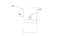
図1は、本発明の実施の形態のコード読取装置の外観を示す図である。本実施の形態は、コード読取装置を備える電子機器としてカメラ付き携帯電話機/PHS(Personal Handy-Phone System)の携帯端末に適用した例である。 FIG. 1 is a diagram showing an appearance of a code reading apparatus according to an embodiment of the present invention. This embodiment is an example in which the present invention is applied to a mobile phone with camera / PHS (Personal Handy-Phone System) as an electronic device including a code reader.
図1において、10は、カメラ付き携帯端末(コード読取装置,電子機器)であり、カメラ付き携帯端末10本体10a背面には、画像情報を撮像する撮像装置であるデジタルカメラ110(撮像手段)が搭載されている。
In FIG. 1,
デジタルカメラ110は、カメラ付き携帯端末10に内蔵された例えば100万画素のCCD(Charge Coupled Device)(エリア型固体撮像素子)カメラである。また、図示は省略するが本体10a正面には、デジタルカメラ110の入力を決定するシャッターボタン/シャッターキーが設けられている。
The
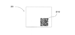
図2は、カメラ付き携帯端末10が読み取る2次元コードが印刷された紙の媒体を示す図である。
FIG. 2 is a diagram illustrating a paper medium on which a two-dimensional code read by the camera-equipped
図2において、20は2次元コード210が印刷された紙の媒体である。2次元コード210(図形コード)は、QRコードである。
In FIG. 2, 20 is a paper medium on which a two-
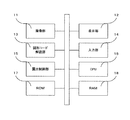
図3は、カメラ付き携帯端末10の内部構成を示すブロック図である。
FIG. 3 is a block diagram showing the internal configuration of the camera-equipped
図3において、カメラ付き携帯端末10は、デジタルカメラ110に接続されデジタル画像を取り込む撮像部11(撮像手段)、画像やテキスト情報などの情報を表示する表示部12、デジタル画像に含まれる図形コードを解読してデジタル情報を取り出す図形コード解読部13(図形コード解読手段)、ユーザに操作される機能キー,カーソルキー等からなる入力部14、撮像部11のデジタル画像の明るさに関係するパラメータを調整する露出制御を行う露出制御部15(露出制御手段)と、カメラ付き携帯端末10の各部を制御及び監視するCPU16、制御プログラムや固定データを格納するROM17、及び実行中のプログラムやデータを一時的に保存するRAM18を含んで構成される。
In FIG. 3, the camera-equipped
上記図形コード解読部13及び露出制御部15は、具体的にはCPU16の制御処理により実現される。露出制御部15による露出制御及びパラメータ調整処理については図5、図7、図9、図13により後述する。
Specifically, the graphic
図形コード解読部13は、デジタル画像を受け取り、上記デジタル画像に含まれる2次元コードを解読してデジタル情報を出力する。ここでは、受け取るデジタル画像のサイズを縦480ピクセル、横480ピクセルとするが任意のサイズを受け取ってもよい。1ピクセルはYUV色空間のY値の8ビット表現を含む。但し、1ピクセルに含まれる値は、輝度を表す値であれば他のいかなるものでもよくビット数も限定しない。
The graphic
撮像部11の撮像デバイスはCCDセンサやCMOSセンサであり、レンズを通して入ってきた光をアナログ電気信号に変換する。アナログ電気信号はA/Dコンバータによりデジタル電気信号へ変換される。一般的に、アナログ電気信号はゲインによる信号増幅回路など、数種の変換が行われる。また、デジタル電気信号についても、ガンマ特性変換回路や色空間変換回路などにより処理がなされ、好ましいデジタル画像が得られる。
The imaging device of the
露出制御部15は、デジタル画像内の複数画素の輝度値から画像の明るさを判断して、デジタル画像が目標の明るさに近づくように撮像部11のパラメータを変更する。ここで変更されるパラメータは、シャッタースピード(露光時間)、ゲイン、絞り値などの取り込まれる画像の明るさに影響があるパラメータである。評価されるデジタル画像は、上記A/Dコンバータにより変換された後の信号であればよく、評価されるタイミングは問わない。本例では、取り込むデジタル画像のサイズを縦480ピクセル、縦480ピクセルとする。上記取り込むデジタル画像のサイズは任意のサイズをとりうる。一般的に撮像部11は上記取り込むデジタル画像のサイズより大きなサイズのデジタル画像を取り込み、好ましいデジタル画像を得るために周辺部に位置するピクセルを画像処理のために用いる。
The
露出制御部15は、取り込んだデジタル画像内の領域を画像の明るさを判断するための測光エリアとして用いる。測光エリアの形状は、正方形や長方形、ひし形など、領域を指定できるものであればよく、様々な形状が考えられる。また、測光エリアのサイズについても、デジタル画像より大きくなければ任意のサイズをとることが可能であり、測光エリアのデジタル画像内の位置はデジタル画像からはみ出さない範囲で任意である。また、デジタル画像内に、測光エリアが点在するような、離散的な領域の指定も可能である。以下、上記測光エリアに含まれる画素を測光用画素と呼ぶことにする。
The
以下、上述のように構成されたカメラ付き携帯端末10のパラメータの調整方法を説明する。 Hereinafter, a parameter adjustment method of the camera-equipped mobile terminal 10 configured as described above will be described.
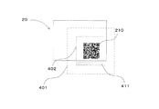
図4は、紙の媒体20に印刷された2次元コード210をカメラ付き携帯端末10で撮影したときの取り込んだデジタル画像の範囲と使用したカメラの測光エリアを示す図である。
FIG. 4 is a diagram showing a range of a captured digital image and a photometric area of the camera used when the two-
図4において、401は撮像部11が取り込んだデジタル画像領域、402はデジタル画像内の測光エリア領域を示している。この測光エリアの設定では、測光エリア402が紙の媒体20からはみ出し、はみ出し領域411(図4網掛け部分参照)が存在する。このとき、はみ出し領域411の光量が、紙の媒体20の光量よりも暗い場合、取り込まれるデジタル画像内の紙の媒体20に対応する領域の明るさは、露出制御部15の制御により、測光エリア領域が紙の媒体20内に収まっている場合よりも明るくなる。
In FIG. 4, 401 indicates a digital image area captured by the
かかる状況を回避するために、露出制御部15は以下述べるような処理を行って測光エリアを決定する。
In order to avoid such a situation, the
露出制御部15が、取り込まれるデジタル画像の明るさを目標に近づける処理について説明するが、これは一般的にデジタルスチルカメラで行われている処理であるので簡潔に述べる。
A process in which the
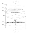
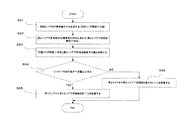
図5は、露出制御部15が取り込まれるデジタル画像の明るさを目標に近づける処理のフローチャートであり、CPU16により実行される。図中、Sはフローの各ステップである。
FIG. 5 is a flowchart of processing for bringing the brightness of the digital image captured by the
まず、ステップS51で撮像部11は撮像デバイスからデジタル画像を取り込む。次いで、ステップS52で各測光用画素の輝度値を加算して平均値を求め、これを輝度平均値と呼ぶ。ここで、輝度値はYUV色空間のY値が代表的であるが、輝度を表現するものであれば何でもよい。
First, in step S51, the
ステップS53では、輝度平均値とあらかじめ定めておいた目標輝度値と比較して、ステップS54で一定量以上大きい、又は、小さい場合は、ステップS55へ進む。輝度平均値と目標輝度値との差が一定量より小さい場合は、処理を終了する。輝度平均値が目標輝度値よりも大きい場合は、つまり取り込まれたデジタル画像が明るすぎるとされた場合は、ステップS55で撮像部11のパラメータを取り込まれるデジタル画像が暗くなる方向へ、逆の場合は、デジタル画像が明るくなる方向へ変更する。次いで、ステップS56で変更されたパラメータを使用してデジタル画像を取り込んで上記ステップS52に戻る。
In step S53, the process proceeds to step S55 if the brightness average value is larger than a predetermined amount or smaller than the predetermined target brightness value in step S54. If the difference between the average brightness value and the target brightness value is smaller than a certain amount, the process is terminated. If the average luminance value is larger than the target luminance value, that is, if the captured digital image is too bright, the reverse is the case in which the digital image into which the parameter of the
以上が、一般的にデジタルスチルカメラで行われている、取り込まれるデジタル画像の明るさを目標に近づける処理である。 The above is a process that is generally performed by a digital still camera to bring the brightness of a captured digital image closer to a target.
以下、図6乃至図15を参照して本カメラ付き携帯端末10の特徴的な動作について説明する。 Hereinafter, the characteristic operation of the camera-equipped mobile terminal 10 will be described with reference to FIGS.
本実施の形態では、露出制御部15は、測光エリアの初期エリアとして、上記取り込まれたデジタル画像内の中央位置の縦240ピクセル、横240ピクセルの領域を使用する。図4に示すように、上記サイズは撮像部11によって取り込まれたデジタル画像のサイズに対して縦、横のサイズが半分であり小さいため、紙の媒体20内に測光エリア領域402収まっている可能性が高い。なお、初期エリアのサイズは上記のサイズに限定しない。
In the present embodiment, the
露出制御部15は、上記初期エリアを測光エリアとして図5のフローを実行する。すなわち、取り込まれたデジタル画像全体に対して図5のフローを実行するのではなく、縦、横のサイズが半分で中央位置にある初期エリアを測光エリアとして図5のフローを実行するものである。これにより、取り込まれたデジタル画像内の上記初期エリアの明るさは十分目標輝度値に近づくことになる。この状態で取り込まれたデジタル画像を次の処理に用いる。このデジタル画像を処理対象デジタル画像と呼ぶことにする。
The
上記初期エリアを上下左右の4つの方向に10ピクセルずつ広げて、第2エリアを考える。広げるサイズは任意である。上記第2エリアが測光エリアの候補となるが、以下に述べる計算により採用/不採用が決定される。 Consider the second area by expanding the initial area by 10 pixels in four directions, top, bottom, left and right. The spreading size is arbitrary. The second area is a candidate for the photometry area, and adoption / non-adoption is determined by the calculation described below.
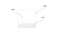
図6は、初期エリアと第2エリアと第2エリア下部領域を示す図であり、ここでは、初期エリア601と第2エリア602と第2エリア602に含まれるエリア611示している。
FIG. 6 is a diagram showing the initial area, the second area, and the lower area of the second area. Here, the
図6において、611は第2エリアに含まれるエリアであり、エリア611は、第2エリア602内の領域のうち、初期エリア601より位置的に下にある領域である。これを第2エリア下部領域と呼ぶことにする。
In FIG. 6,
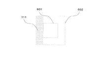
図7は、初期エリアと第2エリアと第2エリア左部領域を示す図であり、ここでは、初期エリア601と第2エリア602と第2エリア602に含まれるエリア711を示している。
FIG. 7 is a diagram showing an initial area, a second area, and a left area of the second area. Here, an
図7において、711は第2エリア602に含まれるエリアであり、エリア711は、第2エリア602内の領域のうち、初期エリア601より位置的に左にある領域である。これを第2エリア左部領域と呼ぶことにする。
In FIG. 7,
図示は省略するが同じように、第2エリア602内の領域のうち、初期エリア601より位置的に上にある領域である第2エリア上部領域と、第2エリア602内の領域のうち、初期エリア601より位置的に右にある領域である第2エリア右部領域が定められる。
Similarly, although not shown in the drawing, among the areas in the
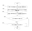
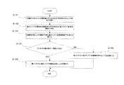
図8は、第2エリアの不採用を決定する処理を示すフローチャートである。 FIG. 8 is a flowchart showing processing for determining non-adoption of the second area.
まず、ステップS81で初期エリア601内の画素について輝度値の平均を求め、これを初期エリア輝度平均値と呼ぶ。次いで、ステップS82で第2エリア下部領域内の画素について輝度値の平均を求め、これを第2エリア下部領域輝度平均値と呼ぶ。ここで、ステップS81とステップS82はどちらが先に処理されてもよい。
First, in step S81, an average luminance value is obtained for the pixels in the
ステップS83では、初期エリア輝度平均値と第2エリア下部領域内輝度平均値を比較する。ステップS84で、二つの平均値の差がある一定量以上あった場合、ステップS85でこの第2エリアを測光エリアとして採用せず本フローを終了する。上記ある一定量は、事前に予め実験等により効果が十分発揮されるような値を定めておく。ステップS84で、二つの平均値の差が一定量に満たない場合、第2エリア内の他の領域について評価を続ける。 In step S83, the initial area luminance average value and the second area lower area luminance average value are compared. If it is determined in step S84 that the difference between the two average values is greater than or equal to a certain amount, this flow is terminated without using the second area as a photometric area in step S85. The certain amount is determined in advance such that the effect is sufficiently exhibited by experiments or the like. If the difference between the two average values is less than a certain amount in step S84, the evaluation is continued for the other areas in the second area.
第2エリア内の他の領域についての評価は、第2エリア下部領域を評価した方法と領域の位置を除くと同じである。つまり、第2エリア左部領域内の画素について輝度値の平均を求め、これを第2エリア左部領域輝度平均値と呼ぶ。初期エリア輝度平均値と第2エリア左部領域輝度平均値を比較して、二つの平均値の差がある一定量以上あった場合、第2エリアは不採用となる。上記二つの平均値の差が一定量に満たない場合、第2エリア内の他の領域について評価を続ける。同様に、第2エリア上部領域、第2エリア右部領域と評価が続けられ、以上4つの領域の評価すべてで不採用とならなかったとき、第2エリアは新しい測光エリアとして採用となる。上記4つの領域が処理される順番は任意である。 The evaluation for the other areas in the second area is the same as the method for evaluating the lower area of the second area and the position of the area. That is, the average luminance value is obtained for the pixels in the left area of the second area, and this is called the second area left area luminance average value. When the initial area luminance average value and the second area left area luminance average value are compared, and the difference between the two average values is a certain amount or more, the second area is not adopted. If the difference between the two average values is less than a certain amount, the evaluation is continued for other regions in the second area. Similarly, the evaluation is continued for the upper area of the second area and the right area of the second area, and when the above four areas are not rejected, the second area is adopted as a new photometric area. The order in which the above four areas are processed is arbitrary.
ここで、第2エリアが採用となった場合、第2エリアを新しい測光エリアとして採用して測光エリアの拡張をストップしてもよいが、本例では初期エリアから第2エリアへ領域を広げたときと同じように、第2エリアを広げて第3エリアを考える。ここからの処理は、第2エリアと上記第3エリアとを用いたものになるが、処理方法としては、初期エリアから第2エリアへ拡張したときと、エリアの大きさを除いて同様な処理になる。すなわち、第2エリアを初期エリアと見なし、上記第3エリアを第2エリアと見なして、説明してきた処理を実行すればよい。この場合、第2エリアを測光エリアとして、図5の露出パラメータの調整を行って処理対象デジタル画像を取り込み直すか、行わずに現状保持している処理対象デジタル画像を使うか、行わずに処理対象デジタル画像を取り込み直すからは、どれでもよい。 Here, when the second area is adopted, the expansion of the photometry area may be stopped by adopting the second area as a new photometry area, but in this example, the area is expanded from the initial area to the second area. Like the time, the second area is expanded and the third area is considered. The processing from here uses the second area and the third area, but the processing method is the same as when the initial area is expanded to the second area, except for the size of the area. become. That is, the processing described above may be executed by regarding the second area as the initial area and the third area as the second area. In this case, with the second area as the photometry area, the exposure parameter adjustment in FIG. 5 is adjusted to recapture the processing target digital image, or the current processing target digital image is used without processing, or the processing is performed without performing the processing. Any of them can be used for re-capturing the target digital image.
図8の第2エリアの不採用を決定する処理において、第2エリアが不採用となった場合、第1の方法では、測光エリアの拡張をストップする。上記第3エリアのようなより大きなエリアにて不採用となった場合も同様である。拡張していく段数については有限回であればよく、回数は任意である。 In the process of determining non-adoption of the second area in FIG. 8, when the second area is not adopted, the first method stops the expansion of the photometry area. The same applies to the case where it is not adopted in a larger area such as the third area. The number of stages to be expanded may be a finite number of times, and the number of times is arbitrary.
次に、より柔軟に測光エリアの拡張を行う第2の方法について述べる。 Next, a second method for extending the photometric area more flexibly will be described.
第2の方法は、図8の処理において第2エリアが不採用となった場合でも、第2エリアを縮小するような形で採用できるかどかを試みる。例えば、第2エリアの第2エリア下部領域に図9の処理を適用する。 In the second method, even if the second area is not adopted in the processing of FIG. 8, it is attempted to determine whether the second area can be adopted in a reduced form. For example, the process of FIG. 9 is applied to the lower area of the second area of the second area.
図9は、評価済み第2エリアを作るときに使われる処理を示すフローチャートである。 FIG. 9 is a flowchart showing a process used when creating the evaluated second area.
図9のフローにおいて、ステップ91からステップ94までは、図8のステップS81からステップS84までと同様の処理であるため説明は省略する。 In the flow of FIG. 9, steps 91 to 94 are the same as steps S81 to S84 of FIG.
ステップ95では、初期エリア輝度平均値と第2エリア下部領域輝度平均値の差がある一定量以上あった場合、第2エリアから第2エリア下部領域を除くということを記憶して本フローを終了する。上記二つの平均値の差がある一定量未満であった場合、ステップS96で第2エリア下部領域は除かないことを記憶して本フローを終了する。
In
次に、第1の方法で述べた、第2エリア左部領域、第2エリア上部領域、第2エリア右部領域についても、領域の位置の違いを除いて図9の処理と同様の判定を行う。例えば、第2エリア左部領域において図9の処理を実行する。初期エリア輝度平均値と、図7に示すエリア711である第2エリア左部領域内の画素の輝度平均値、第2エリア左部領域輝度平均値を比較して、差がある一定量以上あった場合、第2エリア左部領域は除くということを記憶しておく。初期エリア輝度平均値と、第2エリア左部領域輝度平均値の差が、ある一定量未満であった場合、第2エリア左部領域は除かないということを記憶しておく。同じように、第2エリア上部領域、第2エリア右部領域についても判定を行う。上記の4つのエリアの評価を行う順番は任意である。
Next, for the second area left area, the second area upper area, and the second area right area described in the first method, the same determination as the processing of FIG. Do. For example, the process of FIG. 9 is executed in the left area of the second area. The initial area brightness average value is compared with the brightness average value of the pixels in the second area left area, which is the
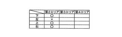
このように、上記4つのエリアについて一通り判定が終わると、図10に示す表ができあがる。 As described above, when the determination is completed for the above four areas, the table shown in FIG. 10 is completed.
図10は、第2エリアに含まれる各領域の判定結果の表を示す図である。 FIG. 10 is a diagram illustrating a determination result table for each region included in the second area.
図10の表では、第2エリアの列で、“下”と書かれた行が“○”となっているが、これは、第2エリア下部領域は除かないと判定されたということ、“左”と書かれた行が“×”となっているが、これは、第2エリア左部領域は除くと判定されたことを意味している。つまり、“○”ならば該当領域は除かない、“×”ならば該当領域は除くという意味である。図10の表のような判定がなされた場合、新しい第2エリアは図11に示すようになり、新しい第2エリアを評価済み第2エリアと呼ぶことにする。 In the table of FIG. 10, in the column of the second area, the row written as “below” is “◯”, which means that it is determined that the lower area of the second area is not excluded, “ The line written “left” is “x”, which means that it is determined that the left area of the second area is excluded. That is, if “◯”, the corresponding area is not excluded, and if “×”, the corresponding area is excluded. When the determination shown in the table of FIG. 10 is made, the new second area is as shown in FIG. 11, and the new second area is called the evaluated second area.
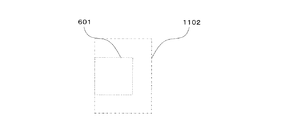
図11は、初期エリアと評価済み第2エリアを示す図であり、図11において601が初期エリア、1102が評価済み第2エリアである。図10の表の“○”、“×”の結果は、取り込まれるデジタル画像によって任意に変わる。 FIG. 11 is a diagram showing the initial area and the evaluated second area. In FIG. 11, 601 is the initial area, and 1102 is the evaluated second area. The results of “◯” and “x” in the table of FIG. 10 arbitrarily vary depending on the digital image to be captured.
図10の表がすべて“×”であった場合、初期エリアを測光エリアとしたまま測光エリアの拡張をストップする。“○”が一つ以上あった場合、上記評価済み第2エリアを新しい測光エリアとして採用して、拡張をストップしてもよいが、引き続き“○”が付いた方向について、上記評価済み第2エリアを更に拡張していく方法について述べる。ここで、上記評価済み第2エリアを測光エリアとして、図5の露出パラメータの調整を行って処理対象デジタル画像を取り込み直すか、行わずに現状保持している処理対象デジタル画像を使うか、行わずに処理対象デジタル画像を取り込み直すからは、どれでもよい。 When all the tables in FIG. 10 are “×”, the expansion of the photometry area is stopped while the initial area is set as the photometry area. If there is more than one “○”, the above-mentioned evaluated second area may be adopted as a new photometric area and expansion may be stopped. Describes how to further expand the area. Here, with the evaluated second area as the photometric area, the exposure parameter adjustment in FIG. 5 is adjusted to recapture the processing target digital image, or the current processing target digital image is used without being performed, or is performed. Any of them may be used because the digital image to be processed is re-imported.
いま、上記評価済み第2エリアを広げて第3エリアを考える。但し、図10の表で“×”となった方向には広げない。つまり、上記評価済み第2エリアを下方向に10ピクセル、上方向に10ピクセル、右方向に10ピクセル広げ、左方向には広げない。広げるサイズは任意である。 Now, consider the third area by expanding the evaluated second area. However, it does not spread in the direction of “x” in the table of FIG. That is, the evaluated second area is expanded 10 pixels downward, 10 pixels upward, 10 pixels right, and not leftward. The spreading size is arbitrary.
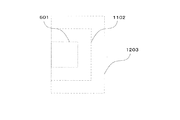
図12は、初期エリアと評価済み第2エリアと第3エリアを示す図であり、ここでは上記第3エリア1203と、初期エリア601と、上記評価済み第2エリア1102を示している。
FIG. 12 is a diagram illustrating the initial area, the evaluated second area, and the third area. Here, the
上記第3エリア内の領域の内、上記評価済み第2エリアより位置的に下にある領域を第3エリア下部領域、位置的に上にある領域を第3エリア上部領域、位置的に右にある領域を第3エリア右部領域と呼ぶことにする。ここで、上記評価済み第2エリアから上記第3エリアを作るときに拡張されなかった方向、ここでは左、の領域は存在しないので考えない。 Of the areas in the third area, the area located below the evaluated second area is the lower area of the third area, the area above the third area is the upper area of the third area, and is positioned to the right. A certain area is called a third area right area. Here, there is no region in the direction that is not expanded when the third area is created from the evaluated second area.
上記第3エリア内に含まれる3つの領域について、上記評価済み第2エリアとの比較を行う。図13のフローを用いて説明する。 The three areas included in the third area are compared with the evaluated second area. This will be described with reference to the flow of FIG.
図13は、評価済み第3エリアを作るときに使われる処理を示すフローチャートである。 FIG. 13 is a flowchart showing the process used when creating the evaluated third area.
まず、ステップS131で、上記評価済み第2エリア内の画素について輝度値の平均を求め、これを評価済み第2エリア輝度平均値と呼ぶ。次いで、ステップS132で上記第3エリア下部領域内の画素について輝度値の平均を求め、これを第3エリア下部領域輝度平均値と呼ぶ。ここで、ステップS131とステップS132はどちらが先に処理されてもよい。次いで、ステップS133で上記評価済み第2エリア輝度平均値と上記第3エリア下部領域輝度平均値を比較する。ステップS134で、二つの平均値の差がある一定量以上あった場合、ステップS135で上記第3エリアから上記第3エリア下部領域を除くということを記憶して本フローを終了する。上記二つの平均値の差がある一定量未満であった場合、ステップS136で上記第3エリア下部領域は除かないということを記憶して本フローを終了する。 First, in step S131, an average luminance value is obtained for the pixels in the evaluated second area, and this is referred to as an evaluated second area luminance average value. Next, in step S132, the average luminance value is obtained for the pixels in the lower area of the third area, and this is called the third area lower area luminance average value. Here, either step S131 or step S132 may be processed first. In step S133, the evaluated second area luminance average value is compared with the third area lower region luminance average value. If it is determined in step S134 that the difference between the two average values is greater than or equal to a certain amount, in step S135 it is stored that the lower area of the third area is excluded from the third area, and this flow is terminated. If the difference between the two average values is less than a certain amount, in step S136 it is stored that the lower area of the third area is not removed, and the present flow is terminated.
上記第3エリア内の他の領域についての評価は、上記第3エリア下部領域を評価した方法と領域の位置の違いを除くと同一である。つまり、上記第3エリア上部領域内の画素について輝度値の平均を求め、これを第3エリア上部領域輝度平均値と呼ぶ、上記評価済み第2エリア輝度平均値と上記第3エリア上部領域輝度平均値を比較して、二つの平均値の差がある一定量以上あった場合、上記第3エリア上部領域は上記第3エリアから除くということを記憶しておく。上記二つの平均値の差がある一定量に満たない場合、上記第3エリア上部領域は上記第3エリアから除かないということを記憶しておく。同様に、上記第3エリア右部領域についても評価を行う。上記複数のエリアの評価を行う順番は任意である。 The evaluation for the other areas in the third area is the same as the method for evaluating the lower area of the third area and the difference in the position of the areas. That is, the average of the luminance values of the pixels in the upper area of the third area is obtained, and this is called the third area upper area luminance average value. The evaluated second area luminance average value and the third area upper area luminance average By comparing the values, it is stored that the upper area of the third area is excluded from the third area when the difference between the two average values exceeds a certain amount. If the difference between the two average values is less than a certain amount, it is stored that the upper area of the third area is not excluded from the third area. Similarly, evaluation is performed for the right area of the third area. The order of evaluating the plurality of areas is arbitrary.
このように、上記3つのエリアについて一通りの評価が終わると、図14に示す表ができあがる。 As described above, when one evaluation is completed for the above three areas, the table shown in FIG. 14 is completed.
図14は、第3エリアに含まれる各領域の判定結果の表を示す図である。また、図15は、初期エリアと評価済み第2エリアと評価済み第3エリアを示す図である。
この例の場合、上記第3エリア下部領域は除く、上記第3エリア上部領域と上記第3エリア右部領域は除かれないことを示している。この結果から新しく作られる第3エリアは図15に示すようになり、新しい第3エリアを評価済み第3エリアと呼ぶことにする。図15の1102が評価済み第2エリア、1503が評価済み第3エリアである。図14の表の“○”、“×”“−”の結果は、取り込まれるデジタル画像によって様々に変わる。
FIG. 14 is a diagram showing a table of determination results for each region included in the third area. FIG. 15 is a diagram illustrating the initial area, the evaluated second area, and the evaluated third area.
In this example, the third area upper region and the third area right region are not excluded except for the third area lower region. From this result, the newly created third area is as shown in FIG. 15, and the new third area is referred to as the evaluated third area. In FIG. 15, 1102 is the evaluated second area, and 1503 is the evaluated third area. The results of “◯”, “×”, “−” in the table of FIG. 14 vary depending on the digital image to be captured.
上記評価済み第3エリアは、右と下へ拡張する方向が残っているので、今まで述べてきた方法と同じように拡張を続けてもよいし、上記評価済み第3エリアを測光エリアとして採用して測光エリアの拡張をストップしてもよい。但し、拡張していく段数については有限回であればよく、回数は任意である。 The evaluated third area remains to expand to the right and down, so expansion may be continued in the same manner as described above, and the evaluated third area is adopted as the photometric area. Then, the expansion of the photometry area may be stopped. However, the number of stages to be expanded may be a finite number of times, and the number of times is arbitrary.
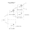
ここで、明るさの判定結果に従ってn(nは2以上の自然数)番のエリアが測光エリアとして採用可能と判定された場合、及び採用不可と判定された場合について図16を参照して少し抽象的に説明する。 Here, referring to FIG. 16, the case where it is determined that the area of n (n is a natural number of 2 or more) number can be adopted as the photometric area and the case where it is determined that the area cannot be adopted according to the brightness determination result is slightly abstract I will explain it.
図16は、明るさの判定結果に従ってn番のエリアを測光エリアとして採用可能/採用不可を説明する図である。 FIG. 16 is a diagram for explaining whether or not the n-th area can be adopted as a photometric area according to the brightness determination result.
図16に示すように、n−1番のエリアの明るさの指標とn番のエリアの明るさの指標比較した判定結果に従ってn番のエリアは測光エリアとして採用可能な場合と測光エリアとして採用不可の場合とに分かれる。但し、上記第2の方法では評価済み第m(mは2以上の自然数)エリアが採用可能/採用不可の対象となる。測光エリアとして採用不可の場合、測光エリアとして使いものにならないと判断してエリアの拡大をストップし、既に採用済みの最大のエリア(この場合、n−1番のエリア)が測光エリアとして使われることになる。一方、n番のエリアが測光エリアとして採用可能な場合、n番のエリアの明るさの指標とn+1番のエリアの明るさの指標を比較した判定結果に従ってn+1番のエリアは測光エリアとして採用可能な場合と測光エリアとして採用不可の場合とに分かれ、以下同様の判定制御が繰り返される。但し、図16に示すように、測光エリアとして採用可能でもエリアの拡大をストップしてもよい。また、エリアの拡大をストップした後に、ある時間をおいてエリアの拡大、及び判定を再開してもよい。 As shown in FIG. 16, the nth area can be used as a photometric area and the photometric area according to the determination result obtained by comparing the brightness index of the n−1 area and the brightness index of the nth area. It is divided into cases where it is impossible. However, in the second method, the evaluated m-th area (m is a natural number of 2 or more) is an object that can be adopted / cannot be adopted. If the photometry area cannot be used, it is determined that the photometry area cannot be used, and the expansion of the area is stopped, and the largest area that has already been adopted (in this case, area n-1) is used as the photometry area. become. On the other hand, when the n-th area can be used as a photometric area, the n + 1-th area can be used as a photometric area according to the determination result obtained by comparing the brightness index of the n-th area with the brightness index of the n + 1 area. And the same determination control is repeated thereafter. However, as shown in FIG. 16, the expansion of the area may be stopped even if it can be adopted as the photometric area. Further, after the area expansion is stopped, the area expansion and determination may be resumed after a certain period of time.
以上のように、本実施の形態のカメラ付き携帯端末10は、画像に含まれる図形コードを解読する図形コード解読部13、撮像部11のデジタル画像の明るさに関係するパラメータを調整する露出制御部15と、各部を制御及び監視するCPU16とを備え、露出制御部15は、測光エリアとして初期測光用の初期エリアを設定し、該初期エリアの明るさに基づいて撮像部11の露出に関係するパラメータを調整し、初期エリアの大きさを変更した測光用の第2のエリアを設定し、該第2のエリアの明るさに基づいて撮像部11の露出に関係するパラメータを調整すると共にその結果を判定する制御を繰り返し実行するので、2次元コードが媒体の端の方に印刷されているような場合でも、カメラの測光エリアが有限の媒体からはみ出しにくくすることができ、カメラの露出に関係するパラメータを図形コードを解読するのに適した明るさの画像を取り込むように調整することができる。パラメータが適切に調整されることにより、媒体と2次元コードのシンボルとの境界の判別が明確となり、解読の成功率を向上させることができる。
As described above, the camera-equipped mobile terminal 10 according to the present embodiment includes the graphic
以上の説明は本発明の好適な実施の形態の例証であり、本発明の範囲はこれに限定されることはない。 The above description is an illustration of a preferred embodiment of the present invention, and the scope of the present invention is not limited to this.
なお、本発明の実施の形態は、上記の実施例に何ら限定されるものではなく、本発明の技術的範囲に属する限り種々の形態を採り得ることはいうまでもない。また、応用に関しても同様である。例えば、本実施の形態では、測光エリアの形を正方形としたが、取り込まれた画像に収まっていればどんな形でもよい。一例を挙げると、初期エリアをひし形として、左上、右上、右下、左下方向に、同様な手法で測光エリアの拡張を検討してもよい。また、本実施の形態では、初期エリアから拡張された領域から4つの領域を抽出して判定を行ったが、抽出する領域の個数は任意であり、より細分化して判定を行ってもよい。 The embodiment of the present invention is not limited to the above-described embodiment, and it goes without saying that various forms can be adopted as long as it belongs to the technical scope of the present invention. The same applies to applications. For example, in the present embodiment, the shape of the photometry area is a square, but it may be any shape as long as it fits in the captured image. For example, the expansion of the photometric area may be examined in the same way in the upper left, upper right, lower right, and lower left directions with the initial area as a diamond. In the present embodiment, the determination is performed by extracting four regions from the region expanded from the initial area. However, the number of regions to be extracted is arbitrary, and the determination may be performed by subdividing.
また、2次元コード等の図形コードを読み取るコード読取装置及びパラメータの調整方法を有する電子機器であればどのような装置にも適用できる。例えば、電子機器としてデジタルカメラやカメラ付き携帯電話装置、PDA等の携帯情報端末、パソコン等の情報処理装置など、カメラ(内蔵/外付け)を備えた装置にも適用可能である。また、読み取り対象となるコードは、QRコードや図形コードに限らず、1次元バーコードであってもよい。 Further, the present invention can be applied to any device as long as it is a code reading device that reads a graphic code such as a two-dimensional code and an electronic device having a parameter adjustment method. For example, the present invention can also be applied to a device equipped with a camera (built-in / external) such as a digital camera, a mobile phone device with a camera, a personal digital assistant such as a PDA, an information processing device such as a personal computer as an electronic device. The code to be read is not limited to a QR code or a graphic code, but may be a one-dimensional barcode.
また、上記実施の形態では、コード読取装置及びパラメータの調整方法という名称を用いたが、これは説明の便宜上であり、2次元コード領域検出装置及び方法、情報読取装置や2次元コード抽出方法等でもよいことは勿論である。 In the above embodiment, the names code reader and parameter adjustment method are used. However, this is for convenience of explanation, and a two-dimensional code area detection device and method, an information reader, a two-dimensional code extraction method, and the like. Of course.
また、上記実施の形態では、図4、図6、図7、図11、図12及び図15に示す領域読取例や図16に示す測光エリア採用/不採用は一例であって他の例でもよいことは言うまでもない。 Further, in the above embodiment, the area reading examples shown in FIGS. 4, 6, 7, 11, 12, and 15 and the photometry area adoption / non-adoption shown in FIG. 16 are examples, and other examples are also possible. Needless to say, it is good.
また、被写体である図形コードが記述された媒体のサイズが有限である場合として、名刺などの紙の媒体の端付近に印刷された2次元コードの例について説明したが、媒体としては紙は勿論のこと、紙などの印刷物に限定されるものではない。例えば、液晶表示部にシンボルが印刷又はカラー表示されている場合の、液晶表示画面を含む概念である。 In addition, an example of a two-dimensional code printed near the edge of a paper medium such as a business card has been described assuming that the size of the medium on which the graphic code that is the subject is described is finite. It is not limited to printed matter such as paper. For example, the concept includes a liquid crystal display screen when symbols are printed or displayed in color on the liquid crystal display unit.
また、上記コード読取装置を構成する各回路部、例えば撮像部やROM,RAM等の記憶部の種類、数及び接続方法などは前述した実施の形態に限られない。 Further, the type, number, connection method, and the like of each circuit unit included in the code reader, for example, an image capturing unit, a storage unit such as a ROM and a RAM, and the like are not limited to the above-described embodiment.
また、以上説明したコード読取装置及びパラメータの調整方法は、これらコード読取装置及びパラメータの調整方法を機能させるためのプログラムでも実現される。このプログラムはコンピュータで読み取り可能な記録媒体に格納されている。本発明では、この記録媒体として、図3に示されているCPU16のメインメモリそのものがプログラムメディアであってもよいし、また外部記憶装置としてCD−ROMドライブ等のプログラム読み取り装置が設けられ、そこに記録媒体を挿入することで読み取り可能なCD−ROM等のプログラムメディアであってもよい。
Further, the code reading device and the parameter adjusting method described above can be realized by a program for causing the code reading device and the parameter adjusting method to function. This program is stored in a computer-readable recording medium. In the present invention, as the recording medium, the main memory itself of the
10 カメラ付き携帯端末(コード読取装置,電子機器)
10a カメラ付き携帯端末本体
11 撮像部(撮像手段)
12 表示部
13 図形コード解読部(図形コード解読手段)
14 入力部
15 露出制御部(露出制御手段)
16 CPU
17 ROM
18 RAM
20 2次元コードが印刷された紙の媒体
110 デジタルカメラ(撮像手段)
210 2次元コード(図形コード)
401 デジタル画像領域
402 測光エリア領域
411 はみ出し領域
601 初期エリア
602 第2エリア
611 第2エリア下部領域
711 第2エリア左部領域
1102 評価済み第2エリア
1203 第3エリア
1503 評価済み第3エリア
10 Mobile terminal with camera (code reader, electronic device)
10a Mobile terminal body with
12
14
16 CPU
17 ROM
18 RAM
20 Paper media printed with 2D code
110 Digital camera (imaging means)
210 Two-dimensional code (graphic code)
401
Claims (21)
前記撮像手段から取り込んだ画像の測光エリアの明るさに応じて、前記撮像手段の露出に関係するパラメータを調整する露出制御手段と、
調整された前記パラメータを使用して、前記撮像手段により取り込まれた画像に含まれる図形コードを解読する図形コード解読手段とを備えるコード読取装置であって、
前記露出制御手段は、前記測光エリアとして初期測光用の初期エリアを用いて前記撮像手段の露出に関係するパラメータを調整することを特徴とするコード読取装置。 Imaging means for imaging a subject;
Exposure control means for adjusting parameters related to exposure of the imaging means according to the brightness of the photometric area of the image captured from the imaging means;
A code reading device comprising graphic code decoding means for decoding a graphic code included in an image captured by the imaging means using the adjusted parameter,
The code reader according to claim 1, wherein the exposure control unit adjusts a parameter related to exposure of the imaging unit by using an initial area for initial photometry as the photometry area.
前記撮像手段から取り込んだ画像の測光エリアの明るさに応じて、前記撮像手段の露出に関係するパラメータを調整する露出制御手段と、
調整された前記パラメータを使用して、前記撮像手段により取り込まれた画像に含まれる図形コードを解読する図形コード解読手段とを備えるコード読取装置であって、
前記露出制御手段は、前記測光エリアとして初期測光用の初期エリアを設定し、該初期エリアの明るさに基づいて前記撮像手段の露出に関係するパラメータを調整し、
前記初期エリアの大きさを変更した測光用のn(nは1から始まる自然数)番のエリアを設定し、該n番のエリアの明るさを判定し、
該明るさの判定結果に従って該n番のエリアが測光エリアとして採用可能と判定された場合は、該n番のエリアの明るさに基づいて前記撮像手段の露出に関係するパラメータを調整し、該n番のエリアの大きさを変更した測光用のn+1番のエリアを設定して、該n+1番のエリアの明るさを判定し、
該n番のエリアが測光エリアとして採用不可と判定された場合は、該n番のエリアの大きさを変更した測光用のn+1番のエリアを設定しない制御を繰り返すことを特徴とするコード読取装置。 Imaging means for imaging a subject;
Exposure control means for adjusting parameters related to exposure of the imaging means according to the brightness of the photometric area of the image captured from the imaging means;
A code reading device comprising graphic code decoding means for decoding a graphic code included in an image captured by the imaging means using the adjusted parameter,
The exposure control means sets an initial area for initial photometry as the photometry area, adjusts a parameter related to exposure of the imaging means based on the brightness of the initial area,
Set an area of n (n is a natural number starting from 1) for photometry with the size of the initial area changed, determine the brightness of the n-th area,
When it is determined that the n-th area can be used as a photometric area according to the brightness determination result, a parameter related to exposure of the imaging unit is adjusted based on the brightness of the n-th area, Set the n + 1 area for photometry with the size of the nth area changed, determine the brightness of the n + 1 area,
When it is determined that the n-th area cannot be adopted as a photometric area, a code reading device is characterized in that the control for not setting the n + 1-th area for photometry in which the size of the n-th area is changed is repeated. .
請求項1乃至11のいずれか一項に記載のコード読取装置を備えることを特徴とする電子機器。 In electronic devices that can read 2D code symbols,
An electronic apparatus comprising the code reading device according to any one of claims 1 to 11.
前記測光エリアとして初期測光用の初期エリアを設定するステップと、
前記初期エリアの明るさに基づいて前記撮像手段の露出に関係するパラメータを調整するステップと、
該初期エリアの大きさを変更した測光用のn(nは1から始まる自然数)番のエリアを設定するステップと、
n番のエリアの明るさの指標を評価するステップと、
前記評価結果に従って前記n番のエリアを測光エリアとして採用するか否かを判定するステップと、
前記n番のエリアを採用する場合は、前記n番のエリアの明るさに基づいて前記撮像手段の露出に関係するパラメータを調整するステップ、又はこのステップを飛ばしたことを意味する空のステップと、
該n番のエリアの大きさを変更した測光用のn+1番のエリアを設定するステップと
を有限回繰り返し実行することを特徴とするパラメータの調整方法。 In a parameter adjustment method for adjusting a parameter related to exposure of the imaging unit according to the brightness of a photometric area of an image captured from the imaging unit,
Setting an initial area for initial metering as the metering area;
Adjusting a parameter related to exposure of the imaging means based on the brightness of the initial area;
Setting an area of n (n is a natural number starting from 1) for photometry in which the size of the initial area is changed;
evaluating the brightness index of the nth area;
Determining whether to adopt the n-th area as a photometric area according to the evaluation result;
In the case of adopting the n-th area, a step of adjusting a parameter related to the exposure of the image pickup means based on the brightness of the n-th area, or an empty step meaning that this step is skipped ,
And a step of setting the (n + 1) th area for photometry in which the size of the nth area is changed.
前記測光エリアとして初期測光用の初期エリアを設定するステップと、
前記初期エリアの明るさに基づいて前記撮像手段の露出に関係するパラメータを調整するステップと、
前記初期エリアを拡張した測光用のn(nは1から始まる自然数)番のエリアを設定するステップと、
前記n番のエリアに含まれるm(mは任意の自然数)個の領域を抽出するステップと、
前記m個の領域のうちの任意のA領域の明るさの指標を評価するステップであり、前記初期エリアの明るさの指標と前記A領域の明るさの指標とを比較するステップと、
前記比較により明るさ指標の差が所定量以上あるときは、前記A領域は明るさを検出する領域として採用せず、前記m個の領域に含まれるA領域を除く領域のそれぞれについて前記A領域と同様な評価を行うステップと、
前記m個の領域に含まれるすべての領域において該採用しない判定がなされなかった場合、該n番のエリアを前記画像内の明るさを検出する領域として採用するステップと
を有することを特徴とするパラメータの調整方法。 In a parameter adjustment method for adjusting a parameter related to exposure of the imaging unit according to the brightness of a photometric area of an image captured from the imaging unit,
Setting an initial area for initial metering as the metering area;
Adjusting a parameter related to exposure of the imaging means based on the brightness of the initial area;
Setting an area of n (n is a natural number starting from 1) for photometry, which is an extension of the initial area;
Extracting m (m is an arbitrary natural number) regions included in the n-th area;
Evaluating a brightness index of an arbitrary A area of the m areas, and comparing a brightness index of the initial area with a brightness index of the A area;
When the difference in the brightness index is greater than or equal to a predetermined amount by the comparison, the A area is not adopted as an area for detecting brightness, and the A area for each of the areas excluding the A area included in the m areas. Performing the same evaluation as
Adopting the n-th area as a region for detecting brightness in the image when the determination is not made in all the regions included in the m regions. Parameter adjustment method.
前記測光エリアとして初期測光用の初期エリアを設定するステップと、
前記初期エリアの明るさに基づいて前記撮像手段の露出に関係するパラメータを調整するステップと、
前記初期エリアを拡張した測光用のn(nは1から始まる自然数)番のエリアを設定するステップと、
前記n番のエリアに含まれるm(mは任意の自然数)個の領域を抽出するステップと、
前記m個の領域のうちの任意のA領域の明るさの指標を評価するステップであり、前記初期エリアの明るさの指標と前記A領域の明るさの指標とを比較するステップと、
前記比較により明るさ指標の差が所定量以上あるときは、前記A領域は明るさを検出する領域として採用せず、前記m個の領域に含まれる前記A領域を除く領域のそれぞれについて前記A領域と同様な評価を行うステップと、
該n番のエリアから前記m個の領域のうち該採用しない判定がなされた領域を除いたエリアを、評価済みn番のエリアとして前記画像内の明るさを検出する領域として採用するステップと
を有することを特徴とするパラメータの調整方法。 In a parameter adjustment method for adjusting a parameter related to exposure of the imaging unit according to the brightness of a photometric area of an image captured from the imaging unit,
Setting an initial area for initial metering as the metering area;
Adjusting a parameter related to exposure of the imaging means based on the brightness of the initial area;
Setting an area of n (n is a natural number starting from 1) for photometry, which is an extension of the initial area;
Extracting m (m is an arbitrary natural number) regions included in the n-th area;
Evaluating a brightness index of an arbitrary A area of the m areas, and comparing a brightness index of the initial area with a brightness index of the A area;
When the difference in brightness index is greater than or equal to a predetermined amount by the comparison, the area A is not adopted as an area for detecting brightness, and the area A is included in each of the areas other than the area A included in the m areas. Performing the same evaluation as the area;
Adopting, as the evaluated n-th area, an area in which the brightness in the image is detected is determined by removing an area from the n-th area that is determined not to be used among the m areas. A parameter adjustment method comprising:
前記n番のエリアは、前記初期エリアを囲む矩形であることを特徴とする請求項13乃至16のいずれか一項に記載のパラメータの調整方法。 The initial area is a rectangular area located in the center direction of the captured image,
The parameter adjustment method according to claim 13, wherein the n-th area is a rectangle surrounding the initial area.
Priority Applications (1)
| Application Number | Priority Date | Filing Date | Title |
|---|---|---|---|
| JP2004109058A JP2005295313A (en) | 2004-04-01 | 2004-04-01 | Code reader, electronic device, parameter adjustment method, and parameter adjustment program |
Applications Claiming Priority (1)
| Application Number | Priority Date | Filing Date | Title |
|---|---|---|---|
| JP2004109058A JP2005295313A (en) | 2004-04-01 | 2004-04-01 | Code reader, electronic device, parameter adjustment method, and parameter adjustment program |
Publications (2)
| Publication Number | Publication Date |
|---|---|
| JP2005295313A true JP2005295313A (en) | 2005-10-20 |
| JP2005295313A5 JP2005295313A5 (en) | 2006-10-19 |
Family
ID=35327741
Family Applications (1)
| Application Number | Title | Priority Date | Filing Date |
|---|---|---|---|
| JP2004109058A Pending JP2005295313A (en) | 2004-04-01 | 2004-04-01 | Code reader, electronic device, parameter adjustment method, and parameter adjustment program |
Country Status (1)
| Country | Link |
|---|---|
| JP (1) | JP2005295313A (en) |
Cited By (6)
| Publication number | Priority date | Publication date | Assignee | Title |
|---|---|---|---|---|
| JP2020160486A (en) * | 2019-03-25 | 2020-10-01 | カシオ計算機株式会社 | Code reading apparatus and program |
| CN112532884A (en) * | 2020-11-27 | 2021-03-19 | 维沃移动通信有限公司 | Identification method and device and electronic equipment |
| CN113065374A (en) * | 2021-04-01 | 2021-07-02 | 支付宝(杭州)信息技术有限公司 | Two-dimensional code identification method, device and equipment |
| CN115474007A (en) * | 2022-08-12 | 2022-12-13 | 北京城市网邻信息技术有限公司 | Shooting method, shooting device, terminal equipment and storage medium |
| CN119808808A (en) * | 2024-11-29 | 2025-04-11 | 北京紫光青藤微系统有限公司 | Inductive control method, device, equipment and medium for barcode reading equipment |
| WO2025192220A1 (en) * | 2024-03-11 | 2025-09-18 | ソニーセミコンダクタソリューションズ株式会社 | Information processing device, information processing method, and imaging device |
Citations (6)
| Publication number | Priority date | Publication date | Assignee | Title |
|---|---|---|---|---|
| JPH04119337A (en) * | 1990-09-11 | 1992-04-20 | Hitachi Ltd | Exposure controller |
| JPH06333068A (en) * | 1993-03-25 | 1994-12-02 | Asahi Optical Co Ltd | Data symbol reader |
| JP2000184271A (en) * | 1998-12-17 | 2000-06-30 | Konica Corp | Digital still camera |
| JP2001188878A (en) * | 2000-01-05 | 2001-07-10 | Olympus Optical Co Ltd | Photometry system for code reader |
| JP2001311980A (en) * | 2000-04-27 | 2001-11-09 | Ricoh Co Ltd | Exposure control device |
| JP2002092542A (en) * | 2000-09-14 | 2002-03-29 | Denso Corp | Optical information reader |
-
2004
- 2004-04-01 JP JP2004109058A patent/JP2005295313A/en active Pending
Patent Citations (6)
| Publication number | Priority date | Publication date | Assignee | Title |
|---|---|---|---|---|
| JPH04119337A (en) * | 1990-09-11 | 1992-04-20 | Hitachi Ltd | Exposure controller |
| JPH06333068A (en) * | 1993-03-25 | 1994-12-02 | Asahi Optical Co Ltd | Data symbol reader |
| JP2000184271A (en) * | 1998-12-17 | 2000-06-30 | Konica Corp | Digital still camera |
| JP2001188878A (en) * | 2000-01-05 | 2001-07-10 | Olympus Optical Co Ltd | Photometry system for code reader |
| JP2001311980A (en) * | 2000-04-27 | 2001-11-09 | Ricoh Co Ltd | Exposure control device |
| JP2002092542A (en) * | 2000-09-14 | 2002-03-29 | Denso Corp | Optical information reader |
Cited By (8)
| Publication number | Priority date | Publication date | Assignee | Title |
|---|---|---|---|---|
| JP2020160486A (en) * | 2019-03-25 | 2020-10-01 | カシオ計算機株式会社 | Code reading apparatus and program |
| JP7367314B2 (en) | 2019-03-25 | 2023-10-24 | カシオ計算機株式会社 | Code reading device, code reading method and program |
| CN112532884A (en) * | 2020-11-27 | 2021-03-19 | 维沃移动通信有限公司 | Identification method and device and electronic equipment |
| CN113065374A (en) * | 2021-04-01 | 2021-07-02 | 支付宝(杭州)信息技术有限公司 | Two-dimensional code identification method, device and equipment |
| CN113065374B (en) * | 2021-04-01 | 2023-10-27 | 支付宝(杭州)信息技术有限公司 | A two-dimensional code recognition method, device and equipment |
| CN115474007A (en) * | 2022-08-12 | 2022-12-13 | 北京城市网邻信息技术有限公司 | Shooting method, shooting device, terminal equipment and storage medium |
| WO2025192220A1 (en) * | 2024-03-11 | 2025-09-18 | ソニーセミコンダクタソリューションズ株式会社 | Information processing device, information processing method, and imaging device |
| CN119808808A (en) * | 2024-11-29 | 2025-04-11 | 北京紫光青藤微系统有限公司 | Inductive control method, device, equipment and medium for barcode reading equipment |
Similar Documents
| Publication | Publication Date | Title |
|---|---|---|
| CN101558416B (en) | Text detection on mobile communications devices | |
| US20030152291A1 (en) | Tilt correction of electronic images | |
| JP5939705B2 (en) | Subject determination device, subject determination method, and program | |
| CN101248454A (en) | Image processing method and apparatus, digital camera, and recording medium for recording image processing program | |
| TWI438766B (en) | Display-mode control device and recording medium storing display-mode control program therein | |
| JP2011513818A (en) | Image capture device with integrated barcode scanning | |
| US7801360B2 (en) | Target-image search apparatus, digital camera and methods of controlling same | |
| JP2004023158A (en) | Imaging device | |
| KR20070098511A (en) | Image processing apparatus, image processing method and imaging apparatus | |
| JP2010224987A (en) | Image processing apparatus, image processing method, program, and recording medium | |
| CN103297681A (en) | Image processing device and image processing method | |
| JP2012027687A (en) | Image processing apparatus and program | |
| CN101141565A (en) | Image processing apparatus, image processing method, computer program, and imaging apparatus | |
| JP2005295313A (en) | Code reader, electronic device, parameter adjustment method, and parameter adjustment program | |
| JP5217872B2 (en) | Symbol reader and program | |
| US10070039B2 (en) | Image processing device and image processing method | |
| US7542074B2 (en) | Photographed image projection device which sets a frame frequency of photographing by a camera based on movement in a photographed image | |
| KR100735262B1 (en) | Automatic display method of mobile terminal | |
| JP4632417B2 (en) | Imaging apparatus and control method thereof | |
| JP2017135755A (en) | Electronic camera and image processing apparatus | |
| US10015339B2 (en) | Image reading apparatus, image reading method, and recording medium therefor, that improve quality of image of document obtained by portable image device | |
| WO2017126056A1 (en) | Mobile terminal, image processing method, and program | |
| JP2003203198A (en) | Imaging device, imaging method, computer-readable storage medium, and computer program | |
| JP2005055973A (en) | Portable information terminal | |
| JP5482925B2 (en) | Image capturing apparatus and program |
Legal Events
| Date | Code | Title | Description |
|---|---|---|---|
| A521 | Request for written amendment filed |
Free format text: JAPANESE INTERMEDIATE CODE: A523 Effective date: 20060901 |
|
| A621 | Written request for application examination |
Free format text: JAPANESE INTERMEDIATE CODE: A621 Effective date: 20060901 |
|
| A131 | Notification of reasons for refusal |
Free format text: JAPANESE INTERMEDIATE CODE: A131 Effective date: 20100223 |
|
| A02 | Decision of refusal |
Free format text: JAPANESE INTERMEDIATE CODE: A02 Effective date: 20100629 |