JP2005295097A - Harmonic mixer and wireless apparatus provided with the same - Google Patents
Harmonic mixer and wireless apparatus provided with the same Download PDFInfo
- Publication number
- JP2005295097A JP2005295097A JP2004105684A JP2004105684A JP2005295097A JP 2005295097 A JP2005295097 A JP 2005295097A JP 2004105684 A JP2004105684 A JP 2004105684A JP 2004105684 A JP2004105684 A JP 2004105684A JP 2005295097 A JP2005295097 A JP 2005295097A
- Authority
- JP
- Japan
- Prior art keywords
- signal
- local oscillation
- harmonic mixer
- harmonic
- mixer according
- Prior art date
- Legal status (The legal status is an assumption and is not a legal conclusion. Google has not performed a legal analysis and makes no representation as to the accuracy of the status listed.)
- Granted
Links
- 230000010355 oscillation Effects 0.000 claims abstract description 40
- 239000003990 capacitor Substances 0.000 claims description 15
- 238000004891 communication Methods 0.000 abstract description 10
- 239000000969 carrier Substances 0.000 abstract 1
- 230000005540 biological transmission Effects 0.000 description 9
- 238000010586 diagram Methods 0.000 description 8
- 238000012986 modification Methods 0.000 description 4
- 230000004048 modification Effects 0.000 description 4
- 238000005516 engineering process Methods 0.000 description 2
- 230000007613 environmental effect Effects 0.000 description 2
- 238000000034 method Methods 0.000 description 2
- 230000000903 blocking effect Effects 0.000 description 1
- 238000004519 manufacturing process Methods 0.000 description 1
- 238000001228 spectrum Methods 0.000 description 1
Images
Classifications
-
- H—ELECTRICITY
- H03—ELECTRONIC CIRCUITRY
- H03D—DEMODULATION OR TRANSFERENCE OF MODULATION FROM ONE CARRIER TO ANOTHER
- H03D9/00—Demodulation or transference of modulation of modulated electromagnetic waves
- H03D9/06—Transference of modulation using distributed inductance and capacitance
- H03D9/0608—Transference of modulation using distributed inductance and capacitance by means of diodes
- H03D9/0633—Transference of modulation using distributed inductance and capacitance by means of diodes mounted on a stripline circuit
-
- H—ELECTRICITY
- H03—ELECTRONIC CIRCUITRY
- H03D—DEMODULATION OR TRANSFERENCE OF MODULATION FROM ONE CARRIER TO ANOTHER
- H03D7/00—Transference of modulation from one carrier to another, e.g. frequency-changing
- H03D7/02—Transference of modulation from one carrier to another, e.g. frequency-changing by means of diodes
Landscapes
- Engineering & Computer Science (AREA)
- Power Engineering (AREA)
- Physics & Mathematics (AREA)
- Electromagnetism (AREA)
- Transmitters (AREA)
- Superheterodyne Receivers (AREA)
Abstract
Description
本発明はハーモニックミキサ及びこれを備えた無線装置に関し、特に30GHz以上の高周波数帯に好適な送信技術に関する。 The present invention relates to a harmonic mixer and a radio apparatus including the same, and more particularly to a transmission technique suitable for a high frequency band of 30 GHz or higher.
近年、30GHz以上の準ミリ波周波数帯やミリ波周波数帯を用いる通信技術の研究が活発化している。このような高周波数帯では、安定した局部発振周波数を生成するのが難しい。送信側及び受信側にそれぞれ安定した局部発振周波数を設けない限り、高品質な通信を実現することは困難である。 In recent years, research on communication technology using a quasi-millimeter wave frequency band of 30 GHz or more and a millimeter-wave frequency band has been activated. In such a high frequency band, it is difficult to generate a stable local oscillation frequency. Unless a stable local oscillation frequency is provided on each of the transmission side and the reception side, it is difficult to realize high-quality communication.
特許文献1には、局部発振周波数を持つ無変調キャリアを無線変調信号とともに送信する技術が開示されている。受信側では、受信した無変調キャリアを局部発振周波数として用い、無線変調信号を復調する。受信側に高精度な局部発振器を設ける必要がないので、受信装置の構成を簡単化することができる。また、無変調キャリアと無線変調キャリアが同じ環境要因(例えば温度変動など)の影響を受けている場合には、受信した無変調キャリアを用いて復調することで、その環境要因による影響(例えば、温度変動による揺らぎ)を相殺することができ、良好な通信品質を提供することができる。
しかしながら、特許文献1に記載の発明は、空中線出力される無変調キャリアと同一の発振周波数を発生する局部発振器を用いているため、安定した無線変調キャリアを生成することができないという問題点を有する。30GHz以上の発振周波数を安定して発振することができる能力を持つ局部発振器は、現在の技術では解決しなければならない課題が多い。特に、最近注目されている60GHz帯のミリ波無線通信を実現するために必要な60GHzの局部発振器を製作することは、極めて高度な技術を要し、しかも大変高価である。 However, since the invention described in Patent Document 1 uses a local oscillator that generates the same oscillation frequency as an unmodulated carrier that is output as an antenna, there is a problem in that a stable wireless modulated carrier cannot be generated. . A local oscillator having the ability to stably oscillate an oscillation frequency of 30 GHz or more has many problems that must be solved by current technology. In particular, it is very expensive to manufacture a local oscillator of 60 GHz necessary for realizing the millimeter-wave wireless communication in the 60 GHz band, which has recently been attracting attention.
従って、本発明は、安定した局部発振周波数を生成することが困難な30GHz以上の高周波数帯を用いた無線通信を安価かつ簡単な構成で実現することができるハーモニックミキサ及びこれを備えた無線装置を提供することを目的とする。 Therefore, the present invention provides a harmonic mixer capable of realizing wireless communication using a high frequency band of 30 GHz or higher, which is difficult to generate a stable local oscillation frequency, with a low-cost and simple configuration, and a wireless device including the same The purpose is to provide.
本発明は、請求項1に記載のように、一端及び他端に互いに逆の極性どうしが接続されたアンチパラレル・ダイオードの一端に局部発振信号を与え、他端に情報信号を与えるとともに直流バイアスを与え、前記他端から出力信号を取り出すハーモニックミキサである。アンチパラレル・ダイオードの機能により、局部発振信号の高調波で情報信号をアップコンバートした信号が得られるとともに、直流バイアスにより、局部発振信号の高調波を出力することができる。この高調波を無変調キャリアとして、アップコンバートされた信号とともに送信することにより、高周波数帯を用いた無線通信を安価かつ簡単な構成で実現することができる。 According to the present invention, a local oscillation signal is applied to one end of an anti-parallel diode having opposite polarities connected to one end and the other end, an information signal is applied to the other end, and a DC bias is applied. And a harmonic mixer that takes out an output signal from the other end. With the function of the anti-parallel diode, a signal obtained by up-converting the information signal with the harmonic of the local oscillation signal can be obtained, and the harmonic of the local oscillation signal can be output by the DC bias. By transmitting this harmonic as an unmodulated carrier together with the up-converted signal, wireless communication using a high frequency band can be realized with an inexpensive and simple configuration.
請求項2に記載の発明は、請求項1に記載のハーモニックミキサにおいて、前記出力信号に含まれる高調波成分の波長の1/4の長さのオープンスタブを前記他端に接続したことを特徴とする。 According to a second aspect of the present invention, in the harmonic mixer according to the first aspect, an open stub having a length of 1/4 of the wavelength of the harmonic component included in the output signal is connected to the other end. And
請求項3に記載の発明は、請求項1に記載のハーモニックミキサにおいて、前記出力信号に含まれ、かつ前記局部発振信号の高調波成分で前記情報信号をアップコンバートした信号の波長の1/4の長さのショートスタブを前記一端に接続したことを特徴とする。 According to a third aspect of the present invention, in the harmonic mixer according to the first aspect, a quarter of a wavelength of a signal included in the output signal and up-converted from the information signal with a harmonic component of the local oscillation signal. A short stub having a length of 1 mm is connected to the one end.
請求項4に記載の発明は、請求項1に記載のハーモニックミキサにおいて、前記出力信号に含まれる高調波成分の波長の1/4の長さのオープンスタブを前記他端に接続し、前記出力信号に含まれ、かつ前記局部発振信号の高調波成分で前記情報信号をアップコンバートした信号の波長の1/4の長さのショートスタブを前記一端に接続したことを特徴とする。 According to a fourth aspect of the present invention, in the harmonic mixer according to the first aspect, an open stub having a length of 1/4 of the wavelength of the harmonic component included in the output signal is connected to the other end, and the output A short stub having a length of ¼ of the wavelength of a signal included in the signal and up-converted from the information signal with a harmonic component of the local oscillation signal is connected to the one end.
請求項5に記載の発明は、請求項3又は4に記載のハーモニックミキサにおいて、前記ショートスタブは、前記アップコンバート信号の少なくとも一方の側波帯の中心周波数に相当する波長の1/4の長さを有することを特徴とする。 According to a fifth aspect of the present invention, in the harmonic mixer according to the third or fourth aspect, the short stub has a length of ¼ of a wavelength corresponding to a center frequency of at least one sideband of the up-converted signal. It is characterized by having.
請求項6に記載の発明は、請求項1から5のいずれか一項記載のハーモニックミキサにおいて、前記他端に接続されるローパスフィルタを有し、該ローパスフィルタを介して前記情報信号を前記アンチパラレル・ダイオードに印加することを特徴とする。 A sixth aspect of the present invention is the harmonic mixer according to any one of the first to fifth aspects, further comprising a low-pass filter connected to the other end, and the information signal is received through the low-pass filter. It is applied to a parallel diode.
請求項7に記載の発明は、請求項1から6のいずれか一項記載のハーモニックミキサにおいて、前記他端に接続されたキャパシタを有し、該キャパシタを通して前記出力信号を取り出すことを特徴とする。 A seventh aspect of the present invention is the harmonic mixer according to any one of the first to sixth aspects, wherein the harmonic mixer has a capacitor connected to the other end, and the output signal is taken out through the capacitor. .
請求項8に記載の発明は、請求項1から7のいずれか一項記載のハーモニックミキサにおいて、前記一端に接続されたキャパシタを有し、該キャパシタを通して前記局部発振信号を前記アンチパラレル・ダイオードに印加することを特徴とする。 An eighth aspect of the present invention is the harmonic mixer according to any one of the first to seventh aspects, further comprising a capacitor connected to the one end, and passing the local oscillation signal to the anti-parallel diode through the capacitor. It is characterized by applying.
請求項9に記載の発明は、前記局部発振信号を出力する局部発振器と、前記直流バイアスを受け取る端子と、請求項1から8のいずれかに記載のハーモニックミキサとを備えたことを特徴とする無線装置である。
The invention described in
安定した局部発振周波数を生成することが困難な30GHz以上の高周波数帯を用いた無線通信を安価かつ簡単な構成で実現することができるハーモニックミキサ及びこれを備えた無線装置を提供することができる。 A harmonic mixer capable of realizing wireless communication using a high frequency band of 30 GHz or more, which is difficult to generate a stable local oscillation frequency, with a low-cost and simple configuration and a wireless device including the harmonic mixer can be provided. .
以下、本発明の実施例を添付図面を参照して詳細に説明する。 Hereinafter, embodiments of the present invention will be described in detail with reference to the accompanying drawings.
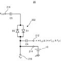
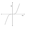
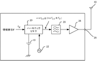
図1は、本発明の実施例1に係るハーモニックミキサ20の構成を示すブロック図である。ハーモニックミキサは、例えば送信側の無線装置に設けられる。ハーモニックミキサ20は、アンチパラレル・ダイオード(APDP)202を有する。APDP202は2つのダイオードD1とD2を逆方向に並列に接続した構成を有する。APDP202は、図2に示すような電流・電圧特性を持つ。この電流・電圧特性の非線形な部分を利用することで、その一端に与えられた入力信号の高調波を発生する。入力信号として、後述する局部発振器が発生する局部発振信号が、外部接続端子216及びキャパシタC5を介してAPDP202の一端に与えられる。以下、局部発振信号の周波数をfLOで表す。他端には、情報信号が与えられる。情報信号の周波数をfIFで表す。APDP202は、局部発振信号の周波数成分fLOのn倍波(nは2以上の自然数)の高調波を発生し、この高調波成分と情報信号とを混合する。この出力は、APDP202の他端からキャパシタC4を介して外部接続端子212に与えられる。従って、外部接続端子212には、周波数n・fLO±fIFの信号出力が得られる。例えば、局部発振信号の周波数fLOを30GHzとし、情報信号の周波数fIFを5GHzとし、n=2の場合に着目すれば、外部接続端子212には55GHzと65GHzのアップコンバートされた信号(無線変調波)が得られる。
FIG. 1 is a block diagram showing a configuration of a
ここで、以下に説明する直流バイアスがない状態では、上記動作において2倍の高調波成分はAPDP202内でキャンセルされてしまい、出力端子として機能する外部接続端子212には現れない。これに対し、本実施例では、APDP202の他端に、端子214を介して直流電圧源10が接続されている。直流電圧源10はバイアス電源として機能し、直流電圧をAPDP202の他端に印加する。これにより、APDP202がバイアスされ、APDP202の動作特性がオフセットされる。この結果、局部発振周波数の2倍の高調波成分2fLOがAPDP202でキャンセルされずに出力される。別の観点から説明すると、この出力は、周波数ゼロの無変調信号(つまり、直流電圧)が局部発振信号fLOに混合された結果である。fLO=30GHzの例では、60GHzの信号がキャパシタC4を介して外部接続端子212に出力される。
Here, in the state where there is no DC bias described below, the double harmonic component in the above operation is canceled in the APDP 202 and does not appear on the
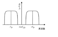
以上のとおり、ハーモニックミキサ20は、図3(a)に示すように、周波数n・fLO±fIFの信号(上記の例では55GHzと65GHz)と、n・fLOの信号(上記の例では60GHz)とを生成することができる。周波数n・fLO±fIFの信号を無線変調信号として送信し、周波数n・fLOの信号を空中線送信用局部発振信号として送信する。受信側では、受信した局部発振信号を用いて無線変調信号を復調することができる。無線変調信号と空中線送信用局部発振信号とはAPDP202で発生するため同じ揺らぎ成分を含んでいるので、復調によりこれらの揺らぎ成分を相殺することができる。また、n・fLOの空中線送信用局部発振信号を生成するのにfLOの発振周波数を持つ局部発振器を用いればよいので、簡単な構成で安定した30GHz以上の無線通信を実現することができる。なお、空中線送信用局部発振信号と無線信号とは同じ電力を持つことが好ましい。電力が異なると、相殺後に揺らぎ成分が残る可能性がある。直流バイアスの電圧値を調整することで空中線送信用局部発振信号の電力を容易に調整することができる。
As described above, the
なお、図1に示すキャパシタC3とC4は、直流電圧源10を設けたことに起因して用いられているもので、直流電圧を遮断する役目を持つ。
The capacitors C3 and C4 shown in FIG. 1 are used due to the provision of the
次に、実施例2として、上記ハーモニックミキサ20を備えた無線装置を説明する。
Next, as a second embodiment, a radio apparatus including the
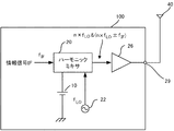
図4は、本発明の実施例2に係る無線装置100の構成を示すブロック図である。この無線装置100は、直流電圧源10、ハーモニックミキサ20、局部発振器22、電力増幅器26及び外部接続端子29を有する。局部発振器22は、周波数fLOの局部発振信号を生成する。前述したハーモニックミキサ20の出力信号は電力増幅器26で増幅され、外部接続端子29に接続されたアンテナ40を介して送信される。図5に示すように、電力増幅器26の前段にバンドパスフィルタ28を設けることで、不要な信号成分を取り除くことができる。例えば、バンドパスフィルタ28を用いて、2・fLO±fIFの無線変調信号、及び2・fLOの空中線送信用局部発振信号以外の不要波を取り除くことや、一方の無線変調信号を取り除くことができる。
FIG. 4 is a block diagram illustrating a configuration of the
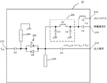
図5は、ハーモニックミキサ20の具体的な構成例を示す回路図である。図示する回路は図を分かりやすくするために、理想線路を用いて回路部品間を接続した様子を示す。APDP202の一端には、外部接続端子216及びキャパシタC5を介して局部発振器22の出力信号が与えられる。APDP202の他端には、外部接続端子210、デカップリング・キャパシタC3及びローパスフィルタ208を介して、情報信号IFが与えられる。ローパスフィルタ208は、2つのキャパシタC1、C2とインダクタL1とを有する。また、外部接続端子214、インダクタL2、及びローパスフィルタ208を介して、直流バイアスがAPDP202の他端に与えられている。インダクタL2は高周波成分が直流電圧源10に印加されるのを防止する。
FIG. 5 is a circuit diagram illustrating a specific configuration example of the
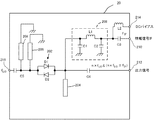
オープンスタブ204及びショートスタブ206は、信号損失を抑制して効率を高めるために設けられており、省略することも可能である。オープンスタブ204は、APDP202の出力側に接続されており、局部発振器22の局部発振周波数fLOに相当する波長の1/4の長さを持つ。従って、局部発振周波数fLO(上記例では、30GHz)の信号に対して、オープンスタブ204の開放端はグランドとして機能する。これにより、APDP202の両端間に30GHzの信号が効率よく印加される。60GHzの信号に対してオープンスタブ204は見えない。ショートスタブ206はAPDP202の入力側に接続されており、無線変調信号2fLO±fIF(上記の例では、55GHzと65GHz)のいずれかの周波数に相当する波長の1/4の長さを持つ。例えば、ショートスタブ206が65GHzの無線変調信号の波長の1/4の長さを持つ場合、APDP202の入力側端とグランドとの間に65GHzの無線変調信号が効率よく印加されるので、65GHzの無線変調信号をAPDP202側に折り返すことができる。勿論、ショートスタブ206は55GHzの無線変調信号の波長の1/4n長さを持つ構成であってもよい。無線変調信号は、両側波を送信することもできるし、片方のみを送信することもできる。片方のみを送信する場合には、ショートスタブ206は1つでよい。両方送信する場合には、図7に示すように、更にショートスタブ208を設け、55MHzと65MHzの両無線変調信号に対応することが好ましい。
The
以上説明したように、無線装置100は30GHz以上の高周波数帯を用いた無線通信を安価かつ簡単な構成で実現することができる。
As described above, the
以上、本発明の2つの実施例及びその変形例を説明した。本発明はこれらに限定されるものではなく、他の実施例や変形例を含むものである。 The two embodiments of the present invention and the modifications thereof have been described above. The present invention is not limited to these, and includes other embodiments and modifications.
10 直流電圧源
20 ハーモニックミキサ 22 局部発振器
24 増幅器 26 電力増幅器
28 バンドパスフィルタ 100 無線装置
202 アンチパラレル・ダイオード(APDP)
204 オープンスタブ
206、208 ショートスタブ
DESCRIPTION OF
202 Anti-parallel diode (APDP)
204
Claims (9)
前記出力信号に含まれ、かつ前記局部発振信号の高調波成分で前記情報信号をアップコンバートした信号の波長の1/4の長さのショートスタブを前記一端に接続したことを特徴とする請求項1記載のハーモニックミキサ。 An open stub having a length of ¼ of the wavelength of the harmonic component contained in the output signal is connected to the other end;
The short stub having a length of 1/4 of a wavelength of a signal included in the output signal and up-converted from the information signal by a harmonic component of the local oscillation signal is connected to the one end. The harmonic mixer according to 1.
Priority Applications (3)
| Application Number | Priority Date | Filing Date | Title |
|---|---|---|---|
| JP2004105684A JP4421350B2 (en) | 2004-03-31 | 2004-03-31 | Harmonic mixer and radio apparatus including the same |
| US11/094,533 US20050221772A1 (en) | 2004-03-31 | 2005-03-31 | Harmonic mixer and radio communication device having the same |
| EP05252027A EP1605585B1 (en) | 2004-03-31 | 2005-03-31 | Harmonic mixer using anti parallel diodes |
Applications Claiming Priority (1)
| Application Number | Priority Date | Filing Date | Title |
|---|---|---|---|
| JP2004105684A JP4421350B2 (en) | 2004-03-31 | 2004-03-31 | Harmonic mixer and radio apparatus including the same |
Publications (3)
| Publication Number | Publication Date |
|---|---|
| JP2005295097A true JP2005295097A (en) | 2005-10-20 |
| JP2005295097A5 JP2005295097A5 (en) | 2007-05-24 |
| JP4421350B2 JP4421350B2 (en) | 2010-02-24 |
Family
ID=34940677
Family Applications (1)
| Application Number | Title | Priority Date | Filing Date |
|---|---|---|---|
| JP2004105684A Expired - Fee Related JP4421350B2 (en) | 2004-03-31 | 2004-03-31 | Harmonic mixer and radio apparatus including the same |
Country Status (3)
| Country | Link |
|---|---|
| US (1) | US20050221772A1 (en) |
| EP (1) | EP1605585B1 (en) |
| JP (1) | JP4421350B2 (en) |
Cited By (5)
| Publication number | Priority date | Publication date | Assignee | Title |
|---|---|---|---|---|
| JP2007235368A (en) * | 2006-02-28 | 2007-09-13 | Nec Corp | Even harmonic mixer |
| JP2007274040A (en) * | 2006-03-30 | 2007-10-18 | Nec Corp | Harmonic mixer circuit |
| DE102008012984A1 (en) | 2007-07-09 | 2009-01-15 | Mitsubishi Electric Corp. | Mixer circuit and radar transceiver |
| JP2009094693A (en) * | 2007-10-05 | 2009-04-30 | Toshiba Corp | Mixer circuit |
| JP2015180060A (en) * | 2014-02-28 | 2015-10-08 | 地方独立行政法人東京都立産業技術研究センター | Frequency converter, measurement system, and measurement method |
Families Citing this family (4)
| Publication number | Priority date | Publication date | Assignee | Title |
|---|---|---|---|---|
| FR2871629A1 (en) * | 2004-06-09 | 2005-12-16 | Thomson Licensing Sa | FREQUENCY CONVERTING DEVICE, METHOD OF CALIBRATING THE DEVICE, AND SYSTEM FOR TRANSMITTING / RECEIVING ELECTROMAGNETIC SIGNALS HAVING SUCH A DEVICE |
| GB0603193D0 (en) * | 2006-02-16 | 2006-03-29 | Thruvision Ltd | Detection method and apparatus |
| US8559905B2 (en) * | 2007-12-05 | 2013-10-15 | Viasat, Inc. | Systems, devices, and methods for suppressing frequency spurs in mixers |
| US9472685B2 (en) * | 2013-04-05 | 2016-10-18 | Joshua D. Kaggie | Methods of circuit construction to improve diode performance |
Family Cites Families (9)
| Publication number | Priority date | Publication date | Assignee | Title |
|---|---|---|---|---|
| US4320536A (en) * | 1979-09-18 | 1982-03-16 | Dietrich James L | Subharmonic pumped mixer circuit |
| JPS58101510A (en) * | 1981-12-11 | 1983-06-16 | Nec Corp | Frequency converter using microwave integrated circuit |
| US4420839A (en) * | 1982-03-30 | 1983-12-13 | Bunker Ramo-Eltra Corporation | Hybrid ring having improved bandwidth characteristic |
| US5127102A (en) * | 1991-01-15 | 1992-06-30 | Raytheon Company | Radio frequency mixer circuits |
| US5856801A (en) * | 1997-09-12 | 1999-01-05 | Valentine Research, Inc. | Input stage for a police radar detector |
| IT1294732B1 (en) * | 1997-09-15 | 1999-04-12 | Italtel Spa | IMAGE REJECTION SUBHARMONIC FREQUENCY CONVERTER MADE IN MICRO-STRIP, PARTICULARLY SUITABLE FOR USE IN |
| JP2001053640A (en) * | 1999-08-11 | 2001-02-23 | Communication Research Laboratory Mpt | Device and method for radio communication |
| AU2001251472A1 (en) * | 2000-07-17 | 2002-01-30 | Raytheon Company | Mixer using diodes |
| US7164902B2 (en) * | 2001-11-01 | 2007-01-16 | Sharp Kabushiki Kaisha | Filter-integrated even-harmonic mixer and hi-frequency radio communication device using the same |
-
2004
- 2004-03-31 JP JP2004105684A patent/JP4421350B2/en not_active Expired - Fee Related
-
2005
- 2005-03-31 EP EP05252027A patent/EP1605585B1/en not_active Expired - Fee Related
- 2005-03-31 US US11/094,533 patent/US20050221772A1/en not_active Abandoned
Cited By (10)
| Publication number | Priority date | Publication date | Assignee | Title |
|---|---|---|---|---|
| JP2007235368A (en) * | 2006-02-28 | 2007-09-13 | Nec Corp | Even harmonic mixer |
| JP2007274040A (en) * | 2006-03-30 | 2007-10-18 | Nec Corp | Harmonic mixer circuit |
| DE102008012984A1 (en) | 2007-07-09 | 2009-01-15 | Mitsubishi Electric Corp. | Mixer circuit and radar transceiver |
| US7538719B2 (en) | 2007-07-09 | 2009-05-26 | Mitsubishi Electric Corporation | Mixer circuit and radar transceiver |
| JP2009094693A (en) * | 2007-10-05 | 2009-04-30 | Toshiba Corp | Mixer circuit |
| JP2015180060A (en) * | 2014-02-28 | 2015-10-08 | 地方独立行政法人東京都立産業技術研究センター | Frequency converter, measurement system, and measurement method |
| WO2016136947A1 (en) * | 2015-02-27 | 2016-09-01 | 地方独立行政法人東京都立産業技術研究センター | Frequency converter, measuring system, and measuring method |
| CN107251416A (en) * | 2015-02-27 | 2017-10-13 | 地方独立行政法人东京都立产业技术研究中心 | Frequency converter, measuring system and measuring method |
| US10649013B2 (en) | 2015-02-27 | 2020-05-12 | Tokyo Metropolitan Industrial Technology Research Institute | Frequency converter, measuring system, and measuring method |
| CN107251416B (en) * | 2015-02-27 | 2021-06-15 | 地方独立行政法人东京都立产业技术研究中心 | Frequency converter, measuring system and measuring method |
Also Published As
| Publication number | Publication date |
|---|---|
| EP1605585B1 (en) | 2012-07-04 |
| EP1605585A1 (en) | 2005-12-14 |
| US20050221772A1 (en) | 2005-10-06 |
| JP4421350B2 (en) | 2010-02-24 |
Similar Documents
| Publication | Publication Date | Title |
|---|---|---|
| US6704558B1 (en) | Image-reject down-converter and embodiments thereof, such as the family radio service | |
| US8594228B2 (en) | Apparatus and method of differential IQ frequency up-conversion | |
| US20020180538A1 (en) | Local oscillator architecture to reduce transmitter pulling effect and minimize unwanted sideband | |
| US8938204B2 (en) | Signal generator circuit and radio transmission and reception device including the same | |
| US7471939B2 (en) | Multiplier and radio communication apparatus using the same | |
| JP2013523056A (en) | Frequency multiplier transceiver | |
| CN101785191A (en) | LO 2LO upconverter for an inphase/quadrature phase modulator | |
| CN101395810B (en) | Apparatus with noise reduction for receiving and/or sending radiofrequency signals | |
| JP4421350B2 (en) | Harmonic mixer and radio apparatus including the same | |
| JP4640454B2 (en) | Modulation circuit, modulation method, program, and communication apparatus | |
| US8885768B2 (en) | Low-loss, broad band, LC I/Q phase shifter | |
| US6983131B2 (en) | Circuit configuration for direct modulation | |
| US9614552B2 (en) | Millimeter-wave modulation device | |
| JP4391291B2 (en) | Wireless device | |
| US20050255806A1 (en) | 2N-order sub-harmonic frequency modulator having high carrier suppression ratio and direct conversion transmitter using the same | |
| Agrawal et al. | Multi-band RF time delay element based on frequency translation | |
| WO2026048320A1 (en) | Communication device and communication system | |
| US20250183903A1 (en) | Quadrature harmonic self-oscillating mixer for multi-function wireless communication and sensing systems and methods thereof | |
| JP2026047068A (en) | Communication equipment and communication systems | |
| JP2003152558A (en) | Wireless circuit | |
| WO2026048284A1 (en) | Communication device, communication system, and imaging system | |
| JP2008022045A (en) | Receiver, transmitter and data communication system | |
| JP2026047069A (en) | Communication devices, communication systems, and imaging systems | |
| JPH11313116A (en) | Communication device | |
| JP4245342B2 (en) | Mixer, receiver and transmitter |
Legal Events
| Date | Code | Title | Description |
|---|---|---|---|
| A521 | Request for written amendment filed |
Free format text: JAPANESE INTERMEDIATE CODE: A523 Effective date: 20070326 |
|
| A621 | Written request for application examination |
Free format text: JAPANESE INTERMEDIATE CODE: A621 Effective date: 20070326 |
|
| A131 | Notification of reasons for refusal |
Free format text: JAPANESE INTERMEDIATE CODE: A131 Effective date: 20090811 |
|
| A521 | Request for written amendment filed |
Free format text: JAPANESE INTERMEDIATE CODE: A523 Effective date: 20090918 |
|
| TRDD | Decision of grant or rejection written | ||
| A01 | Written decision to grant a patent or to grant a registration (utility model) |
Free format text: JAPANESE INTERMEDIATE CODE: A01 Effective date: 20091201 |
|
| A01 | Written decision to grant a patent or to grant a registration (utility model) |
Free format text: JAPANESE INTERMEDIATE CODE: A01 |
|
| A61 | First payment of annual fees (during grant procedure) |
Free format text: JAPANESE INTERMEDIATE CODE: A61 Effective date: 20091202 |
|
| FPAY | Renewal fee payment (event date is renewal date of database) |
Free format text: PAYMENT UNTIL: 20121211 Year of fee payment: 3 |
|
| R150 | Certificate of patent or registration of utility model |
Free format text: JAPANESE INTERMEDIATE CODE: R150 |
|
| FPAY | Renewal fee payment (event date is renewal date of database) |
Free format text: PAYMENT UNTIL: 20131211 Year of fee payment: 4 |
|
| LAPS | Cancellation because of no payment of annual fees |