JP2005295079A - Antenna mast mounting bracket and antenna device - Google Patents
Antenna mast mounting bracket and antenna device Download PDFInfo
- Publication number
- JP2005295079A JP2005295079A JP2004105480A JP2004105480A JP2005295079A JP 2005295079 A JP2005295079 A JP 2005295079A JP 2004105480 A JP2004105480 A JP 2004105480A JP 2004105480 A JP2004105480 A JP 2004105480A JP 2005295079 A JP2005295079 A JP 2005295079A
- Authority
- JP
- Japan
- Prior art keywords
- antenna
- mounting
- support rod
- antenna mast
- mounting bracket
- Prior art date
- Legal status (The legal status is an assumption and is not a legal conclusion. Google has not performed a legal analysis and makes no representation as to the accuracy of the status listed.)
- Granted
Links
Images
Landscapes
- Support Of Aerials (AREA)
Abstract
【課題】小型で安価且つ取付け易くする。
【解決手段】前方側に形成した係止部とこの後方側に連設された取付部であって,この取付部に立設されアンテナマストと当接する第1及び第2の折曲板部と,第1及び前記第2の折曲板部との間に位置し,取付部よりアンテナマスト側に突出成形した突出堤部と,この突出堤部の両端部の中央から取付部にかけて連通させた長孔とからなる取付アングルと,長孔に取付部の後方側から折曲部を挿入し,連結部を前記突出堤部の内面側に組込み,突出堤部を支点として少なくとも90°回動自在とするU字ボルトと,この折曲部を両端部に挿通し,当該アンテナマストを前記取付アングルと挟持する挟持片と,前記U字ボルトの折曲部の螺子に螺合させ,前記挟持片を前記取付アングル固着するナットとからなり,前記取付アングルの取付部は,アンテナ反射器と着脱自在に固着する。
。
【選択図】 図3An object of the present invention is to make it small, inexpensive and easy to install.
A locking portion formed on the front side and a mounting portion continuously provided on the rear side, the first and second bent plate portions standing on the mounting portion and contacting the antenna mast, , Located between the first and the second bent plate portion, and a projecting ridge portion projecting from the mounting portion to the antenna mast side and communicated from the center of both ends of the projecting ridge portion to the mounting portion. A mounting angle consisting of a long hole, and a bent part is inserted into the long hole from the rear side of the mounting part. The connecting part is built into the inner surface side of the protruding bank part and can be rotated at least 90 ° with the protruding bank part as a fulcrum. A U-bolt, and a bent piece that is inserted into both ends of the U-bolt, and the antenna mast is clamped to the mounting angle, and a screw of the bent portion of the U-bolt is screwed to the clamped piece. And a mounting portion of the mounting angle. , Removably fixed to the antenna reflector.
.
[Selection] Figure 3
Description
本発明は,主にアンテナをアンテナマストに取付けるためのアンテナマスト取付金具の機構に関するものであり,特にアンテナを安全に組み付け可能で,コンパクトに構成できる取付金具及びこの取付金具を備えたアンテナ装置を提供することにある。
The present invention mainly relates to a mechanism of an antenna mast mounting bracket for mounting an antenna to an antenna mast, and in particular, a mounting bracket that can be safely assembled and configured in a compact manner, and an antenna device including the mounting bracket. It is to provide.
従来のアンテナであって,特に小型のアンテナ(例えば普及型のUHF帯受信用アンテナ)では,アンテナアームをアンテナマストに直交して水平になるように取付けるために,反射器より後方にアンテナアームを延長し,当該延長部とアンテナマストとをアンテナマスト取付金具で相互に交叉するように取付ける方法が一般的に用いられている。
(例えば,特許文献1参照)
この代表例を詳しく説明する。この例によるとアンテナマスト1とアンテナアーム3との間に位置する座部材2と,上記アンテナマスト1の外面に添着される押え板部材4及び前記アンテナアーム3の外面に添着される当て板部材5と,これらの金具の両端部と前記アンテナアーム3に夫々挿通された各別の螺子棒6,6と,この螺子に螺合するナット7,7とからなり,当該ナット7,7を締着させることによって前記アンテナアーム3と前記アンテナマスト1とを夫々の金具でもって挟持し,前記アンテナアーム3と前記アンテナマストとは相互に交叉するように取付けられる構造となっていた。
(例えば,特許文献2の図1参照)
In the case of a conventional antenna, particularly a small antenna (for example, a popular UHF band receiving antenna), in order to mount the antenna arm so as to be horizontal and perpendicular to the antenna mast, the antenna arm is placed behind the reflector. Generally, a method of extending the extension part and the antenna mast so as to cross each other with an antenna mast mounting bracket is generally used.
(For example, see Patent Document 1)
This representative example will be described in detail. According to this example, the
(For example, see FIG. 1 of Patent Document 2)
しかし,例えば地上ディジタル放送を新たに受信しようとして,新しくアンテナを追加する場合,ベランダ等にアンテナを設置することによって簡単且つ安価に工事を行う方法が考えられる。
このようにアンテナをベランダ等に設置する場合,電界強度の強い地域においては,アンテナはコンパクトに設計された小型アンテナを用いる方が設置工事も容易であるし安価に設置できるといったメリットがある。ところが,ベランダ等に設置する小型アンテナでは,従来のようにアンテナアーム(以下,アンテナ支持杆と呼ぶ。)をアンテナの反射器の後方側に突出させ,当該突出部とアンテナマストとが相互に交叉するように取付けられるように構成されていると,前記アンテナ支持杆の後端部が突出し,ベランダを利用するユーザーにとっては邪魔になったり危険になったりすることが考えられた。更にベランダを利用押して取付けるようなアンテナはその取付けにおいて容易であるばかりでなく取付時や取付後の安全性が求められることになる。
また,アンテナ支持杆が長いと,工場出荷時の荷姿が大きくなるので,梱包材がたくさん必要となり,この結果,運送費が高くなるといった問題が生じると共に,延いては製品のコストが高くなるといった問題があった。
そこで本願においては,こうした問題点を解決するためになされたものであり,
その目的は,取付けの容易なアンテナマスト取付金具を提供することにある。
他の目的は,コンパクトなアンテナを構成するためのアンテナマスト取付金具を提供することにある。
他の目的は,ベランダ等の取付時や設置後でも安全性の高いアンテナマスト取付金具を提供することにある。
他の目的は,コストの安価なアンテナマスト取付金具を提供することに有る。
他の目的は,構成する部品点数の少なくても取付性が良く且つコストの安価なアンテナマスト取付金具を提供することにある。
他の目的は,梱包材の使用が少なくてすむアンテナマスト取付金具を提供することにある。
他の目的は,取付けの容易なアンテナ装置を提供することにある。
他の目的は,コンパクトなアンテナを構成するアンテナ装置を提供することにある。
他の目的は,ベランダ等の取付時や設置後でも安全性の高いアンテナ装置を提供することにある。
他の目的は,コストの安価なアンテナ装置を提供することに有る。
他の目的は,梱包材の使用が少なくてすむアンテナ装置を提供することにある。
However, for example, when a new antenna is added in order to newly receive digital terrestrial broadcasting, a method of performing the work easily and inexpensively by installing the antenna on a veranda or the like can be considered.
When the antenna is installed on the veranda or the like in this way, in an area where the electric field strength is strong, there is an advantage that the installation work is easier and cheaper to use the compact antenna designed compactly. However, in a small antenna installed on a veranda or the like, an antenna arm (hereinafter referred to as an antenna support rod) is projected to the rear side of the reflector of the antenna as in the past, and the projection and the antenna mast cross each other. If it is configured to be attached, the rear end portion of the antenna support rod protrudes, which may be a hindrance or danger for the user who uses the veranda. Furthermore, an antenna that is attached by pressing using a veranda is not only easy to install, but also requires safety during and after installation.
In addition, if the antenna support rod is long, the packaging at the time of shipment from the factory will be large, so a lot of packing materials will be required. As a result, there will be a problem that the transportation cost will be high, and the cost of the product will also increase. There was a problem.
Therefore, in this application, it was made to solve these problems.
The purpose is to provide an antenna mast mounting bracket that is easy to mount.
Another object is to provide an antenna mast mounting bracket for constituting a compact antenna.
Another object is to provide a high-safety antenna mast mounting bracket even when a veranda or the like is mounted or after installation.
Another object is to provide an inexpensive antenna mast mounting bracket.
Another object is to provide an antenna mast mounting bracket that is easy to mount and inexpensive even if the number of components is small.
Another object is to provide an antenna mast mounting bracket that requires less packing material.
Another object is to provide an antenna device that is easy to install.
Another object is to provide an antenna device constituting a compact antenna.
Another object is to provide a highly safe antenna apparatus even when a veranda or the like is attached or after the installation.
Another object is to provide an inexpensive antenna device.
Another object is to provide an antenna device that requires less packaging material.
上記課題を解決するために,請求項1の発明は,アンテナ支持杆をアンテナマストに取付けるためのアンテナマスト取付金具において,前方側に形成した係止部と,当該係止部の後方側において,前記係止部に連設された取付部であって,当該取付部に略直角に立設され,前記アンテナマストと当接するよう折曲形成された第1の折曲板部及び第2の折曲板部と,前記第1の折曲板部と前記第2の折曲板部との間に位置して,前記取付部の一部よりアンテナマスト側に突出成形した突出堤部と,この突出堤部の両端部に,この両端部の中央から前記取付部にかけて連通させた長孔と,からなる取付アングルと,前記長孔に前記取付部の後方側から折曲部を挿入し,連結部を前記突出堤部の内面側に組込むことで,前記突出堤部を支点とし,前記長孔に沿って少なくとも90°回動自在となしたU字ボルトと,前記U字ボルトの折曲部を両端部に挿通させると共に,前記アンテナマストに当接して,当該アンテナマストを前記取付アングルと挟持する挟持片と,前記U字ボルトの折曲部の螺子に螺合させ,前記挟持片を前記取付アングルに近接するよう抑制するためのナットと,からなり,前記取付アングルの取付部は,アンテナ反射器を支持する反射器支持杆若しくは反射器エレメントと着脱自在に固着するように構成される。
In order to solve the above-mentioned problem, the invention of
請求項2の発明は,前記取付アングルの係止部は,当該係止部に一体的に立設させた少なくとも1つの爪部を備えると共に,当該爪部に対抗配置させた係止孔を備えたアンテナ支持杆を,前記爪部と係止孔とを嵌合させて取付けるように構成構成される。
According to a second aspect of the present invention, the locking portion of the mounting angle includes at least one claw portion standing integrally with the locking portion, and further includes a locking hole disposed opposite to the claw portion. The antenna support rod is configured to be attached by fitting the claw portion and the locking hole.
請求項3の発明は,請求項1又は請求項2に記載のアンテナマスト取付金具において, 前記アンテナマスト取付金具における前記取付アングルの係止部を,前記アンテナ支持杆に取付けたときに,前記アンテナ支持杆の軸線と前記アンテナマストの軸線とが交差するように配設される。
According to a third aspect of the present invention, there is provided the antenna mast mounting bracket according to the first or second aspect, wherein when the locking portion of the mounting angle of the antenna mast mounting bracket is mounted on the antenna support rod, the antenna mast mounting bracket is mounted. The axis of the support rod and the axis of the antenna mast are arranged so as to intersect.
請求項4の発明は,請求項1乃至請求項3の何れかに記載のアンテナマスト取付金具において,前記アンテナ支持杆の軸線と前記アンテナマストの軸線とが直交交差するように配設される。
According to a fourth aspect of the present invention, in the antenna mast mounting bracket according to any one of the first to third aspects, the axis line of the antenna support rod and the axis line of the antenna mast are arranged so as to intersect at right angles.
請求項5の発明は,請求項1乃至請求項4の何れかに記載のアンテナマスト取付金具において,少なくとも前記取付アングルと,前記反射器支持杆若しくは反射器エレメントとは予め固着される。
According to a fifth aspect of the present invention, in the antenna mast mounting bracket according to any one of the first to fourth aspects, at least the mounting angle and the reflector support rod or the reflector element are fixed in advance.
請求項6の発明は,請求項1乃至請求項5の何れかに記載のアンテナマスト取付金具において,前記取付アングルの係止部は,前記アンテナ支持杆の外面の全周に達しない範囲で一部若しくは連続的に当接すると共に,前記係止部の長さ方向一側に開口部を形成するように屈曲形成され,少なくとも前記開口部の開口寸法は,前記アンテナ支持杆が当該アンテナ支持杆の長さ方向以外にも着脱可能に固着できる寸法から成るように形成される。
According to a sixth aspect of the present invention, in the antenna mast mounting bracket according to any one of the first to fifth aspects, the locking portion of the mounting angle is not limited to reach the entire circumference of the outer surface of the antenna support rod. Or is continuously bent and formed so as to form an opening on one side in the length direction of the locking portion. At least the opening size of the opening is such that the antenna support rod Other than the length direction, it is formed to have a dimension that can be detachably fixed.
請求項7の発明は,請求項1乃至請求項6の何れかに記載のアンテナマスト取付金具において,アンテナ支持杆は略円形状若しくは略四角形状に対応するように構成される。
According to a seventh aspect of the present invention, in the antenna mast mounting bracket according to any one of the first to sixth aspects, the antenna support rod is configured to correspond to a substantially circular shape or a substantially rectangular shape.
請求項8の発明は,請求項1乃至請求項7の何れかに記載のアンテナマスト取付金具において,前記アンテナ支持杆の外径をA寸法とすると,アンテナ支持杆の長さがA寸法の10〜30倍において,前記係止部は,長手方向の寸法がA寸法の1〜5倍,開口部の開口寸法がA寸法よりやや大きく形成され,前記爪部の幅はA寸法の0.04〜0.5倍,前記係止部の肉厚を含めた高さはA寸法の0.15〜1倍の大きさで前記係止部の前方側端部に立設させ,前記アンテナ支持杆の係止孔はA寸法の0.04〜0.5倍よりやや大きくなるように形成される。
According to an eighth aspect of the present invention, in the antenna mast mounting bracket according to any one of the first to seventh aspects, when the outer diameter of the antenna support rod is A dimension, the length of the antenna support rod is 10 ˜30 times, the locking part is formed so that the longitudinal dimension is 1 to 5 times the A dimension, the opening dimension of the opening part is slightly larger than the A dimension, and the width of the claw part is 0.04 of the A dimension. The height including the wall thickness of the locking part is 0.15 times the dimension A, and is erected at the front end of the locking part, Is formed so as to be slightly larger than 0.04 to 0.5 times the dimension A.
請求項9の発明は,請求項8のアンテナマスト取付金具において,前記取付アングルが備えた,第1の折曲板部及び係止部は,前記取付部の上下端において夫々直角に相互に反対方向に折曲形成される。
According to a ninth aspect of the present invention, in the antenna mast mounting bracket according to the eighth aspect, the first bent plate portion and the locking portion provided in the mounting angle are opposite to each other at right angles at the upper and lower ends of the mounting portion. Bent in the direction.
請求項10の発明は,請求項1乃至請求項9の何れかに記載のアンテナマスト取付装置を用いてアンテナ装置が構成される。
According to a tenth aspect of the present invention, an antenna apparatus is configured using the antenna mast mounting apparatus according to any one of the first to ninth aspects.
請求項1の発明によれば,アンテナ支持杆をアンテナマストに取付けるためのアンテナマスト取付金具において,前方側に形成した係止部と,当該係止部の後方側において,前記係止部に連設された取付部であって,当該取付部に略直角に立設され,前記アンテナマストと当接するよう折曲形成された第1の折曲板部及び第2の折曲板部と,前記第1の折曲板部と前記第2の折曲板部との間に位置して,前記取付部の一部よりアンテナマスト側に突出成形した突出堤部と,この突出堤部の両端部に,この両端部の中央から前記取付部にかけて連通させた長孔と,からなる取付アングルと,前記長孔に前記取付部の後方側から折曲部を挿入し,連結部を前記突出堤部の内面側に組込むことで,前記突出堤部を支点とし,前記長孔に沿って少なくとも90°回動自在となしたU字ボルトと,前記U字ボルトの折曲部を両端部に挿通させると共に,前記アンテナマストに当接して,当該アンテナマストを前記取付アングルと挟持する挟持片と,前記U字ボルトの折曲部の螺子に螺合させ,前記挟持片を前記取付アングルに近接するよう抑制するためのナットと,からなり,前記取付アングルの取付部は,アンテナ反射器を支持する反射器支持杆若しくは反射器エレメントと着脱自在に固着するように構成したので,
小型で且つ少ない部品で取付性及びコストの安価なアンテナマスト取付金具が提供できる。またこの取付金具によれば前記アンテナ支持杆が短く構成されて,当該アンテナ支持杆と前記アンテナマストが相互に交叉するように取付けられることが無く,前記アンテナ支持杆の後端部がベランダ側に突出し,ベランダを利用するユーザーにとっては邪魔になったり危険になったりすることのない安全性の高いアンテナマスト取付金具を提供できるのである。
According to the first aspect of the present invention, in the antenna mast mounting bracket for mounting the antenna support rod to the antenna mast, the locking portion formed on the front side and the locking portion on the rear side of the locking portion are connected to the locking portion. A first bent plate portion and a second bent plate portion that are installed at substantially right angles to the mounting portion and are bent to come into contact with the antenna mast; A projecting bank portion which is located between the first bent plate section and the second bent plate section and projects from the part of the mounting section to the antenna mast side, and both ends of the projecting bank section In addition, a long hole communicated from the center of the both ends to the mounting portion, a mounting angle, a bent portion is inserted into the long hole from the rear side of the mounting portion, and a connecting portion is connected to the protruding bank portion. By incorporating it into the inner surface side of the wall, the projecting ridge is a fulcrum, and along the long hole, A 90-degree rotatable U-bolt, and a sandwiching piece for inserting the bent portion of the U-bolt into both ends and abutting the antenna mast to clamp the antenna mast with the mounting angle. And a nut that is screwed into a screw of the bent portion of the U-bolt and suppresses the clamping piece so as to be close to the mounting angle. The mounting portion of the mounting angle includes an antenna reflector. Since it is configured to be detachably fixed to the reflector support rod or reflector element to be supported,
It is possible to provide an antenna mast mounting bracket that is small in size and has a small number of parts and that is inexpensive and easy to mount. Further, according to this mounting bracket, the antenna support rod is configured to be short, and the antenna support rod and the antenna mast are not attached so as to cross each other, and the rear end portion of the antenna support rod is on the veranda side. It is possible to provide a highly secure antenna mast mounting bracket that protrudes and does not get in the way or become dangerous for the user who uses the veranda.
請求項2の発明によれば,前記取付アングルの係止部は,当該係止部に一体的に立設させた少なくとも1つの爪部を備えると共に,当該爪部に対抗配置させた係止孔を備えた上記アンテナ支持杆を,前記爪部と係止孔とを嵌合させて取付けるように構成したので,
前記係止部とアンテナ支持杆との固着手段の操作時や,取付後に万が一固着手段等が緩んだ時におけるアンテナ支持杆(つまりはアンテナ装置)の落下防止に対する安全対策の優れた取付金具を提供できると共に,アーム取付時の位置決め,固着手段の作業を確実にできるといった取扱性の良いアンテナマスト取付金具を提供できるのである。
According to a second aspect of the present invention, the locking portion of the mounting angle includes at least one claw portion standing integrally with the locking portion, and the locking hole arranged to oppose the claw portion. Since the antenna support rod provided with is configured to be fitted and fitted with the claw portion and the locking hole,
Providing a mounting bracket with excellent safety measures for preventing the antenna support rod (that is, the antenna device) from dropping when the fixing means between the locking portion and the antenna support rod is operated or when the fixing device is loosened after installation. In addition to this, it is possible to provide an antenna mast mounting bracket that is easy to handle, such as positioning at the time of arm mounting and ensuring work of the fixing means.
請求項3の発明によれば,請求項1又は請求項2に記載のアンテナ取付金具において, 前記アンテナマスト取付金具における前記取付アングルの係止部を,前記アンテナ支持杆に取付けたときに,前記アンテナ支持杆の軸線と前記アンテナマストの軸線とが交差するように配設されることによって,少なくとも前記アンテナ支持杆の後端部はアンテナマストより前方側になるように,アンテナマストの軸線を含む同一平面上に配設されるように構成されるので,
前記アンテナ支持杆が短く構成されて,当該アンテナ支持杆と前記アンテナマストが相互に交叉するように取付けられることが無く,前記アンテナ支持杆の後端部がベランダ側に突出し,ベランダを利用するユーザーにとっては邪魔になったり危険になったりすることのないアンテナマスト取付金具を提供できるのである。
According to the invention of
The antenna support rod is configured to be short, and the antenna support rod and the antenna mast are not attached so as to cross each other. The rear end portion of the antenna support rod protrudes toward the veranda, and the user uses the veranda. Therefore, it is possible to provide an antenna mast mounting bracket that does not get in the way or become dangerous.
請求項4の発明は,請求項1乃至請求項3に記載のアンテナマスト取付金具において,前記アンテナ支持杆の軸線と前記アンテナマストの軸線とが直交交差するように配設されるので,
アンテナがアンテナマストに対して水平方向に正しく取付可能となって,電波到来方向に対してアンテナの特性が最も良い状態で受信できるアンテナマスト取付金具を提供できるのである。
According to a fourth aspect of the present invention, in the antenna mast mounting bracket according to any one of the first to third aspects, the axis of the antenna support rod and the axis of the antenna mast are arranged so as to intersect at right angles.
The antenna can be correctly mounted in the horizontal direction with respect to the antenna mast, and an antenna mast mounting bracket that can receive signals with the best antenna characteristics with respect to the radio wave arrival direction can be provided.
請求項5の発明によれば,請求項1乃至請求項4の何れかに記載のアンテナ取付金具は,少なくとも前記取付アングルを反射器支持杆若しくは反射器を構成するエレメントに予め固着するようにしたので,
前記効果に加えて,ユーザーにとって組み立て及び設置の容易性が更によいアンテナ取付金具を提供できるのである。更に前記取付アングルは反射器が形成する平面から突出している寸法が僅かであるため,予め固着したとしても梱包状態における荷姿にあまり影響を与えることがないので,コスト削減,製品単価の低減が実現できるアンテナマスト取付金具が提供できるのである。
According to a fifth aspect of the present invention, in the antenna mounting bracket according to any one of the first to fourth aspects, at least the mounting angle is fixed in advance to a reflector support rod or an element constituting the reflector. So
In addition to the above effects, it is possible to provide an antenna mounting bracket that is easier for the user to assemble and install. Furthermore, since the mounting angle has a small dimension protruding from the plane formed by the reflector, even if it is fixed in advance, it does not significantly affect the packing state in the packaged state. An achievable antenna mast mounting bracket can be provided.
請求項6の発明によれば,請求項1乃至請求項5の何れかに記載のアンテナマスト取付金具において,前記取付アングルの係止部は,前記アンテナ支持杆の外面の全周に達しない範囲で一部若しくは連続的に当接すると共に,前記係止部の長さ方向一側に開口部を形成するように屈曲形成され,少なくとも前記開口部の開口寸法は,前記アンテナ支持杆が当該アンテナ支持杆の長さ方向以外にも着脱可能に固着できる寸法から成るように形成されているので,
前記係止部がアンテナ支持杆の全周を覆うような構成ではなくなり,アンテナ支持杆の取付方向が軸線方向の一方向に限定されること無く,例えば下方向からでも取付け可能な組立性の良いアンテナマスト取付金具を提供できる。また,これによって小型で且つ軽量なアンテナマスト取付金具が提供できる。更に係止部の形状は屈曲形成されることにより,係止部の強度を更に向上させた信頼性の高いアンテナマスト取付金具を提供できるのである。
According to a sixth aspect of the present invention, in the antenna mast mounting bracket according to any one of the first to fifth aspects, the locking portion of the mounting angle does not reach the entire circumference of the outer surface of the antenna support rod. And is bent so as to form an opening on one side in the length direction of the locking portion, and at least the opening size of the opening is determined by the antenna support rod. Since it is formed to have dimensions that can be detachably fixed in addition to the length direction of the collar,
The locking portion is not configured to cover the entire circumference of the antenna support rod, and the mounting direction of the antenna support rod is not limited to one direction in the axial direction. An antenna mast mounting bracket can be provided. This also provides a small and lightweight antenna mast mounting bracket. Further, the shape of the locking portion is bent, so that it is possible to provide a highly reliable antenna mast mounting bracket that further improves the strength of the locking portion.
請求項7の発明によれば,請求項1乃至請求項6に記載のアンテナマスト取付金具において,アンテナ支持杆は略円形状若しくは略四角形状に対応するように構成したので,
一般的に用いられているアンテナ支持杆の形状に適したアンテナマスト取付金具を提供できるのである。
According to the invention of claim 7, in the antenna mast mounting bracket according to
An antenna mast mounting bracket suitable for the shape of a commonly used antenna support rod can be provided.
請求項8の発明によれば,請求項1乃至請求項7の何れかに記載のアンテナマスト取付金具において,前記アンテナ支持杆の外径をA寸法とすると,アンテナ支持杆の長さがA寸法の10〜30倍において,前記係止部は,長手方向の寸法がA寸法の1〜5倍,開口部の開口寸法がA寸法よりやや大きく形成され,前記爪部の幅はA寸法の0.04〜0.5倍,前記係止部の肉厚を含めた高さはA寸法の0.15〜1倍の大きさで前記係止部の前方側端部に立設させ,前記アンテナ支持杆の係止孔はA寸法の0.04〜0.5倍よりやや大きくなるように形成したので,
前記係止部は小型に形成することによって前記アンテナ支持杆の全周を覆わなくともアンテナ装置を十分な強度で持って保持できる。また係止部に備えた爪部寸法は,当該爪部に対応したアンテナ支持杆に備えた係止孔が,前記アンテナ支持杆の強度を著しく劣化させること無く,実用に充分な強度を有したアンテナ支持杆を提供することができる寸法であり,この爪部と係止孔とによって,信頼性の高いアンテナマスト取付金具を提供できるのである。
According to an eighth aspect of the present invention, in the antenna mast mounting bracket according to any one of the first to seventh aspects, if the outer diameter of the antenna support rod is A dimension, the length of the antenna support rod is A dimension. 10 to 30 times, the locking part is formed so that the longitudinal dimension is 1 to 5 times the A dimension, the opening dimension of the opening part is slightly larger than the A dimension, and the width of the claw part is 0 of the A dimension. .04 to 0.5 times, the height including the wall thickness of the locking part is 0.15 to 1 times the dimension A, and is erected on the front end of the locking part, Since the locking hole of the support rod is formed to be slightly larger than 0.04 to 0.5 times the dimension A,
By forming the locking portion small, the antenna device can be held with sufficient strength without covering the entire circumference of the antenna support rod. In addition, the dimensions of the claw portion provided in the locking portion are such that the locking hole provided in the antenna support rod corresponding to the claw portion has sufficient strength for practical use without significantly degrading the strength of the antenna support rod. This is a dimension that can provide an antenna support rod, and a reliable antenna mast mounting bracket can be provided by the claw portion and the locking hole.
請求項9の発明によれば,請求項8のアンテナマスト取付金具において,前記取付アングルに備えた,第1の折曲板部及び係止部は,前記取付部の上下端において夫々直角に相互に反対方向に折曲形成されたので,
夫々溶接等で固着する必要が無く,プレス成形によって一体的に成形できることから,安価で且つ強度の高いアンテナマスト取付金具を提供できるのである。
According to the ninth aspect of the present invention, in the antenna mast mounting bracket according to the eighth aspect, the first bent plate portion and the locking portion provided at the mounting angle are mutually perpendicular at the upper and lower ends of the mounting portion. Was bent in the opposite direction,
There is no need to fix them by welding or the like, and the antenna mast mounting bracket can be provided at low cost and high strength because it can be integrally formed by press molding.
請求項10の発明によれば,請求項1乃至請求項8の何れかに記載のアンテナマスト取付金具を用いてアンテナ装置を構成したので,
取付性が良くしかも安全に取り付けできると共に,アンテナ支持杆を短く構成することができることから工場出荷時の荷姿が小さくなり,これによって梱包材の材料が少なく,寸法形状を小さくすることになり,この結果,運送費が安くなり延いては製品のコストを低減することができるアンテナ装置を提供できるのである。
According to the invention of
It is easy to install and can be safely installed, and the antenna support rod can be configured to be short, which reduces the packaging at the time of shipment from the factory, which reduces the packaging material and reduces the size and shape. As a result, it is possible to provide an antenna device that can reduce the transportation cost and thus reduce the cost of the product.
以下に,本発明を具体化した実施形態の例を,図面を基に詳細に説明する。
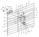
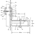
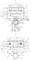
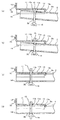
図1本願の第1の実施例を示す分解斜視図である。図2(a)は正面から見た図であり,(b)は背面から見た図である。図3は図2(a)におけるA−A線断面図である。図4はアンテナ支持杆の取付手順を示す。図5(a)に取付状態の側面から見た要部断面図と,(b)にこのときの上面から見た図を示す。図6に本発明の取付アングルの他の実施例を示す。図7は係止部とアンテナ支持杆の形状の異なる例を示す。
Hereinafter, an example of an embodiment embodying the present invention will be described in detail with reference to the drawings.
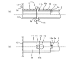
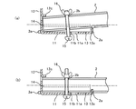
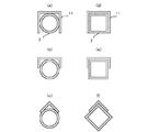
1 is an exploded perspective view showing a first embodiment of the present application. FIG. 2A is a view from the front, and FIG. 2B is a view from the back. FIG. 3 is a cross-sectional view taken along line AA in FIG. FIG. 4 shows a procedure for attaching the antenna support rod. FIG. 5 (a) shows a cross-sectional view of the main part viewed from the side in the mounted state, and FIG. FIG. 6 shows another embodiment of the mounting angle of the present invention. FIG. 7 shows an example in which the shape of the locking portion and the antenna support rod are different.
本願の発明は,図1,図2,図3に示す取付アングル10と挟持片30とから構成される。尚,以降の説明において方向を示す場合は,アンテナの取付方向を前方側として上側,下側,後方側を示す。
取付アングル10は金属製材料等の剛性を有する材料で折曲形成されており,前方側に形成した係止部11とこの係止部11の後方側において連設された取付部12とから形成されている。
この係止部11は前記取付部12から前方向に連設されており,断面略半月状に形成された湾曲部13と湾曲部13の両端部に連設された平板部14とから成る。
この湾曲部13の内側面,即ち下側にはアンテナのアーム2の後端部が取付けられるように,アーム2の外周面の曲率に合わせて湾曲形成してある。この係止部11の湾曲部13は,前記アンテナ支持杆の外面の全周に達しない範囲で一部若しくは連続的に当接すると共に,前記係止部11の長さ方向一側に開口部を形成するように屈曲形成され,少なくとも前記開口部の開口寸法は,前記アンテナ支持杆が当該アンテナ支持杆の長さ方向以外にも着脱可能に固着できる寸法から成るように形成されている。即ちこの開口寸法は,アンテナ支持杆の周径よりやや大きいか小さくなるように形成されている。
The invention of the present application is composed of the mounting
The mounting
The locking
The
更に湾曲部13の前方向端部には略中央に湾曲部13の内方向に切起した爪部13aが一体的に折曲形成されている。またアーム2には前記爪部13aと相対向する位置に係止孔2aが形成されており,係止部11の湾曲面13にアーム2を取付ける時に,前記爪部13aを前記係止孔2aに挿通さえながら取付けるように構成されている。
また,この係止部11には少なくとも1つの挿通孔11a(本願の実施例ではダルマ孔)が形成されており,加えて前記アーム2にもこの挿通孔11aと相対向する位置にアーム2を貫通する貫通孔2bを備えさせて,前記係止部11と前記アーム2との挿通孔に螺子棒15を挿通させて,この螺子にナット16を螺合することによって係止部11とアーム2を固着するように構成されている。
尚,前記平板部14は係止部の強度を高めるためのものである。
Further, a
In addition, at least one
The
次に取付部について説明する。この取付部12は略5角形をしており,この取付部12の下部に前記係止部11が直交するように一体的に折曲形成されている。尚,この取付部12の左右の両端部に切起部を前方方向に一体的に折曲形成させた補強部12aを備えることで取付部12の強度を高めるように形成しても良い。
更に取付部12の上端には,前記アンテナマストに当接させるための第1の折曲板部が前記取付部に立設するよう折曲形成されている。また,この第1の折曲板部の略中央部には,前記アンテナマストを受け入れる当接凹部21aが形成されている。
Next, the attachment portion will be described. The mounting
Further, a first bent plate portion for contacting the antenna mast is formed at the upper end of the mounting
更に,前記取付部12の中間位置には,当該取付部を折曲形成した第2の折曲板部22がアンテナマストに当接するように切起して形成されており,この第2の折曲板部の略中央部には,アンテナマストを受け入れる当接凹部22aが形成されている。
Further, a second
更に,前記第1の折曲板部21と前記第2の折曲板部22との間には,アンテナマスト側に突出成形した突出堤部23が形成されている。この突出堤部23は両端部に,この両端部の略中央から上方に向かって前記取付部にかけて連通させた長孔23a,23aが形成されている。
この長孔23a,23aは貫通孔であり,当該長孔にはU字ボルト24の折曲部24a,24aを,前記取付部12の前方向側から挿通させ,前記突出堤部23の内面には,前記U字ボルト24の連結部24bを収納するように構成されている。
Further, a protruding
The
このように係止部11と取付部12とからなる取付アングル10について更に説明する。
この取付アングル11の取付部12は,本願においては反射器3の反射器エレメント3b,3b,3bに溶接等の固着手段で持って取付けられている。また,反射器エレメント3bの替わりに反射器エレメント3bを保持する反射器支持杆3aに固着させても良い。
尚,上記実施例に示すように取付部12と,反射器支持杆3a若しくは反射器エレメント3bとを溶接等で固着する方法だけでなく,反射器3と取付部12とが着脱自在に固着する方法でも良い事は言うまでもない。
また,本願の実施例では前記第1の折曲板部21及び係止部11は,前記取付部12の上下端において夫々直角に相互に反対方向に折曲形成されている例を示したが,この実施例に限定されるものではなく,取付部21の任意の位置に形成しても良いことはいうまでも無い。この場合,係止部11は取付部21に溶接等の取付手段によって取付けても良い。 また,本願の実施例では第1の折曲板部及び第2の折曲板部を形成した例を示したが,取付部21の大きさに合わせて2ヶ所以上設けても良く実施例に限定されるものではない。
The
In the present application, the
In addition, as shown in the said Example, not only the method of adhering the
In the embodiment of the present application, the first
次に,挟持片30について説明する。この挟持片30は金属性材料等の剛性を有した材料を断面略コ字状に折曲形成されており,その両端部には挿通孔32,32が備えられている。本願の実施例では挿通孔32の一方は,挟持片30の短径の端部から連設された長孔に形成されており,他方は前記一方の長孔と同一方向に形成された長孔に形成されている。この挿通孔32,32は,前記取付部12の突出堤部23に設けた長孔23a,23aに挿通させた前記U字ボルト24の折曲部24a,24aの軸線と同一軸線上になるように配設されている。また挟持片の略中央にはアンテナマスト8を受け入れて当接するための湾曲部31(上側湾曲部31a,下側湾曲部31b)が形成されており,前記取付部12を構成する第1及び第2の折曲板部21,22の当接凹部21a,22aとでもって前記アンテナマスト8を挟持する。この抑圧方法としてはU字ボルト24の折曲部24a,24aに形成した螺子にナット25,25を螺合させることによって行う。
Next, the clamping
このように組み立てられたアンテナマスト取付金具について更に詳しく説明する。前記取付部に突出成形した突出堤部23に備えた長孔23a,23aは,前記突出堤部23の軸線を中心軸として,前記突出堤部の略中央から上方に向かって前記取付部12に達するように形成させてあることから,前記U字ボルト24の折曲部24aは,前記長孔の長さ方向に沿って,前記U字ボルト24の連結部24bの軸線を中心軸として,少なくとも90°回転自在となるように構成されている。つまりはアンテナマスト8に取付けた状態においては,前記挟持片30と取付部12とアンテナマストを挟持する位置に配設され,例えば製品の出荷時のように,アンテナマスト8に取付けていない状態においては,例えば前記挟持片が,前記取付部12がなす平面方向にU字ボルト24を回動させることによって,本願のアンテナマスト取付金具の外形がコンパクトに構成でき,梱包材への収納が容易になると共に,小型化による梱包材のコスト削減が可能となる。
尚,本願の実施例では,U字ボルト24が略水平方向から上方に向かって少なくとも90°回転自在となるように構成したが,これはアンテナマスト8への取付時に,U字ボルトがほぼ水平方向となるように位置させることができるので,アンテナマスト8への取付けを容易とするためであるが,これに限定されるものではなくU字ボルトが水平方向から上側にも下側にも略180°回動自在となるように,長孔を形成しても良い。
The antenna mast mounting bracket thus assembled will be described in more detail. The
In the embodiment of the present application, the
ここでアーム2を係止部13に取付ける手順について図4を用いて説明する。先ず(a)に示すように,湾曲部13に形成された挿通孔11aの大径孔と,アーム2の貫通孔2bにナット16によって上下方向に移動自在に螺着された螺子棒15の螺子頭とを対向配置させる。次に(b)に示す如く螺子棒15を上方向に押し上げて螺子頭を挿通孔11aに挿通させる。このように挿通させたなら(c)に示す如くアーム2を後方(図において左方)に移動させて,螺子軸を小径孔に嵌合させると共に,爪部13aがアーム2に形成された係止孔2aに挿入されるように取付ける。この状態において(d)のようにナット16を螺子棒15に螺合させて係止部11にアーム2を固着する。
こうして爪部13aと係止孔2aとの係合と,更に加えて挿通孔11aの大径孔と小径孔との連設部分には突起部11bを形成させることによって,ナット締め作業時や螺子棒が緩んだ時におけるアンテナ装置の落下防止に対する二重の安全対策がなされていると共に,アーム取付時の位置決め,螺子棒を確実に固定できるといった取付性のよい構成となっている。
図5に係止部にアンテナ支持杆を取付けた時の状態を示す。(a)は取付状態の側面から見た要部断面図であり,(b)はこのときの上面から見た図を示す。
尚,本願の実施例によれば爪部13aは係止部13の前方端部に一つ立設させているが,この実施例に限定されるものでなく,爪部を複数設けても良いし,その配置も係止部の任意の位置でも良いことは言うまでもない。また,爪部13aは係止部に対して直交させて一体的に形成され無くても良く,特に直交させることに限定されるものでなく,例えば図にも示したように,係止部13の端部からやや前方に傾かせて形成することによって,アンテナ支持杆の取付状態において,前記爪部の前方側面の一部が前記係止孔の孔端に当接するように構成するようにしても良いし,更に爪部13aの先端部を前方向に折り返したように形成して,アンテナ支持杆の取付状態において,この折り返し部分が係止孔の内側近傍の内壁と係合するようにしても良いなど,実施例に限定されるものではない。
Here, the procedure for attaching the
In this way, by engaging the engagement between the
FIG. 5 shows a state when the antenna support rod is attached to the locking portion. (A) is principal part sectional drawing seen from the side surface of the attachment state, (b) shows the figure seen from the upper surface at this time.
In addition, according to the embodiment of the present application, one
ここで各部の具体的な寸法を示すと,前記アンテナ支持杆の外径をA寸法とすると,アンテナ支持杆の長さがA寸法の10〜30倍において,前記係止部11は,長手方向の寸法がA寸法の1〜5倍,開口部の開口寸法がA寸法よりやや大きく形成され,前記爪部の幅はA寸法の0.04〜0.5倍,前記係止部の肉厚を含めた高さはA寸法の0.15〜1倍の大きさで前記係止部の前方側端部に立設させ,前記アンテナ支持杆の係止孔はA寸法の0.04〜0.5倍よりやや大きくなるように形成る。例えばアンテナ支持杆が22mmとすると,220〜660mmのアンテナ支持杆の場合,係止部11の長さは22〜110mm,係止部の開口寸法は22mmよりやや大きく形成され,爪部13aの幅は0.88〜11mm,前記係止部の肉厚を含めた高さは前記係止部の肉厚を含めて3.3〜22mmとなり,これに対応する係止孔の径は0.88〜11mmよりやや大きくなるように形成される。実験的にはアンテナ支持杆の太さは22mm,長さは400mmであり,係止部の長さは45mm,爪部の幅は5mm,爪部の高さは6.5mmであり,係止孔の径は6mmである。
尚,本発明の実施例では係止部11に湾曲部13を設けた例を示しているが,この実施例に限定されるものではなく,図7(a),(b),(d),(e)に示す如く,係止部の形状を断面略コ字状に形成しても良い。この場合はアンテナ支持杆は略四角形の場合にも,円形の場合にも対応可能である。また図7(c),(e)に示す如く,係止部の形状を断面略く字状に形成してもよい。この場合においてもアンテナ支持杆は,四角形及び円形の場合に対応可能である。
Here, specific dimensions of each part are shown. If the outer diameter of the antenna support rod is A, the length of the antenna support rod is 10 to 30 times the A dimension, and the locking
In addition, although the example which provided the
図6(a),(b)に取付アングル10の異なる実施例を示す。この実施例は係止部11の湾曲部13が上方に向かって開口するように構成されたものである。この実施例ではアンテナ支持杆2は係止部11上方から湾曲部に載置されて,上述の実施例と同様に螺子棒15とナット16とで固着されるのである。このときアンテナ支持杆2の後端部は,取付部12の一部を切り起した係止片12cと係止部11との間に係合すると共に,当該係止部11の先端部に形成した爪部13aがアンテナ支持杆2に設けた係止孔2aに挿入されることによって,アンテナ支持杆2の取付時に落下の危険等のない安定的な取付ができる。更には挿通孔11aに設けた突起部11bによって螺子棒が緩み難い構成となっており,信頼性の高い構成となっている。
6 (a) and 6 (b) show different embodiments of the mounting
このように本願の実施例によれば,アンテナ反射器3を前記取付アングル10とアンテナマスト8,少なくとも前記取付アングル10が前記アンテナ反射器の支持杆3aもしくは反射器を構成するエレメント3bに固着されることによって,前記取付アングル10の前方側の係止部11を,前記アンテナ支持杆2の後端部外面に取付けたときに,前記アンテナ支持杆2の軸線と前記アンテナマスト8の軸線とが直交交差するように配設されることになり,少なくとも前記アンテナ支持杆2の後端部はアンテナマスト8より前方側になるように配設されるので,前記アンテナ支持杆2と前記アンテナマスト8が相互に交叉するような位置に取付けられることが無く,前記アンテナ支持杆2の後端部がベランダ側に突出することが無く,ベランダを利用するユーザーにとっては邪魔になったり危険になったりすることのないアンテナマスト取付金具及び当該アンテナ取付金具を備えたアンテナ装置を提供できるのである。
また,アンテナ支持杆2を短く構成できることから,工場出荷時の荷姿が小さくなるので,言うまでもなく梱包材の材料が少なく,寸法形状を小さくすることになり,この結果,運送費が安くなり延いては製品のコストを低減することができるアンテナマスト取付金具及び当該アンテナマスト取付金具を備えたアンテナ装置を提供できるのである。
尚,本発明は上記実施の形態に限定されるものではなく,例えば挟持片は中央部を屈曲形成させた構成としても良い。また反射器支持杆の替わりに反射器エレメントに取付アングルを固着しても良いなど,本発明の趣旨を逸脱しない範囲で各部の構成を適宜に変更して実施することも可能である。
Thus, according to the embodiment of the present application, the
In addition, since the
In addition, this invention is not limited to the said embodiment, For example, a clamping piece is good also as a structure which bent the center part. In addition, the configuration of each part can be appropriately changed and implemented without departing from the spirit of the present invention, for example, a mounting angle may be fixed to the reflector element instead of the reflector support rod.
2…アンテナ支持杆,2a…係止孔,2b…貫通孔,3…反射器,3a…反射器支持杆,3b…反射エレメント,8…アンテナマスト,10…取付アングル,11…係止部,11a…挿通孔,11b…突起部,12…取付部,12a…補強部,13…湾曲部,13a…爪部,14…平板部,15…螺子棒,16…ナット,
21…第1の折曲板部,21a…当接凹部,22…第2の折曲板部,22a…当接凹部,23…突出堤部,23a…長孔,24…U字ボルト,24a…折曲部,24b…連結部,
25…ナット,31…湾曲部,32…挿通孔
2 ... Antenna support rod, 2a ... Locking hole, 2b ... Through hole, 3 ... Reflector, 3a ... Reflector support rod, 3b ... Reflective element, 8 ... Antenna mast, 10 ... Mounting angle, 11 ... Locking portion, 11a ... Insertion hole, 11b ... Projection part, 12 ... Mounting part, 12a ... Reinforcement part, 13 ... Curved part, 13a ... Claw part, 14 ... Flat plate part, 15 ... Screw rod, 16 ... Nut,
DESCRIPTION OF
25 ... nut, 31 ... curved portion, 32 ... insertion hole
Claims (10)
前方側に形成した係止部と,当該係止部の後方側において,前記係止部に連設された取付部であって,当該取付部に略直角に立設され,前記アンテナマストと当接するよう折曲形成された第1の折曲板部及び第2の折曲板部と,前記第1の折曲板部と前記第2の折曲板部との間に位置して,前記取付部の一部よりアンテナマスト側に突出成形した突出堤部と,この突出堤部の両端部に,この両端部の中央から前記取付部にかけて連通させた長孔と,からなる取付アングルと,
前記長孔に前記取付部の後方側から折曲部を挿入し,連結部を前記突出堤部の内面側に組込むことで,前記突出堤部を支点とし,前記長孔に沿って少なくとも90°回動自在となしたU字ボルトと,
前記U字ボルトの折曲部を両端部に挿通させると共に,前記アンテナマストに当接して,当該アンテナマストを前記取付アングルと挟持する挟持片と,
前記U字ボルトの折曲部の螺子に螺合させ,前記挟持片を前記取付アングルに近接するよう抑制するためのナットと,
からなり,
前記取付アングルの取付部は,アンテナ反射器を支持する反射器支持杆若しくは反射器エレメントと着脱自在に固着したことを特徴としたアンテナマスト取付金具。
In the antenna mast mounting bracket for attaching the antenna support rod to the antenna mast,
A locking portion formed on the front side and a mounting portion connected to the locking portion on the rear side of the locking portion, which is erected substantially at right angles to the mounting portion and contacts the antenna mast. The first bent plate portion and the second bent plate portion formed to be in contact with each other, and located between the first bent plate portion and the second bent plate portion, A mounting ridge formed by projecting a bulge protruding from the part of the mounting portion toward the antenna mast, and a long hole communicating with both ends of the protruding dam from the center of the both ends to the mounting portion;
A bent portion is inserted into the elongated hole from the rear side of the mounting portion, and a connecting portion is assembled on the inner surface side of the protruding dam portion, so that the protruding ridge portion serves as a fulcrum and is at least 90 ° along the elongated hole. A U-bolt that can rotate freely,
A bent piece for inserting the bent portion of the U-bolt into both ends and abutting the antenna mast to hold the antenna mast with the mounting angle;
A nut for screwing into a screw of the bent portion of the U-bolt and suppressing the clamping piece so as to be close to the mounting angle;
Consists of
The antenna mast mounting bracket, wherein the mounting portion of the mounting angle is detachably fixed to a reflector support rod or reflector element for supporting the antenna reflector.
The locking portion of the mounting angle includes at least one claw portion that is erected integrally with the locking portion, and includes an antenna support rod having a locking hole that is arranged to oppose the claw portion. 2. The antenna mast mounting bracket according to claim 1, wherein the antenna mast mounting bracket is configured to fit and attach the claw portion and the locking hole.
The mounting portion of the mounting angle of the antenna mast mounting bracket is disposed so that the axis of the antenna support rod intersects the axis of the antenna mast when the mounting portion is attached to the antenna support rod. The antenna mast mounting bracket according to claim 1 or 2.
4. The apparatus according to claim 1, wherein when the locking portion is attached to the antenna support rod, the axis line of the antenna support rod and the axis line of the antenna mast are arranged to intersect at right angles. 5. Antenna mast mounting bracket as described.
5. The antenna mast mounting device according to claim 1, wherein at least the mounting angle and the reflector support rod or the reflector element are fixed in advance.
The locking portion of the mounting angle abuts partly or continuously within a range that does not reach the entire circumference of the outer surface of the antenna support rod, and forms an opening on one side in the length direction of the locking portion. The opening dimension of at least the opening is formed so that the antenna support rod can be detachably fixed in a direction other than the length direction of the antenna support rod. The antenna mast mounting bracket according to any one of claims 1 to 5.
The antenna mast mounting bracket according to any one of claims 1 to 6, wherein the antenna support rod has a substantially circular shape or a substantially square shape.
When the outer diameter of the antenna support rod is A, the length of the antenna support rod is 10 to 30 times the A size. The claw part has a width of 0.04 to 0.5 times the A dimension, and the height including the thickness of the locking part is 0.15 to the A dimension. The antenna support rod is formed so as to be slightly larger than 0.04 to 0.5 times the dimension A, and is erected at the front end portion of the engagement portion with a size of 1 time. The antenna mast mounting bracket according to any one of claims 1 to 7, wherein the antenna mast mounting bracket is characterized.
9. The antenna according to claim 8, wherein, in the mounting angle, the first bent plate portion and the locking portion are bent in the opposite directions at right angles at the upper and lower ends of the mounting portion, respectively. Mast mounting bracket.
An antenna device using the antenna mast mounting bracket according to any one of claims 1 to 9.
Priority Applications (1)
| Application Number | Priority Date | Filing Date | Title |
|---|---|---|---|
| JP2004105480A JP4740552B2 (en) | 2004-03-31 | 2004-03-31 | Antenna mast mounting bracket and antenna device |
Applications Claiming Priority (1)
| Application Number | Priority Date | Filing Date | Title |
|---|---|---|---|
| JP2004105480A JP4740552B2 (en) | 2004-03-31 | 2004-03-31 | Antenna mast mounting bracket and antenna device |
Publications (2)
| Publication Number | Publication Date |
|---|---|
| JP2005295079A true JP2005295079A (en) | 2005-10-20 |
| JP4740552B2 JP4740552B2 (en) | 2011-08-03 |
Family
ID=35327553
Family Applications (1)
| Application Number | Title | Priority Date | Filing Date |
|---|---|---|---|
| JP2004105480A Expired - Fee Related JP4740552B2 (en) | 2004-03-31 | 2004-03-31 | Antenna mast mounting bracket and antenna device |
Country Status (1)
| Country | Link |
|---|---|
| JP (1) | JP4740552B2 (en) |
Cited By (4)
| Publication number | Priority date | Publication date | Assignee | Title |
|---|---|---|---|---|
| JP2008109456A (en) * | 2006-10-26 | 2008-05-08 | Maspro Denkoh Corp | Antenna device |
| JP2010074281A (en) * | 2008-09-16 | 2010-04-02 | Buffalo Inc | Directivity antenna |
| JP2012034187A (en) * | 2010-07-30 | 2012-02-16 | Tcm Corp | Mounting device of rod antenna |
| JP2012034188A (en) * | 2010-07-30 | 2012-02-16 | Tcm Corp | Mounting device of rod antenna |
Citations (10)
| Publication number | Priority date | Publication date | Assignee | Title |
|---|---|---|---|---|
| JPS5255144A (en) * | 1975-10-31 | 1977-05-06 | Toshiba Corp | Elevator |
| JPS5345845A (en) * | 1976-10-06 | 1978-04-25 | Yosakichi Hayashi | Rotary device for rotating bicycle chain wheel provided with rectangular shaft hole while eccentrically moving wheel |
| JPS55144404A (en) * | 1979-04-24 | 1980-11-11 | Toshiba Corp | Manufacture of discharge electrode for flat plate type ozonizer |
| JPS55144405A (en) * | 1979-04-25 | 1980-11-11 | Hitachi Ltd | Plate type ozonizer |
| JPS577210A (en) * | 1980-06-13 | 1982-01-14 | Sanshin Seisakusho:Kk | Method and apparatus for continuously and repeatedly washing filter material of filter machine |
| JPS57106313A (en) * | 1980-12-18 | 1982-07-02 | Furukawa Electric Co Ltd | Method of installing aerial transmission line |
| JPS59166505A (en) * | 1983-03-10 | 1984-09-19 | Kuraray Co Ltd | Dispersion stabilizer for suspension polymerization |
| JPH08279709A (en) * | 1996-05-22 | 1996-10-22 | Yagi Antenna Co Ltd | Antenna fixture |
| JP2000151233A (en) * | 1998-11-12 | 2000-05-30 | Dx Antenna Co Ltd | Veranda guard rail fixture for antenna |
| JP2005269252A (en) * | 2004-03-18 | 2005-09-29 | Maspro Denkoh Corp | Antenna mast mounting bracket and antenna device |
-
2004
- 2004-03-31 JP JP2004105480A patent/JP4740552B2/en not_active Expired - Fee Related
Patent Citations (10)
| Publication number | Priority date | Publication date | Assignee | Title |
|---|---|---|---|---|
| JPS5255144A (en) * | 1975-10-31 | 1977-05-06 | Toshiba Corp | Elevator |
| JPS5345845A (en) * | 1976-10-06 | 1978-04-25 | Yosakichi Hayashi | Rotary device for rotating bicycle chain wheel provided with rectangular shaft hole while eccentrically moving wheel |
| JPS55144404A (en) * | 1979-04-24 | 1980-11-11 | Toshiba Corp | Manufacture of discharge electrode for flat plate type ozonizer |
| JPS55144405A (en) * | 1979-04-25 | 1980-11-11 | Hitachi Ltd | Plate type ozonizer |
| JPS577210A (en) * | 1980-06-13 | 1982-01-14 | Sanshin Seisakusho:Kk | Method and apparatus for continuously and repeatedly washing filter material of filter machine |
| JPS57106313A (en) * | 1980-12-18 | 1982-07-02 | Furukawa Electric Co Ltd | Method of installing aerial transmission line |
| JPS59166505A (en) * | 1983-03-10 | 1984-09-19 | Kuraray Co Ltd | Dispersion stabilizer for suspension polymerization |
| JPH08279709A (en) * | 1996-05-22 | 1996-10-22 | Yagi Antenna Co Ltd | Antenna fixture |
| JP2000151233A (en) * | 1998-11-12 | 2000-05-30 | Dx Antenna Co Ltd | Veranda guard rail fixture for antenna |
| JP2005269252A (en) * | 2004-03-18 | 2005-09-29 | Maspro Denkoh Corp | Antenna mast mounting bracket and antenna device |
Cited By (4)
| Publication number | Priority date | Publication date | Assignee | Title |
|---|---|---|---|---|
| JP2008109456A (en) * | 2006-10-26 | 2008-05-08 | Maspro Denkoh Corp | Antenna device |
| JP2010074281A (en) * | 2008-09-16 | 2010-04-02 | Buffalo Inc | Directivity antenna |
| JP2012034187A (en) * | 2010-07-30 | 2012-02-16 | Tcm Corp | Mounting device of rod antenna |
| JP2012034188A (en) * | 2010-07-30 | 2012-02-16 | Tcm Corp | Mounting device of rod antenna |
Also Published As
| Publication number | Publication date |
|---|---|
| JP4740552B2 (en) | 2011-08-03 |
Similar Documents
| Publication | Publication Date | Title |
|---|---|---|
| JP7572743B2 (en) | Lighting equipment | |
| JP5324274B2 (en) | Antenna mounting device | |
| JP2005295079A (en) | Antenna mast mounting bracket and antenna device | |
| US20090179115A1 (en) | Retaining ring structure for fixing a satellite antenna | |
| JP4500568B2 (en) | Antenna mast mounting bracket and antenna device | |
| JP5222180B2 (en) | Mounting part, structure for assembling vertical and horizontal members by mounting part, and method for assembling the same | |
| JP2005268956A (en) | Antenna mast mounting bracket and antenna device | |
| JP4524574B2 (en) | Lens fixing structure in photoelectric sensor | |
| JP2005268955A (en) | Antenna mast mounting bracket and antenna device | |
| JP4628215B2 (en) | Antenna mounting structure | |
| JP2000151233A (en) | Veranda guard rail fixture for antenna | |
| JP5047866B2 (en) | Reflector antenna | |
| JP2010239348A (en) | Antenna mounting bracket | |
| JP3127558U (en) | Indoor and outdoor antenna | |
| JPH1022714A (en) | Mast holder folding structure for antenna | |
| JP4899332B2 (en) | Battery terminal | |
| JP3118676U (en) | Mounting device and flat display using the mounting device | |
| JP3106320B2 (en) | Parabolic antenna converter support | |
| JP4258844B2 (en) | Pole mounting attachment | |
| JP4927587B2 (en) | antenna | |
| JP4366296B2 (en) | Attachment body and screw fixing nut | |
| JP5572535B2 (en) | Yagi type antenna with auxiliary arm mounting structure | |
| JP2006174362A (en) | Antenna supporter | |
| JP3734811B2 (en) | Antenna device | |
| JP3046583U (en) | Antenna device |
Legal Events
| Date | Code | Title | Description |
|---|---|---|---|
| A621 | Written request for application examination |
Free format text: JAPANESE INTERMEDIATE CODE: A621 Effective date: 20070329 |
|
| A977 | Report on retrieval |
Free format text: JAPANESE INTERMEDIATE CODE: A971007 Effective date: 20091006 |
|
| A131 | Notification of reasons for refusal |
Free format text: JAPANESE INTERMEDIATE CODE: A131 Effective date: 20091030 |
|
| RD02 | Notification of acceptance of power of attorney |
Free format text: JAPANESE INTERMEDIATE CODE: A7422 Effective date: 20091201 |
|
| A521 | Written amendment |
Free format text: JAPANESE INTERMEDIATE CODE: A523 Effective date: 20091228 |
|
| A131 | Notification of reasons for refusal |
Free format text: JAPANESE INTERMEDIATE CODE: A131 Effective date: 20100406 |
|
| A521 | Written amendment |
Free format text: JAPANESE INTERMEDIATE CODE: A523 Effective date: 20100607 |
|
| A01 | Written decision to grant a patent or to grant a registration (utility model) |
Free format text: JAPANESE INTERMEDIATE CODE: A01 Effective date: 20110412 |
|
| A61 | First payment of annual fees (during grant procedure) |
Free format text: JAPANESE INTERMEDIATE CODE: A61 Effective date: 20110502 |
|
| R150 | Certificate of patent or registration of utility model |
Free format text: JAPANESE INTERMEDIATE CODE: R150 |
|
| FPAY | Renewal fee payment (event date is renewal date of database) |
Free format text: PAYMENT UNTIL: 20140513 Year of fee payment: 3 |
|
| R250 | Receipt of annual fees |
Free format text: JAPANESE INTERMEDIATE CODE: R250 |
|
| R250 | Receipt of annual fees |
Free format text: JAPANESE INTERMEDIATE CODE: R250 |
|
| R250 | Receipt of annual fees |
Free format text: JAPANESE INTERMEDIATE CODE: R250 |
|
| LAPS | Cancellation because of no payment of annual fees |