JP2005294986A - Acoustic vibration generation device - Google Patents
Acoustic vibration generation device Download PDFInfo
- Publication number
- JP2005294986A JP2005294986A JP2004103909A JP2004103909A JP2005294986A JP 2005294986 A JP2005294986 A JP 2005294986A JP 2004103909 A JP2004103909 A JP 2004103909A JP 2004103909 A JP2004103909 A JP 2004103909A JP 2005294986 A JP2005294986 A JP 2005294986A
- Authority
- JP
- Japan
- Prior art keywords
- piezoelectric
- elastic plate
- acoustic vibration
- generating element
- vibration generating
- Prior art date
- Legal status (The legal status is an assumption and is not a legal conclusion. Google has not performed a legal analysis and makes no representation as to the accuracy of the status listed.)
- Pending
Links
- 239000000919 ceramic Substances 0.000 claims abstract description 19
- 210000000988 bone and bone Anatomy 0.000 abstract description 5
- 239000000463 material Substances 0.000 description 18
- 238000005452 bending Methods 0.000 description 10
- 230000001133 acceleration Effects 0.000 description 5
- 229910001369 Brass Inorganic materials 0.000 description 4
- 239000010951 brass Substances 0.000 description 4
- 230000005684 electric field Effects 0.000 description 4
- 230000000149 penetrating effect Effects 0.000 description 4
- 230000005484 gravity Effects 0.000 description 3
- 238000000034 method Methods 0.000 description 3
- 210000000860 cochlear nerve Anatomy 0.000 description 2
- 230000000052 comparative effect Effects 0.000 description 2
- 239000002184 metal Substances 0.000 description 2
- 229910052751 metal Inorganic materials 0.000 description 2
- 230000010287 polarization Effects 0.000 description 2
- 230000002238 attenuated effect Effects 0.000 description 1
- 239000000470 constituent Substances 0.000 description 1
- 238000006073 displacement reaction Methods 0.000 description 1
- 230000000694 effects Effects 0.000 description 1
- 229920006332 epoxy adhesive Polymers 0.000 description 1
- 238000002474 experimental method Methods 0.000 description 1
- 230000014509 gene expression Effects 0.000 description 1
- 239000007943 implant Substances 0.000 description 1
- 230000003993 interaction Effects 0.000 description 1
- 210000001595 mastoid Anatomy 0.000 description 1
- 238000005259 measurement Methods 0.000 description 1
- 230000001902 propagating effect Effects 0.000 description 1
- 229920002545 silicone oil Polymers 0.000 description 1
- 229910052709 silver Inorganic materials 0.000 description 1
- 239000004332 silver Substances 0.000 description 1
- 210000003625 skull Anatomy 0.000 description 1
- 238000004804 winding Methods 0.000 description 1
Images


Landscapes
- Piezo-Electric Transducers For Audible Bands (AREA)
- Details Of Audible-Bandwidth Transducers (AREA)
Abstract
Description
本発明は、電気信号を音響振動に変換して頭骨や腕に伝搬させ、それを聴覚神経で聴取する目的の骨伝導スピーカや、パネルもしくは筐体を機械的に励振して音響を発生するスピーカに用いるのに好適な、小型の音響振動発生素子に関するものである。 The present invention relates to a bone conduction speaker for converting an electrical signal into acoustic vibration and propagating it to the skull or arm and listening to it with an auditory nerve, or a speaker for generating sound by mechanically exciting a panel or housing. The present invention relates to a small-sized acoustic vibration generating element suitable for use in the above.
従来、音響分野での電気−機械トランスデューサとしては、主に電磁式が用いられ、ダイナミックスピーカと同じ原理のコイルを流れる電流とマグネットとの相互作用で発生する電磁力を機械振動に変えるもので、長い歴史を持ち、現在も音響の振動発生素子の主流として利用されている。しかし、電磁方式の発生力は電磁力であり、電流を必要とするが、巻線の有する抵抗でエネルギー損失を生じ、電源から供給されるエネルギーの大半はジュール熱として散失し、音響エネルギーとして使用される分はわずかに1%にすぎない。また、低音領域では低インピーダンスの為に、電流が過剰になりやすく電源側の負荷が大きく、結果的に低音域では出力を制限せざるを得ない為に、低音の音響出力不足になりやすいという欠点があった。 Conventionally, as an electro-mechanical transducer in the acoustic field, an electromagnetic type is mainly used, and an electromagnetic force generated by an interaction between a magnet and a current flowing through a coil having the same principle as a dynamic speaker is changed to a mechanical vibration. It has a long history and is still used as the mainstream of acoustic vibration generating elements. However, the generated force of the electromagnetic method is electromagnetic force and requires current, but energy loss is caused by the resistance of the winding, and most of the energy supplied from the power source is lost as Joule heat and used as acoustic energy Only 1% is done. In addition, because the impedance is low in the bass range, the current tends to be excessive, the load on the power supply side is large, and as a result, the output must be limited in the bass range. There were drawbacks.
一方、少数ではあるが、圧電素子を用いた音響用トランスデユーサも特定の分野で用いられてきた。この場合は圧電発音体として多く用いられ金属板と圧電材料を貼りあわせた圧電モノモルフ構造を用いているが、実用域のサイズでは基本的に共振周波数が1kHz以上になる為に、共振周波数より下の低音域の再生が不充分になり易い欠点があった。また、振動系の機械的品質係数Qmが高い為に特定の周波数で強調されたり、逆に減衰したりするために自然な音の再生ができないという欠点もあり、リンガーやツィータらの限定された用途で用いられた。これらの圧電型スピーカの低音域での弱点を克服するためのいくつかの提案も出されているが、電磁型に比肩する領域の低音を実現できている訳ではない(特許文献1及び2参照)。
On the other hand, although it is a small number, acoustic transducers using piezoelectric elements have also been used in specific fields. In this case, a piezoelectric monomorph structure that is often used as a piezoelectric sounding body and a metal plate and a piezoelectric material are bonded together is used. However, since the resonance frequency is basically 1 kHz or more in the practical size, it is lower than the resonance frequency. There is a drawback that the reproduction of the low frequency range is likely to be insufficient. In addition, since the mechanical quality factor Qm of the vibration system is high, it is emphasized at a specific frequency or is attenuated on the contrary, so that natural sound cannot be reproduced. Used in applications. Several proposals have been made to overcome the weaknesses of these piezoelectric speakers in the low frequency range, but low frequency in a region comparable to the electromagnetic type has not been realized (see
骨伝導スピーカについても圧電方式の試みがなされている(例えば、特許文献3及び4参照)。これは使用者の頭部に装着して使用するのが一般的であり、使用者の負荷を軽減するため、骨伝導スピーカには小型化、軽量化が強く求められており、音響振動発生素子も小型にする必要があるが、音響振動発生素子を小型にすると、基本的には素子の共振周波数が増大し出力が高域の周波数にシフトして所望の音響出力だせない問題点がある。また、近年の携帯型電子機器の普及に伴い省電力が重要な課題となっており、圧電タイプの音響スピーカが注目されている。ここでも音響振動発生素子も小型にする必要があり、音響特性の実現と小型化の両立が重要な課題となる。
A piezoelectric method has also been attempted for a bone conduction speaker (see, for example,
音響振動発生用のバイモルフ振動子については、その構成と音響性能の関係については基本的なところは数式的にも十分に整理されているため、以下に若干の数式を用いて説明する。まず、音響出力の周波数特性に関与する素子の共振周波数frについて数1の関係で構成要素と関係する。
Regarding the bimorph vibrator for generating acoustic vibration, the basic relationship between the configuration and the acoustic performance is well organized mathematically, and will be described below using some mathematical expressions. First, the relationship between components in relation to the
数1中のLは振動子の長さであり、小型化のために短くしようとすると他の要素で補正しない限り急激に共振周波数を上げて周波数特性を高域のほうに持ち上げる傾向がある。αnは振動姿態で決まる定数であり、以後の説明では触れない。
L in
数1中のKは、圧電材料とシム材料(弾性板)の厚みおよび弾性係数で決まる曲げの弾性係数である。この関係を数2に示す。
K in
ここで、wは素子の幅、EsとEcはシム材料と圧電材料の弾性係数であり、2tsとtcはシムと圧電材料の厚みを示す。幅wが決まるとKは構成材料の弾性係数と厚みに支配される。数1中のρSは単位長さあたりの重さを示し、数3で示される。ここで、ρc、ρsは、それぞれ圧電材料とシム材料の比重を示す。
Here, w is the width of the element, E s and E c is the modulus of elasticity of the shim material and the piezoelectric material, 2t s and t c indicates the thickness of the shim and piezoelectric material. When the width w is determined, K is governed by the elastic modulus and thickness of the constituent material. ΡS in
次に、音響振動発生素子の駆動力の源である、電界に応じて発生する曲げモーメントMeについて説明する。圧電バイモルフ素子に電圧を印加されたときに曲げモーメントMeが発生して素子が屈曲変形して振動する。曲げモーメントMeと構成要素との関係は数4で示される。数4中でeは圧電材料の圧電定数で電界に応じて発生する応力の度合いを示し、Vは印加する電圧を示している。 Next, the source of the driving force of the acoustic vibration generating element, the bending moment M e explained generated in response to an electric field. When a voltage is applied to the piezoelectric bimorph element, a bending moment Me is generated, and the element is bent and vibrated. The relationship between the bending moment Me and the component is expressed by Equation 4. In Equation 4, e is the piezoelectric constant of the piezoelectric material, indicating the degree of stress generated according to the electric field, and V indicating the voltage to be applied.
曲げモーメントMeが大きいほど発生する変位が大きくなり、結果として振動速度、振動の加速度が大きくなる。音響振動発生素子の駆動力Fbは素子の長さ方向についての微小区間dxの重量ρSdxとその部分の加速度αの積で得られる慣性力を全区間について積分した値として求めることができ数5に示した。数5のa(x)は各部分の振幅を示し、振動姿態や周波数に応じて変化するが、大きな曲げモーメントは必然的に大きな振幅につながり、結果として大きな駆動力の発生に寄与する。
The greater the bending moment Me , the greater the displacement that occurs, resulting in a greater vibration speed and vibration acceleration. The driving force Fb of the acoustic vibration generating element can be obtained as a value obtained by integrating the inertial force obtained by the product of the weight ρSdx of the minute section dx in the length direction of the element and the acceleration α of the part, over the entire section. Indicated. In
数1〜数5の数式的な関係を踏まえ、できる限り小型で所望の周波数特性を満足し、高出力(大きな駆動力)の音響振動発生素子を得る構成方法は、諸量の関係から以下が考えられる。
Based on the mathematical relationships of
1)小型化に伴う周波数の増大を防ぐ方策
・ 曲げ弾性係数を下げる
→シム(弾性板)、圧電材料のヤング率下げる
→シム、圧電材料の厚みを薄くする
・ 単位長あたりの重量を上げる
→シム、圧電材料の厚みを上げる
→シム、圧電材料の比重を大きくする
2)大きな出力を得る
→高い電圧を印加する
→高い圧電定数の材料を使う
→幅を広げる
→厚みを厚くする
1) Measures to prevent increase in frequency due to miniaturization ・ Lower the flexural modulus
→ Shim (elastic plate), lowering the Young's modulus of piezoelectric material → Shim, reducing the thickness of piezoelectric material
・ Increase the weight per unit length → Increase the thickness of shims and piezoelectric materials
→ Increase the specific gravity of shims and piezoelectric materials 2) Obtain a large output → Apply a high voltage → Use a material with a high piezoelectric constant → Increase the width → Increase the thickness
以上の諸策についてさらに吟味すると、十分に選択されて採用された圧電材料は変更の可能性が乏しく、また駆動条件や、幅についても+の方向はありえないために現実的な策のみを抜粋していくと
1)小型化に伴う周波数の増大を防ぐ必要
・ 曲げ弾性係数を下げる
→シム(弾性板)のヤング率下げる
→シムの厚みを薄くする
・ 単位長あたりの重量を上げる
→シムの厚みを上げる
→シムの比重を大きくする
2)大きな出力を得る
→圧電材料またはシムの厚みを厚くする
以上の策が残るが一部には相反する効果の策もあり、実験を踏まえて到達した結論としてシムは許される範囲で厚くし、機械的には撓みやすい構造を持たせ見かけ上の弾性係数を下げること、およびシムの重量は極力下げないことで目的が達成できることを見出した。以上は圧電バイモルフについて説明したが、この原理は圧電モノモルフ構造にも適用できることは言うまでもない。
Further examination of the above measures shows that the piezoelectric materials that have been selected and adopted are unlikely to change, and the driving conditions and width cannot be positive, so only realistic measures are extracted. 1) Necessary to prevent increase in frequency due to downsizing ・ Lower flexural modulus
→ Lower Young's modulus of shim (elastic plate) → Reduce shim thickness
・ Increase the weight per unit length → Increase the thickness of the shim → Increase the specific gravity of the shim 2) Obtain a large output → There are more measures than increasing the thickness of the piezoelectric material or shim, but some conflicting effects As a conclusion that was reached based on experiments, the shim should be as thick as possible, have a mechanically flexible structure, reduce the apparent elastic modulus, and reduce the weight of the shim as much as possible. And found that the purpose can be achieved. Although the piezoelectric bimorph has been described above, it goes without saying that this principle can also be applied to a piezoelectric monomorph structure.
本発明は、上記の問題点を解決するためになされたもので、圧電バイモルフ構造または圧電モノモルフ構造の音響振動発生素子を骨伝導スピーカや小型のパネルスピーカ等への応用する場合において、小型で音響出力が大きな音響振動発生素子の提供を目的とするものである。 The present invention has been made in order to solve the above-described problems. When an acoustic vibration generating element having a piezoelectric bimorph structure or a piezoelectric monomorph structure is applied to a bone conduction speaker, a small panel speaker, etc., the present invention is small and acoustic. The object is to provide an acoustic vibration generating element having a large output.
本発明によれば、表裏面をメタライズした圧電セラミックス矩形板と弾性板を張り合わせた圧電バイモルフ構造または圧電モノモルフ構造の音響振動発生素子において、前記弾性板は長さ方向に直交する複数の厚み方向への切込みを有することを特徴とする音響振動発生素子が得られる。 According to the present invention, in the acoustic vibration generating element having a piezoelectric bimorph structure or a piezoelectric monomorph structure in which a piezoelectric ceramic rectangular plate whose front and back surfaces are metallized and an elastic plate are bonded together, the elastic plate extends in a plurality of thickness directions orthogonal to the length direction. An acoustic vibration generating element characterized by having a notch is obtained.
また、本発明によれば、表裏面をメタライズした圧電セラミックス矩形板と弾性板を張り合わせた圧電モノモルフ構造または圧電バイモルフ構造の音響振動発生素子において、前記弾性板は長さ方向に直交し、厚さ方向に貫通し、幅方向に貫通しない複数の切込み部を有することを特徴とする音響振動発生素子が得られる。 According to the invention, in the acoustic vibration generating element having a piezoelectric monomorph structure or a piezoelectric bimorph structure in which a piezoelectric ceramic rectangular plate whose front and back surfaces are metallized and an elastic plate are bonded together, the elastic plate is orthogonal to the length direction and has a thickness. An acoustic vibration generating element characterized by having a plurality of cut portions penetrating in the direction and not penetrating in the width direction is obtained.
前述のとおり、圧電セラミックス矩形板と弾性板を張り合わせた圧電モノモルフ構造または圧電バイモルフ構造において、弾性板の長さ方向に直交して複数の切込み部を構成することで、圧電セラミックス矩形板の厚さは変えずに、弾性板の厚さを厚くしても、音響振動発生素子の曲げ弾性係数が大きくならないので、周波数特性に影響せず、曲げモーメントが大きく、音響出力が大きな骨伝導用やパネルスピーカ用の音響振動発生素子の提供が可能である。 As described above, in the piezoelectric monomorph structure or the piezoelectric bimorph structure in which the piezoelectric ceramic rectangular plate and the elastic plate are bonded together, the thickness of the piezoelectric ceramic rectangular plate is configured by forming a plurality of cut portions perpendicular to the length direction of the elastic plate. Even if the elastic plate is made thick without changing the bending elastic modulus of the acoustic vibration generating element does not increase, the frequency characteristics are not affected, the bending moment is large, and the acoustic output is large. An acoustic vibration generating element for a speaker can be provided.
以下に、本発明の実施の形態について、図1〜図3を参照しながら詳細に説明する。 Hereinafter, embodiments of the present invention will be described in detail with reference to FIGS.
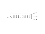
図1は、本発明の弾性板の長さ方向に直交する複数の切込みを有する弾性板を用いた圧電バイモルフ構造の音響振動発生素子の厚さ方向の断面図である。図2は、溝部を形成した弾性板の斜視図で、図2(a)は弾性板の片面に溝部を形成した斜視図、図2(b)は弾性板の両面に溝部を形成した斜視図である。また、図3は、長さ方向に直交し、厚さ方向に貫通し、幅方向に貫通しない複数の切込み部を形成した弾性板の斜視図で、図3(a)は、同一側面から切込み部を形成した弾性板の斜視図、図3(b)は、対向する側面から交互に切り込み部を形成した弾性板の斜視図、図3(c)は、側面に貫通しない切り込み部を形成した弾性板の斜視図である。 FIG. 1 is a cross-sectional view in the thickness direction of an acoustic vibration generating element having a piezoelectric bimorph structure using an elastic plate having a plurality of cuts orthogonal to the length direction of the elastic plate of the present invention. 2A and 2B are perspective views of the elastic plate in which the groove portion is formed, FIG. 2A is a perspective view in which the groove portion is formed on one surface of the elastic plate, and FIG. 2B is a perspective view in which the groove portion is formed on both surfaces of the elastic plate. It is. FIG. 3 is a perspective view of an elastic plate formed with a plurality of cut portions that are orthogonal to the length direction, penetrate in the thickness direction, and do not penetrate in the width direction. FIG. FIG. 3B is a perspective view of an elastic plate in which cut portions are alternately formed from opposite side surfaces, and FIG. 3C is a view in which cut portions that do not penetrate are formed on the side surfaces. It is a perspective view of an elastic board.
図1に示すように、2枚の表裏面をメタライズした圧電セラミックス矩形板1及び2が金属等の弾性板3の両面に接着した構造体で、弾性板3には矩形板の長さ方向に直交する複数の溝部4が形成してなる圧電バイモルフ構造の音響振動発生素子で、その曲げ弾性係数Kは、前述の通り、圧電セラミックス矩形板及び弾性板の幅w、及びそれぞれの厚さtc、2tsとそれぞれの弾性係数Ec、Esに支配され、前述の数1で表現される。
As shown in FIG. 1, piezoelectric ceramic
数1において、弾性板に溝部や切込み部を設けることは、物理的には数1において弾性板の弾性係数Esを小さくすることに該当し、音響振動発生素子の音響出力を大きくするために弾性板の厚さtsを厚くすることと弾性板に溝部や切込み部を設けることは、積の関係にある。従って、弾性板に溝部や切込み部を設けることにより、音響振動発生素子の曲げ弾性係数Kを大きくしないで、音響出力を大きくすることが可能となる。
In
以下、本発明の実施の形態を実施例を基に説明する。 Hereinafter, embodiments of the present invention will be described based on examples.
弾性板の厚み方向に切り込みを設けた試作例
NECトーキン製圧電セラミックス(商品名ネペック10)を用いた長さ32mm、幅8mm、厚さ0.15mmの圧電セラミックス矩形板2枚の表裏面に銀電極を焼付け、温度100℃のシリコーンオイル中で、150Vの直流電圧を印加し分極し、外形寸法が同じで厚みが150μmの真鍮製の弾性板3の両面にエポキシ系接着剤で貼り合わせた圧電バイモルフ構造の音響振動発生素子を試作した。予め、弾性板3には、ダイシングソーを用いて、図2(b)に示したような、表裏面に長さ方向に直交する幅50μm、深さ50μmの溝部5を1mmピッチで複数加工した。おのおのの圧電セラミックス矩形板について弾性板と両面のセラミックの外面にリード線を設け、一方の圧電セラミックス矩形板に分極方向と同じ電界が加わる場合に、他方の圧電セラミックス矩形板には分極方向と逆の電界が加わるように結線した。
Prototyping example with cuts in the thickness direction of the elastic plate NEC TOKIN's piezoelectric ceramics (trade name Nepec 10) are used to make silver on the front and back surfaces of two rectangular piezoelectric ceramic plates 32 mm long, 8 mm wide, and 0.15 mm thick. Electrodes were baked and applied with a direct current voltage of 150 V in silicone oil at a temperature of 100 ° C. and polarized, and the piezoelectric material was bonded to both surfaces of a brass
比較のために、同じ圧電セラミックス矩形板と溝加工のない厚さ50μmの真鍮製の弾性板を接着して、圧電バイモルフ構造の音響振動発生素子を試作した。 For comparison, an acoustic vibration generating element having a piezoelectric bimorph structure was prototyped by bonding the same piezoelectric ceramic rectangular plate and a brass elastic plate having a thickness of 50 μm without groove processing.
弾性板に幅方向に切込み部を設けた試作例
実施例1と同じ圧電セラミックス矩形板2枚と、外形寸法が同じで厚みが150μmの真鍮製の弾性板3を用いて、圧電バイモルフ構造の音響振動発生素子を試作した。予め、弾性板3には、ダイシングソーを用いて、図3(b)に示したような、長さ方向に直交する幅100μm、長さ7mmの切込み部7を1mmピッチで複数加工した。
Example of Prototype with Cuts in the Width Direction of Elastic Plate Using two piezoelectric ceramic rectangular plates as in Example 1 and a brass
比較のために、同じ圧電セラミックス矩形板と溝加工のない厚さ50μmの真鍮製の弾性板を接着して、圧電ユニモルフ構造の音響振動発生素子を試作した。 For comparison, an acoustic vibration generating element having a piezoelectric unimorph structure was prototyped by bonding the same piezoelectric ceramic rectangular plate and an elastic plate made of brass having a thickness of 50 μm without groove processing.
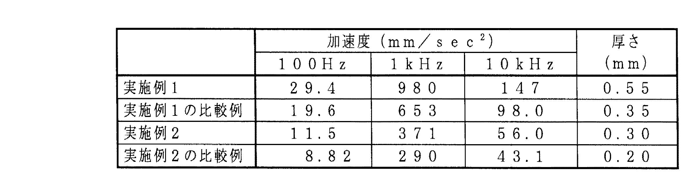
次に、試作した音響振動発生素子の音響出力を定量的に確認する為に、人工内耳(B&K社製 Artificial Mastoid Type 4930)を用いて人体の聴覚神経に相当する位置での加速度を測定した。測定結果を表1に示した。 Next, in order to quantitatively confirm the acoustic output of the prototyped acoustic vibration generating element, acceleration at a position corresponding to the auditory nerve of the human body was measured using a cochlear implant (Artificial Mastoid Type 4930 manufactured by B & K). The measurement results are shown in Table 1.
表1から明らかなように、実施例1では、音響振動発生素子の厚さが比較例より約1.6倍大きくなり、音響出力の加速度も約1.5倍大きくなっている。また、実施例2でも、音響振動発生素子の厚さが比較例より約1.33倍大きくなり、音響出力の加速度も約1.3倍大きくなっている。ところが、共振周波数は、それぞれ620Hzと630Hz(溝あり)で、厚みの割りに周波数の増大が抑制されていることがわかる。 As is clear from Table 1, in Example 1, the thickness of the acoustic vibration generating element is about 1.6 times larger than that of the comparative example, and the acceleration of the acoustic output is also about 1.5 times larger. In Example 2, the thickness of the acoustic vibration generating element is about 1.33 times larger than that of the comparative example, and the acceleration of the acoustic output is about 1.3 times larger. However, it can be seen that the resonance frequencies are 620 Hz and 630 Hz (with grooves), respectively, and the increase in frequency is suppressed for the thickness.
1,2 圧電セラミックス矩形板
3 弾性板
4,5 溝部
6,7,8 切込み部
1, 2 Piezoelectric ceramic
Claims (2)
Priority Applications (1)
| Application Number | Priority Date | Filing Date | Title |
|---|---|---|---|
| JP2004103909A JP2005294986A (en) | 2004-03-31 | 2004-03-31 | Acoustic vibration generation device |
Applications Claiming Priority (1)
| Application Number | Priority Date | Filing Date | Title |
|---|---|---|---|
| JP2004103909A JP2005294986A (en) | 2004-03-31 | 2004-03-31 | Acoustic vibration generation device |
Publications (1)
| Publication Number | Publication Date |
|---|---|
| JP2005294986A true JP2005294986A (en) | 2005-10-20 |
Family
ID=35327473
Family Applications (1)
| Application Number | Title | Priority Date | Filing Date |
|---|---|---|---|
| JP2004103909A Pending JP2005294986A (en) | 2004-03-31 | 2004-03-31 | Acoustic vibration generation device |
Country Status (1)
| Country | Link |
|---|---|
| JP (1) | JP2005294986A (en) |
Cited By (3)
| Publication number | Priority date | Publication date | Assignee | Title |
|---|---|---|---|---|
| CN102647656A (en) * | 2012-04-21 | 2012-08-22 | 瑞声声学科技(深圳)有限公司 | Sound device |
| JP2015055585A (en) * | 2013-09-13 | 2015-03-23 | 積水化学工業株式会社 | Piezoelectric vibration sensor |
| JP2018056162A (en) * | 2016-09-26 | 2018-04-05 | 京セラ株式会社 | Piezoelectric actuator |
-
2004
- 2004-03-31 JP JP2004103909A patent/JP2005294986A/en active Pending
Cited By (3)
| Publication number | Priority date | Publication date | Assignee | Title |
|---|---|---|---|---|
| CN102647656A (en) * | 2012-04-21 | 2012-08-22 | 瑞声声学科技(深圳)有限公司 | Sound device |
| JP2015055585A (en) * | 2013-09-13 | 2015-03-23 | 積水化学工業株式会社 | Piezoelectric vibration sensor |
| JP2018056162A (en) * | 2016-09-26 | 2018-04-05 | 京セラ株式会社 | Piezoelectric actuator |
Similar Documents
| Publication | Publication Date | Title |
|---|---|---|
| JP3958739B2 (en) | Acoustic vibration generator | |
| EP3994734B1 (en) | Piezoelectric transducer for tympanic membrane | |
| US7822215B2 (en) | Bone-conduction hearing-aid transducer having improved frequency response | |
| JP5558577B2 (en) | Piezoelectric vibration device and portable terminal using the same | |
| JP4662072B2 (en) | Piezoelectric acoustic element, acoustic device, and portable terminal device | |
| JP4761459B2 (en) | Piezoelectric vibration unit and piezoelectric speaker | |
| TW200428770A (en) | Piezoelectric vibrating plate, piezoelectric apparatus using piezoelectric vibrating plate, and portable phone and electronic device using piezoelectric apparatus | |
| JPWO2008146678A1 (en) | Piezoelectric actuator and electronic device | |
| WO2007083497A1 (en) | Piezoelectric actuator and electronic device | |
| WO2009141912A1 (en) | Earphone apparatus | |
| JP2006238072A (en) | Acoustic vibration generating piezoelectric bimorph element | |
| GB2496070A (en) | Ultrasonic wave-generating device | |
| JP2006229647A (en) | Acoustic vibrator for bone conduction | |
| JP2005311415A (en) | Acoustic vibration generation element | |
| JP7617977B2 (en) | Enhanced actuator for distributed mode loudspeakers. | |
| JP6319678B2 (en) | Piezoelectric speaker | |
| JP5934145B2 (en) | Mobile device | |
| JP2005294986A (en) | Acoustic vibration generation device | |
| EP4099715B1 (en) | Actuator for distributed mode loudspeaker with extended damper, mobile device and system including the same | |
| JP3587519B2 (en) | Piezoelectric transducer | |
| JP2007228610A (en) | Acoustic vibration generating element | |
| JP6514079B2 (en) | Sound generator | |
| JP2006352464A (en) | Acoustic vibration generating element | |
| JP2007221532A (en) | Acoustic vibration generating element | |
| JP2007036530A (en) | Piezoelectric device for generating acoustic signals |
Legal Events
| Date | Code | Title | Description |
|---|---|---|---|
| A131 | Notification of reasons for refusal |
Effective date: 20070606 Free format text: JAPANESE INTERMEDIATE CODE: A131 |
|
| A521 | Written amendment |
Free format text: JAPANESE INTERMEDIATE CODE: A523 Effective date: 20070803 |
|
| A131 | Notification of reasons for refusal |
Effective date: 20070829 Free format text: JAPANESE INTERMEDIATE CODE: A131 |
|
| A02 | Decision of refusal |
Free format text: JAPANESE INTERMEDIATE CODE: A02 Effective date: 20071226 |