JP2005294927A - Video doorphone system - Google Patents

Video doorphone system Download PDF

Info

Publication number
JP2005294927A
JP2005294927A JP2004103025A JP2004103025A JP2005294927A JP 2005294927 A JP2005294927 A JP 2005294927A JP 2004103025 A JP2004103025 A JP 2004103025A JP 2004103025 A JP2004103025 A JP 2004103025A JP 2005294927 A JP2005294927 A JP 2005294927A
Authority
JP
Japan
Prior art keywords
image
unit
entrance
call
camera
Prior art date
Legal status (The legal status is an assumption and is not a legal conclusion. Google has not performed a legal analysis and makes no representation as to the accuracy of the status listed.)
Granted
Application number
JP2004103025A
Other languages
Japanese (ja)
Other versions
JP4575694B2 (en
Inventor
Kazuki Niwa
一樹 丹羽
Kazumi Kitagawa
和美 北川
Current Assignee (The listed assignees may be inaccurate. Google has not performed a legal analysis and makes no representation or warranty as to the accuracy of the list.)
Aiphone Co Ltd
Original Assignee
Aiphone Co Ltd
Priority date (The priority date is an assumption and is not a legal conclusion. Google has not performed a legal analysis and makes no representation as to the accuracy of the date listed.)
Filing date
Publication date
Application filed by Aiphone Co Ltd filed Critical Aiphone Co Ltd
Priority to JP2004103025A priority Critical patent/JP4575694B2/en
Publication of JP2005294927A publication Critical patent/JP2005294927A/en
Application granted granted Critical
Publication of JP4575694B2 publication Critical patent/JP4575694B2/en
Anticipated expiration legal-status Critical
Expired - Lifetime legal-status Critical Current

Links

Images

Abstract

<P>PROBLEM TO BE SOLVED: To improve crime prevention performance by notifying the presence of a suspicious person who is undesirable for residents to not only interior master units in dwellings but also to third parties such as portable terminals outside the dwellings or the dedicated service center of a security company to enable a prompt action, and enable immediate transfer of images in an emergency. <P>SOLUTION: A still images or a moving image picked up with a camera of an entrance slave unit or a sensor camera 2 to be connected to an interior master unit is transferred to the portable terminal 4 or to the dedicated service center 5 of the security company via a radio communication network 7 or a wired communication network 8 and the Internet 9 by an operation of a communication transfer button 46 of the interior master unit 3 with which a call from the entrance slave set 1 is notified and a call is made while visually checking a static image or a moving image picked up with the camera 12 of the entrance slave unit by a monitor 34, and the presence of the suspicious person who is undesirable for residents is notified to the outside of the dwellings. <P>COPYRIGHT: (C)2006,JPO&NCIPI

Description

本発明はテレビドアホンシステムに係り、特に、玄関子機のカメラ若しくはセンサカメラにて撮像された静止画像若しくは動画像を、室内親機のみならず携帯端末若しくは警備会社等の専用サービスセンターに転送することができるテレビドアホンシステムに関する。   The present invention relates to a TV door phone system, and in particular, transfers a still image or a moving image captured by a camera or a sensor camera of an entrance cordless handset to a dedicated service center such as a portable terminal or a security company as well as an indoor base unit. It can relate to a TV door phone system.

従来から、この種のテレビドアホンシステムとして、ネットワーク上にサーバを設置し、モニタ付親機にこのサーバとの通信機能を持たせることで、留守中における訪問者(来訪者と同意)の録画画像を、サーバを介して外出先から携帯端末で参照でき、また、留守中における訪問者からの玄関子機呼び出しに外出先から携帯端末で対応でき、さらに、外出先からモニタ付親機の設定を変更することができるテレビドアホンシステムが提案されている(例えば、特許文献1を参照)。   Conventionally, as this type of TV door phone system, a server is installed on the network, and the master unit with a monitor has a function to communicate with this server, so that a recorded image of a visitor (who agrees with the visitor) who is away Can be referred to on the mobile terminal from the outside via the server, and the mobile phone can be handled from the outside by the mobile terminal when calling from the outside while the visitor is away from the office. A TV door phone system that can be changed has been proposed (see, for example, Patent Document 1).

特開2003−283696号公報(段落番号0017〜0045、図1、図2)JP 2003-283696 A (paragraph numbers 0017 to 0045, FIGS. 1 and 2)

しかしながら、従来例のテレビドアホンシステムにおいて、居住者にとって好ましくない不審者に住戸内または外出先から対応する場合、その状況を第三者、例えば、警備会社等に報知する手段が備えられていないため、迅速な対応が困難であり防犯性が低下していた。   However, in the conventional TV door phone system, when responding to a suspicious person unfavorable to the resident from inside or outside the residence, there is no means for notifying a third party such as a security company of the situation. It was difficult to respond promptly and the crime prevention performance was reduced.

本発明は、上述の難点を解消するためになされたもので、居住者にとって好ましくない不審者の存在を住戸内の室内親機のみならず、住戸外の携帯端末若しくは警備会社等の専用サービスセンターのような第三者に報知させて迅速な対応を可能とし防犯性を高めるとともに、緊急時において迅速な画像の転送を可能としたテレビドアホンシステム提供することを目的としている。   The present invention was made in order to solve the above-mentioned problems, and the presence of a suspicious person unfavorable for a resident is not only an indoor base unit in a dwelling unit, but also a dedicated service center such as a portable terminal or a security company outside the dwelling unit. It is an object of the present invention to provide a TV door phone system which can notify a third party such as this to enable quick response and improve crime prevention and to enable quick image transfer in an emergency.

上述の目的を達成するため、本発明のテレビドアホンシステムは、カメラを有する玄関子機から呼び出されカメラにて撮像された静止画像若しくは動画像を視認しながら通話を行うモニタを有する室内親機を備え、室内親機は有線通信インターフェースまたは無線通信インターフェースによりそれぞれ無線通信網または有線通信網とインターネットとを介して専用サーバに接続可能であり、さらに、玄関子機からの呼び出しを携帯端末に転送可能である当該システムであって、室内親機は、玄関子機のカメラにて撮像された静止画像若しくは動画像を通話転送ボタンの操作により無線通信網または有線通信網とインターネットとを介して携帯端末若しくは警備会社等の専用サービスセンターに転送するものである。   In order to achieve the above-described object, a television door phone system according to the present invention includes an indoor parent device having a monitor that makes a call while visually recognizing a still image or a moving image that is called from an entrance child device having a camera and picked up by the camera. The indoor base unit can be connected to a dedicated server via a wireless communication network or a wired communication network and the Internet via a wired communication interface or a wireless communication interface, respectively, and can further forward calls from the entrance unit to a portable terminal In this system, the indoor base unit is a portable terminal that operates a call transfer button on a still image or a moving image captured by the camera of the entrance unit via a wireless communication network or a wired communication network and the Internet. Alternatively, it is transferred to a dedicated service center such as a security company.

また、本発明のテレビドアホンシステムは、室内親機にセンサカメラが接続され、通話転送ボタンの操作により無線通信網または有線通信網とインターネットとを介してセンサカメラにて撮像された静止画像若しくは動画像を携帯端末若しくは専用サービスセンターに転送するものである。   Further, the television door phone system of the present invention is a still image or a moving image captured by a sensor camera via a wireless communication network or a wired communication network and the Internet by operating a call transfer button when a sensor camera is connected to the indoor base unit. The image is transferred to a portable terminal or a dedicated service center.

また、本発明のテレビドアホンシステムにおいて、室内親機は、玄関子機と携帯端末との間で通話路が形成されている際に携帯端末からの操作により玄関子機のカメラ若しくはセンサカメラにて静止画像若しくは動画像を撮像して専用サービスセンターに転送するものである。   Further, in the TV door phone system of the present invention, the indoor base unit is operated by the camera of the entrance unit or the sensor camera by an operation from the mobile terminal when a communication path is formed between the entrance unit and the mobile terminal. A still image or a moving image is captured and transferred to a dedicated service center.

また、本発明のテレビドアホンシステムにおいて、室内親機は、玄関子機と携帯端末との間でテレビ電話による通話路が形成されている際に携帯端末からの操作により玄関子機のカメラ若しくはセンサカメラにて静止画像若しくは動画像を撮像して専用サービスセンターに転送するものである。   In the TV door phone system of the present invention, the indoor base unit is configured such that a camera or a sensor of the entrance unit is operated by an operation from the mobile terminal when a call path is established between the entrance unit and the mobile terminal by a video phone. A still image or a moving image is captured by a camera and transferred to a dedicated service center.

また、本発明のテレビドアホンシステムは、携帯端末からの操作若しくは室内親機の威嚇ボタンの操作により不審者に対して玄関子機から音で威嚇するものである。   In addition, the TV door phone system of the present invention threatens a suspicious person with sound from an entrance cordless handset by an operation from a portable terminal or an intimidating button of an indoor base unit.

また、本発明のテレビドアホンシステムは、室内親機の通話転送ボタンの操作により玄関子機との間で形成されていた通話路を切断し玄関子機と専用サービスセンターとの間に新たな通話路を形成することで住戸内の在室中の居住者に代わって専用サービスセンターから不審者に対応するものである。   In addition, the TV door phone system of the present invention cuts off the call path formed between the entrance cordless handset and the new service center by operating the call transfer button of the indoor base phone. By forming a road, a dedicated service center handles a suspicious person on behalf of a resident in a room in a dwelling unit.

本発明のテレビドアホンシステムによれば、玄関子機からの呼び出しが報知され、玄関子機のカメラにて撮像された静止画像若しくは動画像をモニタにて視認しがら通話を行う室内親機の通話転送ボタンの操作により、玄関子機のカメラ若しくは室内親機に接続されるセンサカメラにて撮像された静止画像若しくは動画像を、無線通信網または有線通信網とインターネットとを介して携帯端末若しくは警備会社等の専用サービスセンターに転送し、居住者にとって好ましくない不審者の存在を住戸外に報知させて迅速な対応を可能とすることにより防犯性が高められるとともに、緊急時において迅速な画像の転送が可能となる。   According to the television door phone system of the present invention, a call of an indoor parent device that is informed of a call from the entrance child device and makes a call while visually observing a still image or a moving image captured by the camera of the entrance child device on a monitor. By operating the transfer button, a still image or a moving image captured by a camera of the entrance cordless handset or a sensor camera connected to the indoor base unit is stored in a portable terminal or security device via a wireless communication network or a wired communication network and the Internet. By transferring the information to a dedicated service center such as a company and notifying the outside of the suspicious person, which is undesirable for the resident, enabling quick response, the crime prevention can be improved, and quick image transfer in an emergency. Is possible.

また、本発明のテレビドアホンシステムによれば、玄関子機と携帯端末との間で通話路が形成されている際、或いは玄関子機と携帯端末との間でテレビ電話による通話路が形成されている際、携帯端末からの操作により玄関子機のカメラ若しくはセンサカメラにて撮像された静止画像若しくは動画像を専用サービスセンターに転送し、居住者にとって好ましくない不審者の存在を住戸外に報知させて迅速な対応を可能とすることにより防犯性が高められるとともに、緊急時において迅速な画像の転送が可能となる。   In addition, according to the video door phone system of the present invention, when a call path is formed between the entrance cordless handset and the portable terminal, or between the entrance cordless handset and the portable terminal, a call path using the videophone is formed. When the mobile phone is in operation, transfer the still or moving image captured by the camera or sensor camera of the entrance cordless handset to the dedicated service center, and notify the outside of the suspicious person that is undesirable for the resident. By making it possible to respond quickly, crime prevention can be improved and quick image transfer can be performed in an emergency.

また、本発明のテレビドアホンシステムによれば、携帯端末からの操作若しくは室内親機の威嚇ボタンの操作により、居住者にとって好ましくない不審者に対して玄関子機から音で威嚇することができ防犯性が高められる。   In addition, according to the TV door phone system of the present invention, it is possible to intimidate the suspicious person, which is undesirable for the resident, with sound from the front door unit by operating from the portable terminal or operating the intimidating button of the indoor base unit. Sexuality is enhanced.

さらに、本発明のテレビドアホンシステムによれば、玄関子機と室内親機との間で形成されている通話路を通話転送ボタンの操作により玄関子機と専用サービスセンターとの間の通話路へと切り替え、住戸内に在室中の居住者に代わって専用サービスセンターから不審者に対応することができ防犯性が高められる。   Furthermore, according to the TV door phone system of the present invention, the call path formed between the entrance cordless handset and the indoor base phone is changed to the call path between the entrance cordless handset and the dedicated service center by operating the call transfer button. It is possible to respond to a suspicious person from a dedicated service center on behalf of a resident who is in the room in the dwelling unit.

以下、本発明のテレビドアホンシステムを適用した最良の実施の形態例について、図面を参照して説明する。   DESCRIPTION OF EXEMPLARY EMBODIMENTS Hereinafter, exemplary embodiments to which a television doorphone system of the invention is applied will be described with reference to the drawings.

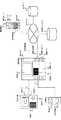
図1は、本発明の実施例によるテレビドアホンシステムの構成を示すシステム説明図であり、図2は、本発明の実施例によるテレビドアホンシステムにおいて、後述する玄関子機1、センサカメラ2および室内親機3の具体的な構成を示すブロック図である。   FIG. 1 is a system explanatory diagram showing a configuration of a television door phone system according to an embodiment of the present invention. FIG. 2 is a diagram illustrating a door door device 1, a sensor camera 2, and a room described later in the television door phone system according to an embodiment of the present invention. 3 is a block diagram showing a specific configuration of a parent device 3. FIG.

図1のシステム説明図に示すテレビドアホンシステムは、住戸外、例えば、住戸玄関に設置されており、来訪者が居住者を呼び出して通話を行うとともに、被写体である呼出操作を行った来訪者(住戸玄関の周囲環境を含む)の静止画像若しくは動画像を撮像し、さらに、居住者にとって好ましくない不審者を音で威嚇するための発報機能を備えた玄関子機1と、玄関子機1の設置場所とは異なる住戸玄関の周囲環境に設置されており、不審者が存在しているか否かを監視/感知し、監視画像として静止画像若しくは動画像を撮像するためのセンサカメラ2と、住戸内に設置されており、子機ラインL1を介して接続される玄関子機1からの呼び出し、すなわち、来訪者からの呼び出しを報知するとともに、玄関子機1若しくはカメララインL2を介して接続されるセンサカメラ2にて撮像された静止画像若しくは動画像を出画し、出画された静止画像若しくは動画像を視認しながら居住者が来訪者との間で通話を行い、さらに、玄関子機1から音で不審者を威嚇するための威嚇起動機能を備えた室内親機3と、外出等で住戸内を不在にしている居住者により携行され、玄関子機1からの呼び出し、すなわち、来訪者からの呼び出しが転送(転送報知)されるとともに、玄関子機1若しくはセンサカメラ2にて撮像された静止画像若しくは動画像を出画し、出画された静止画像若しくは動画像を視認しながら外出中の居住者が来訪者との間で通話を行い、さらに、玄関子機1から音で不審者を威嚇するための威嚇起動機能を備えたPHS(Personal Handyphone System)等の携帯端末4と、玄関子機1若しくはセンサカメラ2にて撮像された静止画像若しくは動画像を出画するとともに、不審者に対応する機能を備えた警備会社等の専用サービスセンター5と、携帯端末4との間で通信が可能であり、玄関子機1若しくはセンサカメラ2にて撮像された静止画像若しくは動画像をアップロードするための専用サーバ6と、室内親機3と後述するインターネット9との間を接続するためのPHS網等の無線通信網7またはADSL(Asymmetric Digital Subscriber Line)網等の有線通信網8と、専用サービスセンター5、専用サーバ6、無線通信網7または有線通信網8の各部をそれぞれ接続する通信網をなすインターネット9とから構成されており、インターネット9には、通常、サービスプロバイダ機能も含まれる。   The TV door phone system shown in the system explanatory diagram of FIG. 1 is installed outside a dwelling unit, for example, at a dwelling unit entrance, and a visitor who calls a resident and makes a call and performs a call operation as a subject ( The entrance cordless handset 1 having a notification function for capturing a still image or a moving image (including the surrounding environment of the dwelling entrance) and threatening a suspicious person unfavorable to the resident by sound, and the entrance cordless handset 1 A sensor camera 2 for monitoring / sensing whether a suspicious person is present and capturing a still image or a moving image as a monitoring image; Called from the entrance cordless handset 1 installed in the dwelling unit and connected via the cordless handset line L1, that is, a call from the visitor, and the entrance cordless handset 1 or the camera line L 2 A still image or a moving image captured by the sensor camera 2 connected via 2 is displayed, and a resident makes a call with a visitor while viewing the displayed still image or moving image. Furthermore, it is carried by the indoor master unit 3 having a threatening activation function for threatening the suspicious person with sound from the entrance cordless handset 1 and a resident who is out of the residence due to going out, etc. Call, that is, a call from a visitor is transferred (transfer notification), and a still image or a moving image captured by the front door unit 1 or the sensor camera 2 is displayed, and the displayed still image or A PHS (Personal Handyphone System) equipped with a threatening activation function for intimidating a suspicious person with sound from the entrance cordless handset 1 while a resident who is out of the office makes a call with a visitor while viewing a moving image Mobile terminal 4 and the entrance The mobile terminal 4 communicates with a dedicated service center 5 such as a security company that displays a still image or a moving image captured by the machine 1 or the sensor camera 2 and has a function for dealing with a suspicious person. PHS for connecting a dedicated server 6 for uploading a still image or a moving image captured by the front door unit 1 or the sensor camera 2 and the indoor base unit 3 and the Internet 9 described later. A communication network for connecting a wireless communication network 7 such as a network or a wired communication network 8 such as an ADSL (Asymmetric Digital Subscriber Line) network to each part of the dedicated service center 5, the dedicated server 6, the wireless communication network 7 or the wired communication network 8. The Internet 9 generally includes a service provider function.

図2のブロック図において、玄関子機1には、来訪者が呼び出しのために操作する呼出ボタン10と、来訪者による呼出ボタン10の操作を検出し、その旨の呼出信号を出力するための呼出回路11と、呼出ボタン10を操作した来訪者(住戸玄関の周囲環境を含む)の静止画像若しくは動画像を撮像するためのカメラ(以下、子機カメラという。)12と、子機カメラ12にて撮像された静止画像若しくは動画像の画像信号をFM変調するための画像変調回路(以下、子機カメラ画像変調回路という。)13と、来訪者が住戸内に在室中の居住者または外出中の居住者、或いは専用サービスセンター5内の人物との間で通話を行うための送話音声を入力するマイク(以下、子機マイクという。)14と、子機マイク14とともに来訪者が通話を行うために使用し、居住者または外出中の居住者、或いは専用サービスセンター5内の人物の受話音声が出力されるとともに、後述する室内親機3または携帯端末4からの威嚇起動操作により不審者を威嚇するための音、例えば、警報音(音声メッセージを含む)を発報するスピーカ(以下、子機スピーカという。)15と、子機マイク14から入力された送話音声の音声信号を増幅するための送話アンプ(以下、子機送話アンプという。)16と、子機スピーカ15から出力される受話音声の音声信号、警報音(音声メッセージを含む)の音データをそれぞれ増幅するための受話アンプ(以下、子機受話アンプという。)17と、子機送話アンプ16を介して増幅された音声信号を4線/2線変換するとともに、子機受話アンプ17に出力される音声信号、音データをそれぞれ2線/4線変換するためのハイブリット回路(以下、子機ハイブリット回路という。)18と、呼出回路11、子機カメラ画像変調回路13、子機ハイブリット回路18の各部および子機ラインL1の間の信号/データ伝送路をそれぞれ形成するための通信インターフェース(以下、子機I/Fという。)19とが備えられており、上述の呼出ボタン10、子機カメラ12、子機マイク14および子機スピーカ15は、それぞれ図1のシステム説明図の玄関子機1に示される。   In the block diagram of FIG. 2, the entrance cordless handset 1 detects a call button 10 that a visitor operates for calling, and an operation of the call button 10 by a visitor, and outputs a call signal to that effect. A call circuit 11, a camera (hereinafter referred to as a slave camera) 12 for capturing a still image or a moving image of a visitor (including the surrounding environment of the dwelling entrance) who operates the call button 10, and a slave camera 12 An image modulation circuit (hereinafter referred to as a slave camera image modulation circuit) 13 for FM-modulating an image signal of a still image or a moving image picked up by a resident, A visitor with a microphone (hereinafter referred to as a slave microphone) 14 for inputting a transmission voice for making a call with a resident who is out of the office or a person in the dedicated service center 5 and a slave microphone 14. Through The voice of the resident, the resident who is out of the office, or the person in the dedicated service center 5 is output, and suspicious by the threatening activation operation from the indoor base unit 3 or the portable terminal 4 to be described later Sound for intimidating a person, for example, a speaker (hereinafter referred to as a slave unit speaker) 15 that issues an alarm sound (including a voice message) and a voice signal of a transmission voice input from the slave unit microphone 14 Amplifying transmission data (hereinafter referred to as “slave device transmission amplifier”) 16 for amplifying, and a sound signal of a reception voice and an alarm sound (including a voice message) output from the handset speaker 15 are amplified. 4 is converted into a 4-line / 2-line audio signal via the receiver amplifier (hereinafter referred to as a slave receiver amplifier) 17 and the slave transmitter amplifier 16, and the slave receiver amplifier 17 A hybrid circuit (hereinafter referred to as a slave unit hybrid circuit) 18 for converting the input voice signal and sound data into two-line / four-line, respectively, a calling circuit 11, a slave camera image modulation circuit 13, and a slave hybrid circuit 18 and a communication interface (hereinafter referred to as a slave unit I / F) 19 for forming a signal / data transmission path between each unit and the slave unit line L1, respectively. The machine camera 12, the child machine microphone 14, and the child machine speaker 15 are respectively shown in the entrance child machine 1 in the system explanatory diagram of FIG.

また、図2のブロック図において、センサカメラ2には、不審者が住戸玄関の周囲環境に存在しているか否かを監視/感知するための人体感知センサ20と、人体感知センサ20にて不審者の存在が感知されたことを検出し、その旨の人体感知信号を出力するための人体感知回路21と、人体感知センサ20にて感知された不審者(住戸玄関の周囲環境を含む)の静止画像若しくは動画像を撮像するためのカメラ(以下、監視カメラという。)22と、監視カメラ22にて撮像された静止画像若しくは動画像の画像信号をFM変調するための画像変調回路(以下、監視カメラ画像変調回路という。)23と、人体感知回路21、監視カメラ画像変調回路23およびカメララインL2の間の信号伝送路をそれぞれ形成するための通信インターフェース(以下、カメラI/Fという。)24とが備えられており、上述の人体感知センサ20、監視カメラ22は、それぞれ図1のシステム説明図のセンサカメラ2に示される。   In the block diagram of FIG. 2, the sensor camera 2 includes a human body detection sensor 20 for monitoring / sensing whether or not a suspicious person is present in the surrounding environment of the dwelling unit entrance, and a suspicious person by the human body detection sensor 20. A human body sensing circuit 21 for detecting the presence of a person and outputting a human body sensing signal to that effect, and a suspicious person (including the surrounding environment of a dwelling entrance) sensed by the human body sensor 20 A camera (hereinafter referred to as a surveillance camera) 22 for capturing a still image or a moving image, and an image modulation circuit (hereinafter referred to as an image modulation circuit for FM-modulating an image signal of the still image or the moving image captured by the surveillance camera 22). And a communication interface for forming signal transmission paths among the human body sensing circuit 21, the surveillance camera image modulation circuit 23, and the camera line L2. 1 (hereinafter referred to as camera I / F) 24. The human body sensor 20 and the monitoring camera 22 described above are shown in the sensor camera 2 in the system explanatory diagram of FIG.

また、図2のブロック図において、室内親機3には、当該室内親機の構成各部をそれぞれ制御するために設けられ、後述する画像圧縮/伸張回路30a、音声圧縮/伸張回路30bを有する制御CPU30と、来訪者により玄関子機1の呼出ボタン10が操作されたことを検出し、その旨の呼出検出信号を制御CPU30に出力するための呼出検出回路31と、センサカメラ2の人体感知センサ20にて不審者の存在が感知されたことを検出し、その旨の人体感知検出信号を制御CPU30に出力するための人体感知検出回路32と、玄関子機1の子機カメラ12若しくはセンサカメラ2の監視カメラ22にて撮像された静止画像若しくは動画像であり、FM変調された画像信号を復調するための画像復調回路33と、画像復調回路33を介して復調された画像信号をもとに、玄関子機1の子機カメラ12若しくはセンサカメラ2の監視カメラ22にて撮像された静止画像若しくは動画像を出画するためのモニタ(以下、親機モニタという。)34と、来訪者により玄関子機1の呼出ボタン10が操作された旨の呼出音(音声メッセージを含む)、センサカメラ2の人体感知センサ20にて不審者の存在が感知された旨の警報音(音声メッセージを含む)をそれぞれ出力/発報するとともに、住戸内に在室中の居住者が通話を行うために使用し、来訪者の受話音声を出力するスピーカ(以下、親機スピーカという。)35と、親機スピーカ35とともに住戸内に在室中の居住者が通話を行うために使用し、送話音声を入力するマイク(以下、親機マイクという。)36と、親機スピーカ35から出力される受話音声の音声信号、親機スピーカ35から出力される制御CPU30からの呼出音(音声メッセージを含む)の音データ、警報音(音声メッセージを含む)の音データをそれぞれ増幅するための受話アンプ(以下、親機受話アンプという。)37と、親機マイク36から入力された送話音声の音声信号を増幅するための送話アンプ(以下、親機送話アンプという。)38と、親機スピーカ35から出力される送話音声が親機マイク36へ帰還することにより発生するハウリングを防止させるためのハンズフリー制御回路39と、ハンズフリー制御回路39に出力される音声信号の入力元を親機送話アンプ38または後述する音声コーデック回路43へ切り替えるとともに、ハンズフリー制御回路39から出力される音声信号の出力先を親機受話アンプ37または後述する音声コーデック回路43へ切り替えるための通話切替スイッチ40と、ハンズフリー制御回路39に出力される音声信号を2線/4線変換するとともに、ハンズフリー制御回路39を介した音声信号または制御CPU30からの(威嚇のための)警報音(音声メッセージを含む)の音データを4線/2線変換するためのハイブリット回路(以下、親機ハイブリット回路という。)41と、画像復調回路33を介して復調された画像信号をA/D変換(アナログ/デジタル変換)するとともに、後述するメモリ44から読み出され制御CPU30の画像圧縮/伸張回路30aを介して伸張された画像データをD/A変換(デジタル/アナログ変換)するための画像コーデック回路42と、通話切替スイッチ40を介した音声信号をA/D変換するとともに、後述するメモリ44から読み出され制御CPU30の音声圧縮/伸張回路30bを介して伸張された音声データをD/A変換するための音声コーデック回路43と、制御CPU30の画像圧縮/伸張回路30aを介して圧縮された画像データおよび音声圧縮/伸張回路30bを介して圧縮された音声データを保存するとともに、親機スピーカ35、玄関子機1の子機スピーカ15からそれぞれ出力/発報させるための音データ、携帯端末4に割り当てられている端末番号、専用サービスセンター5に割り当てられているセンター番号、専用サーバ6に割り当てられているサーバ番号、無線通信網7または有線通信網8を介してインターネット9との間で通信を行うための所定の通信プログラム(詳述せず)が予め保存されたメモリ44と、来訪者からの呼び出しに応答するために住戸内に在室中の居住者が操作する通話ボタン45と、玄関子機1の子機カメラ12若しくはセンサカメラ2の監視カメラ22にて撮像された静止画像若しくは動画像の画像データについて、無線通信網7または有線通信網8とインターネット9とを介して携帯端末4若しくは専用サービスセンター5に転送させるために住戸内に在室中の居住者が操作する通話転送ボタン46と、不審者に対して音で威嚇するために住戸内に在室中の居住者が操作する威嚇ボタン47と、呼出検出回路31、人体感知検出回路32、画像復調回路33、親機ハイブリット回路41の各部および子機ラインL1、カメララインL2の間の信号/データ伝送路をそれぞれ形成するための通信インターフェース(以下、子機・センサカメラ側親機I/Fという。)48と、制御CPU30および無線通信網7の間のデータ伝送路を形成するための無線通信インターフェース(以下、無線側親機I/Fという。)49と、制御CPU30および有線通信網8の間のデータ伝送路を形成するための有線通信インターフェース(以下、有線側親機I/Fという。)50とが備えられており、上述の親機モニタ34、親機スピーカ35、親機マイク36、通話ボタン45、通話転送ボタン46、威嚇ボタン47は、それぞれ図1のシステム説明図の室内親機3に示される。   In the block diagram of FIG. 2, the indoor master unit 3 is provided for controlling each component of the indoor master unit, and includes an image compression / decompression circuit 30a and an audio compression / decompression circuit 30b described later. CPU 30, a call detection circuit 31 for detecting that the call button 10 of the front door 1 is operated by a visitor, and outputting a call detection signal to that effect to the control CPU 30, and a human body sensor of the sensor camera 2 20 detects the presence of a suspicious person, and outputs a human body detection detection signal to that effect to the control CPU 30, and the child camera 12 or sensor camera of the entrance child machine 1. The image demodulating circuit 33 for demodulating an FM-modulated image signal, which is a still image or a moving image captured by the second monitoring camera 22, and the image demodulating circuit 33 Based on the image signal demodulated in this manner, a monitor (hereinafter referred to as a master unit) for outputting a still image or a moving image captured by the slave camera 12 of the entrance slave unit 1 or the monitoring camera 22 of the sensor camera 2. 34), a ringing sound (including a voice message) indicating that the call button 10 of the entrance cordless handset 1 has been operated by a visitor, and the presence of a suspicious person is detected by the human body sensor 20 of the sensor camera 2. A warning sound (including a voice message) is output / alarmed, and a speaker (hereinafter referred to as the following) is used to make a call by a resident in the residence and to make a call. 35) and a microphone (hereinafter referred to as a “base unit microphone”) 36 that is used by a resident who is present in the dwelling unit together with the master unit speaker 35 to make a telephone call and inputs a transmitted voice. , Master machine The voice signal of the received voice output from the power source 35, the sound data of the ringing sound (including voice message) and the sound data of the warning sound (including voice message) from the control CPU 30 output from the master speaker 35 are amplified. Receiver amplifier (hereinafter referred to as “base unit receiver amplifier”) 37 and a transmitter amplifier (hereinafter referred to as “base unit transmitter amplifier”) for amplifying the voice signal of the transmitted voice input from base unit microphone 36. ) 38, a hands-free control circuit 39 for preventing howling that occurs when the transmitted voice output from the parent speaker 35 returns to the parent microphone 36, and the voice output to the hands-free control circuit 39. The input source of the signal is switched to the base unit transmission amplifier 38 or the voice codec circuit 43 described later, and the sound output from the hands-free control circuit 39 The voice changeover switch 40 for switching the output destination of the voice signal to the master receiver amplifier 37 or the voice codec circuit 43 described later and the voice signal output to the hands-free control circuit 39 are converted into two-line / four-line, and the hands. A hybrid circuit (hereinafter referred to as a master unit hybrid circuit) for converting the audio signal via the free control circuit 39 or the sound data of the alarm sound (including the voice message) from the control CPU 30 (including the voice message) into four lines / 2 lines. That's it. 41) and A / D conversion (analog / digital conversion) of the image signal demodulated through the image demodulation circuit 33, and also read out from the memory 44 described later through the image compression / expansion circuit 30a of the control CPU 30. The image codec circuit 42 for D / A conversion (digital / analog conversion) of the decompressed image data and the audio signal via the call changeover switch 40 are A / D converted and read from a memory 44 described later. An audio codec circuit 43 for D / A converting audio data expanded via the audio compression / expansion circuit 30b of the control CPU 30, and image data and audio compressed via the image compression / expansion circuit 30a of the control CPU 30 The audio data compressed through the compression / decompression circuit 30b is stored, and the parent speaker 35 and the child of the entrance child device 1 are stored. Sound data to be output / reported from the speaker 15, terminal number assigned to the mobile terminal 4, center number assigned to the dedicated service center 5, server number assigned to the dedicated server 6, wireless communication A predetermined communication program (not described in detail) for communicating with the Internet 9 via the network 7 or the wired communication network 8 is stored in advance, and in order to respond to a call from a visitor Wireless communication is performed on the image data of still images or moving images captured by the call button 45 operated by a resident in the room and the slave camera 12 of the entrance slave unit 1 or the monitoring camera 22 of the sensor camera 2. A dwelling unit for transfer to the portable terminal 4 or the dedicated service center 5 via the communication network 7 or the wired communication network 8 and the Internet 9 A call transfer button 46 operated by a resident in the room, a threatening button 47 operated by a resident in the dwelling unit to intimidate the suspicious person with sound, a call detection circuit 31, and a human body. Communication interfaces (hereinafter referred to as slave units and sensor cameras) for forming signal / data transmission paths between the sensing detection circuit 32, the image demodulation circuit 33, the base unit hybrid circuit 41, and the slave unit line L1 and the camera line L2, respectively. 48), a wireless communication interface (hereinafter referred to as a wireless parent device I / F) 49 for forming a data transmission path between the control CPU 30 and the wireless communication network 7, and a control. And a wired communication interface (hereinafter referred to as a wired-side master unit I / F) 50 for forming a data transmission path between the CPU 30 and the wired communication network 8. Monitor 34, the master unit speaker 35, the master unit microphone 36, a call button 45, call forwarding button 46, intimidating button 47 is shown in the indoor base unit 3 of the system diagram of FIG. 1, respectively.

さらに、図1のシステム説明図において、携帯端末4は、来訪者により玄関子機1の呼出ボタン10が操作された旨の内容を出画するとともに、玄関子機1の子機カメラ12若しくはセンサカメラ2の監視カメラ22にて撮像された静止画像若しくは動画像を出画するためのモニタ(以下、端末モニタという。)60と、来訪者により玄関子機1の呼出ボタン10が操作された旨の呼出音(音声メッセージを含む)、センサカメラ2の人体感知センサ20にて不審者の存在が感知された旨の警報音(音声メッセージを含む)をそれぞれ出力/発報するとともに、外出中の居住者が通話を行うために使用し、来訪者の受話音声を出力するスピーカ(以下、端末スピーカという。)61と、端末スピーカ61とともに外出中の居住者が通話をを行うために使用し、送話音声を入力するマイク(以下、端末マイクという。)62と、来訪者からの呼び出しに応答するための操作や不審者に対して威嚇するための操作が外出中の居住者により行われるテンキーボタン等の操作部(以下、端末操作部という。)63とを有している。   Further, in the system explanatory diagram of FIG. 1, the mobile terminal 4 displays a content indicating that the call button 10 of the entrance cordless handset 1 has been operated by a visitor, and the handset camera 12 or sensor of the entrance cordless handset 1. A monitor (hereinafter referred to as a terminal monitor) 60 for displaying a still image or a moving image captured by the monitoring camera 22 of the camera 2 and a call button 10 of the entrance cordless handset 1 being operated by a visitor. And a warning sound (including a voice message) indicating that the presence of a suspicious person has been detected by the human body sensor 20 of the sensor camera 2 and a warning sound (including a voice message). A speaker (hereinafter referred to as a terminal speaker) 61 that is used by a resident to make a call and outputs a received voice of a visitor, and a resident who is out of the office with the terminal speaker 61 make a call. Used for the purpose, and a microphone (hereinafter referred to as a terminal microphone) 62 for inputting a transmitted voice, and an operation for responding to a call from a visitor or an operation for threatening a suspicious person. And an operation unit (hereinafter referred to as a terminal operation unit) 63 such as a numeric key button performed by a person.

このように構成された本発明の実施例によるテレビドアホンシステムにおいて、以下、具体的な動作について説明する。   In the TV door phone system according to the embodiment of the present invention configured as described above, a specific operation will be described below.

本発明の実施例における第1の動作として、住戸玄関に居る来訪者が図1のシステム説明図および図2のブロック図に示す玄関子機1の呼出ボタン10を操作すると、この呼出操作を検出した呼出回路11から子機I/F19、子機ラインL1、室内親機3の子機・センサカメラ側親機I/F48を介して呼出検出回路31へと呼出信号が伝送されるとともに、呼出操作を行った来訪者(住戸玄関の周囲環境を含む)の静止画像若しくは動画像が子機カメラ12にて撮像開始される。また、子機カメラ12にて撮像が開始された静止画像若しくは動画像は、子機カメラ画像変調回路13を介してFM変調された画像信号として、子機I/F19、子機ラインL1、室内親機3の子機・センサカメラ側親機I/F48を介して画像復調回路33へと伝送される。   As a first operation in the embodiment of the present invention, when a visitor at the entrance of the dwelling operates the call button 10 of the entrance cordless handset 1 shown in the system explanatory diagram of FIG. 1 and the block diagram of FIG. 2, this call operation is detected. The call signal is transmitted from the calling circuit 11 to the call detection circuit 31 via the child device I / F 19, the child device line L 1, and the child device / sensor camera side parent device I / F 48 of the indoor parent device 3. The slave camera 12 starts to capture a still image or a moving image of the visitor who performed the operation (including the surrounding environment of the dwelling entrance). In addition, the still image or the moving image whose imaging is started by the slave camera 12 is processed as an FM-modulated image signal via the slave camera image modulation circuit 13, and the slave I / F 19, the slave line L1, the room The data is transmitted to the image demodulation circuit 33 via the slave unit / sensor camera side master unit I / F 48 of the master unit 3.

室内親機3の呼出検出回路31は、玄関子機1からの呼出信号をもとに来訪者からの呼び出しがあることを検出し、その旨の呼出検出信号を制御CPU30に出力する。   The call detection circuit 31 of the indoor parent device 3 detects that there is a call from a visitor based on the call signal from the entrance child device 1, and outputs a call detection signal to that effect to the control CPU 30.

室内親機3の制御CPU30は、呼出検出回路31からの呼出検出信号を検出すると、呼出報知を行うための音データをメモリ44から読み出し、読み出された音データを親機受話アンプ37を介して増幅させるとともに、画像復調回路33、親機モニタ34がそれぞれ能動となるように制御することにより、来訪者からの呼び出しがある旨の呼出音(音声メッセージを含む)が親機スピーカ35から出力されるとともに、親機モニタ34には、画像復調回路33を介して復調された画像信号、すなわち、玄関子機1の子機カメラ12にて撮像された来訪者(住戸玄関の周囲環境を含む)の静止画像若しくは動画像が出画される。   When detecting the call detection signal from the call detection circuit 31, the control CPU 30 of the indoor base unit 3 reads out sound data for calling notification from the memory 44, and reads the read sound data via the base unit receiver amplifier 37. And the image demodulating circuit 33 and the parent device monitor 34 are controlled to be active, so that a ringing sound (including a voice message) indicating that there is a call from a visitor is output from the parent device speaker 35. At the same time, the master monitor 34 includes an image signal demodulated through the image demodulating circuit 33, that is, a visitor imaged by the slave camera 12 of the front door 1 (including the surrounding environment of the dwelling entrance). ) Still image or moving image.

上述のように、図1のシステム説明図および図2のブロック図に示す室内親機3の親機モニタ34に出画されている静止画像若しくは動画像と親機スピーカ35からの呼出音(音声メッセージを含む)の出力とをもとに、来訪者からの呼び出しを当該来訪者の識別と併せて確認した住戸内に在室中の居住者が通話ボタン45を操作すると、この応答操作を検出した制御CPU30によりハンズフリー制御回路39、親機ハイブリット回路41がそれぞれ能動となるように制御されるとともに、通話切替スイッチ40が制御され、住戸内に在室中の居住者が使用する親機スピーカ35および親機マイク36と親機受話アンプ37および親機送話アンプ38、通話切替スイッチ40、ハンズフリー制御回路39、親機ハイブリット回路41、子機・センサカメラ側親機I/F48、子機ラインL1、玄関子機1の子機I/F19、子機ハイブリット回路18、子機送話アンプ16および子機受話アンプ17を介して来訪者が使用する子機マイク14および子機スピーカ15との間の通話路が形成され、形成された通話路を介して音声信号を送受信させることにより通話を行うことができ、住戸内に在室中の居住者にとっては、室内親機3の親機モニタ34に出画されている来訪者の静止画像若しくは動画像を視認しながら通話を行うことができる。   As described above, the still image or the moving image displayed on the parent device monitor 34 of the indoor parent device 3 shown in the system explanatory diagram of FIG. 1 and the block diagram of FIG. The response operation is detected when a resident in the room operates the call button 45 in the dwelling unit that has confirmed the call from the visitor together with the identification of the visitor based on the output of the message (including the message). The control CPU 30 controls the hands-free control circuit 39 and the base unit hybrid circuit 41 to be active, and the call switch 40 is controlled to control the base unit speaker used by a resident in the room. 35, a master microphone 36, a master receiver amplifier 37, a master transmitter amplifier 38, a call switch 40, a hands-free control circuit 39, a master hybrid circuit 41, and a slave. Used by visitors via the sensor camera side main unit I / F 48, the sub unit line L1, the sub unit I / F 19 of the entrance sub unit 1, the sub unit hybrid circuit 18, the sub unit transmission amplifier 16 and the sub unit reception amplifier 17. A communication path between the handset microphone 14 and the handset speaker 15 is formed, and a call can be performed by transmitting and receiving audio signals through the formed call path. A person can make a call while visually recognizing a still image or a moving image of a visitor displayed on the parent device monitor 34 of the indoor parent device 3.

次に、本発明の実施例における第2の動作として、上述の第1の動作から明らかなように、図1のシステム説明図および図2のブロック図に示す玄関子機1の子機マイク14および子機スピーカ15と室内親機3の親機スピーカ35および親機マイク36との間の通話路が形成されている際、すなわち、来訪者と住戸内に在室中の居住者との間で通話が行われている状態において、通話中の来訪者(住戸玄関の周囲環境を含む)に対して不信感を持った住戸内に在室中の居住者が威嚇ボタン47を操作すると、この威嚇起動操作を検出した制御CPU30により通話切替スイッチ40が制御され、上述のような親機スピーカ35および親機マイク36と玄関子機1の子機マイク14および子機スピーカ15との間の通話路が切断されるとともに、威嚇報知のための音データがメモリ44から読み出される。この音データは、制御CPU30により能動に制御されている親機ハイブリット回路41、子機・センサカメラ側親機I/F48、子機ラインL1、玄関子機1の子機I/F19、子機ハイブリット回路18、子機受話アンプ17を介して子機スピーカ15へと伝送されることにより、警報音(音声メッセージを含む)が子機スピーカ15から発報され、住戸内に在室中の居住者に不信感を与えた通話中の来訪者(住戸玄関の周囲環境を含む)に対して威嚇することができ防犯性が高められる。   Next, as the second operation in the embodiment of the present invention, as is apparent from the first operation described above, the handset microphone 14 of the entrance handset 1 shown in the system explanatory diagram of FIG. 1 and the block diagram of FIG. When a communication path is formed between the handset speaker 15 and the base unit speaker 35 and the base unit microphone 36 of the indoor base unit 3, that is, between a visitor and a resident in the residence. If a resident in the room operates intimidating button 47 in a dwelling unit that is distrustful to visitors during the call (including the surrounding environment of the dwelling entrance), The call switching switch 40 is controlled by the control CPU 30 that has detected the threatening activation operation, and the call between the parent speaker 35 and the parent microphone 36 and the child microphone 14 and the child speaker 15 of the entrance child device 1 as described above. When the road is cut off , Sound data for threat notification is read from the memory 44. This sound data is obtained from the parent device hybrid circuit 41 actively controlled by the control CPU 30, the child device / sensor camera side parent device I / F 48, the child device line L1, the child device I / F 19 of the front door child device 1, the child device. The alarm sound (including a voice message) is issued from the handset speaker 15 by being transmitted to the handset speaker 15 via the hybrid circuit 18 and the handset receiver amplifier 17, and the occupants in the room in the dwelling unit. It is possible to intimidate visitors (including the surrounding environment of the entrance to the dwelling unit) during a call that gives distrust to the person, and crime prevention is improved.

次に、本発明の実施例における第3の動作として、(居住者にとって好ましくない)不審者が住戸玄関の周囲環境に居り、この不審者の存在を図1のシステム説明図および図2のブロック図に示すセンサカメラ2の人体感知センサ20が感知すると、これを検出した人体感知回路21からカメラI/F24、カメララインL2、室内親機3の子機・センサカメラ側親機I/F48を介して人体感知検出回路32へと人体感知信号が伝送されるとともに、不審者(住戸玄関の周囲環境を含む)の静止画像若しくは動画像が監視カメラ22にて撮像開始される。また、監視カメラ22にて撮像が開始された静止画像若しくは動画像は、監視カメラ画像変調回路23を介してFM変調された画像信号として、カメラI/F24、カメララインL2、室内親機3の子機・センサカメラ側親機I/F48を介して画像復調回路33へと伝送される。   Next, as a third operation in the embodiment of the present invention, there is a suspicious person (not desirable for the resident) in the surrounding environment of the dwelling entrance, and the presence of this suspicious person is illustrated in the system explanatory diagram of FIG. 1 and the block of FIG. When the human body sensor 20 of the sensor camera 2 shown in the figure senses, the camera I / F 24, the camera line L 2, the slave unit / sensor camera side master unit I / F 48 of the indoor base unit 3 are detected from the human body detection circuit 21 that detects this. A human body sensing signal is transmitted to the human body sensing circuit 32 and a still image or a moving image of a suspicious person (including the surrounding environment of the dwelling entrance) is started to be captured by the monitoring camera 22. In addition, the still image or the moving image whose imaging has been started by the monitoring camera 22 is converted into an image signal that has been FM-modulated via the monitoring camera image modulation circuit 23, and the camera I / F 24, the camera line L 2, and the indoor base unit 3. The data is transmitted to the image demodulation circuit 33 via the slave unit / sensor camera side master unit I / F 48.

室内親機3の人体感知検出回路32は、センサカメラ2からの人体感知信号をもとに不審者の存在があることを検出し、その旨の人体感知検出信号を制御CPU30に出力する。   The human body detection detection circuit 32 of the indoor base unit 3 detects the presence of a suspicious person based on the human body detection signal from the sensor camera 2 and outputs a human body detection detection signal to that effect to the control CPU 30.

室内親機3の制御CPU30は、人体感知検出回路32からの人体感知検出信号を検出すると、警報報知のための音データをメモリ44から読み出し、読み出された音データを親機受話アンプ37を介して増幅させるとともに、画像復調回路33、親機モニタ34がそれぞれ能動となるように制御することにより、不審者の存在がある旨の警報音(音声メッセージを含む)が親機スピーカ35から発報されるとともに、親機モニタ34には、画像復調回路33を介して復調された画像信号、すなわち、センサカメラ2の監視カメラ22にて撮像された不審者(住戸玄関の周囲環境を含む)の静止画像若しくは動画像が出画される。   When the control CPU 30 of the indoor base unit 3 detects the human body detection detection signal from the human body detection detection circuit 32, it reads out sound data for alarm notification from the memory 44, and sends the read sound data to the base unit receiver amplifier 37. And the image demodulating circuit 33 and the master monitor 34 are controlled to be active, so that a warning sound (including a voice message) indicating the presence of a suspicious person is emitted from the master speaker 35. At the same time, the base unit monitor 34 receives the image signal demodulated through the image demodulating circuit 33, that is, the suspicious person imaged by the monitoring camera 22 of the sensor camera 2 (including the surrounding environment of the entrance to the dwelling unit). A still image or a moving image is output.

上述のように、図1のシステム説明図および図2のブロック図に示す室内親機3の親機モニタ34に出画されている静止画像若しくは動画像と親機スピーカ35からの警報音(音声メッセージを含む)の発報とをもとに、不審者の存在を当該不審者の識別と併せて確認した住戸内に在室中の居住者が威嚇ボタン47を操作すると、この威嚇起動操作を検出した制御CPU30の制御により威嚇報知のための音データがメモリ44から読み出される。この音データは、制御CPU30により能動に制御されている親機ハイブリット回路41、子機・センサカメラ側親機I/F48、子機ラインL1、玄関子機1の子機I/F19、子機ハイブリット回路18、子機受話アンプ17を介して子機スピーカ15へと伝送されることにより、警報音(音声メッセージを含む)が子機スピーカ15から発報され、住戸内に在室中の居住者に不信感を与えた不審者(住戸玄関の周囲環境を含む)に対して威嚇することができ防犯性が高められる。   As described above, a still image or a moving image displayed on the parent device monitor 34 of the indoor parent device 3 shown in the system explanatory diagram of FIG. 1 and the block diagram of FIG. If a resident in the room operates a threatening button 47 in a dwelling unit that has confirmed the presence of the suspicious person together with the identification of the suspicious person based on the Sound data for threatening notification is read from the memory 44 under the control of the detected control CPU 30. This sound data is obtained from the parent device hybrid circuit 41 actively controlled by the control CPU 30, the child device / sensor camera side parent device I / F 48, the child device line L1, the child device I / F 19 of the front door child device 1, the child device. The alarm sound (including a voice message) is issued from the handset speaker 15 by being transmitted to the handset speaker 15 via the hybrid circuit 18 and the handset receiver amplifier 17, and the occupants in the room in the dwelling unit. It can be intimidated against a suspicious person (including the surrounding environment of a dwelling unit entrance) that gives distrust to the person, and crime prevention is improved.

なお、本発明の実施例における第3の動作である住戸内に在室中の居住者に不信感を与えた不審者(住戸玄関の周囲環境を含む)に対して威嚇する動作は、上述の第1の動作時、すなわち、来訪者と住戸内に在室中の居住者との間で通話が行われている際においても行うことができる。   In addition, the operation intimidating the suspicious person (including the surrounding environment of the entrance to the dwelling unit) who gave distrust to the resident in the room, which is the third operation in the embodiment of the present invention, is described above. This can also be done during the first operation, that is, when a call is being made between a visitor and a resident in the room.

次に、本発明の実施例における第4の動作として、上述の第1の動作から明らかなように、図1のシステム説明図および図2のブロック図に示す室内親機3の親機モニタ34に出画されている静止画像若しくは動画像と親機スピーカ35からの呼出音(音声メッセージを含む)の出力とをもとに、来訪者からの呼び出しを当該来訪者の識別と併せて確認した住戸内に在室中の居住者が通話ボタン45を操作する前に通話転送ボタン46を操作すると、この手動録画操作を検出した制御CPU30により画像復調回路33、親機モニタ34への制御に加えて画像コーデック回路42が能動となるように制御される。   Next, as the fourth operation in the embodiment of the present invention, as apparent from the first operation described above, the parent device monitor 34 of the indoor parent device 3 shown in the system explanatory diagram of FIG. 1 and the block diagram of FIG. The call from the visitor was confirmed together with the identification of the visitor based on the still image or moving image displayed on the screen and the output of the ring tone (including voice message) from the main unit speaker 35. If a resident in the room operates the call transfer button 46 before operating the call button 45, the control CPU 30 that has detected the manual recording operation will control the image demodulation circuit 33 and the master monitor 34 in addition to the control. Thus, the image codec circuit 42 is controlled to be active.

室内親機3の画像コーデック回路42は、画像復調回路33を介して復調された画像信号、すなわち、親機モニタ34に出画されている来訪者(住戸玄関の周囲環境を含む)の静止画像若しくは動画像の画像信号をA/D変換して制御CPU30に出力する。   The image codec circuit 42 of the indoor parent device 3 is an image signal demodulated through the image demodulation circuit 33, that is, a still image of a visitor (including the surrounding environment of the dwelling entrance) displayed on the parent device monitor 34. Alternatively, the image signal of the moving image is A / D converted and output to the control CPU 30.

室内親機3の制御CPU30は、画像コーデック回路42からのデジタル画像データを画像圧縮/伸張回路30aを介して圧縮させ、圧縮されたデジタル画像データを転送する転送先として、携帯端末4若しくは専用サービスセンター5を指定するため、専用サーバ6に割り当てられているサーバ番号若しくは専用サービスセンター5に割り当てられているセンター番号と圧縮デジタル画像データをアップロードさせるための所定の通信プログラム(詳述せず)とをメモリ44から読み出し、読み出されたサーバ番号若しくはセンター番号、所定の通信プログラム(詳述せず)と圧縮デジタル画像データとを付加させた画像転送データ(以下、第1の来訪者画像転送データという。)を生成する。この第1の来訪者画像転送データは、制御CPU30から無線側親機I/F49または有線側親機I/F50、無線通信網7または有線通信網8、インターネット9を介して専用サーバ6若しくは専用サービスセンター5へと伝送される。   The control CPU 30 of the indoor base unit 3 compresses the digital image data from the image codec circuit 42 via the image compression / decompression circuit 30a, and uses the portable terminal 4 or a dedicated service as a transfer destination for transferring the compressed digital image data. In order to designate the center 5, a server number assigned to the dedicated server 6 or a center number assigned to the dedicated service center 5 and a predetermined communication program (not detailed) for uploading the compressed digital image data Is read from the memory 44, and the read server number or center number, a predetermined communication program (not described in detail) and compressed digital image data are added to the image transfer data (hereinafter referred to as first visitor image transfer data). Is generated). This first visitor image transfer data is sent from the control CPU 30 via the wireless server I / F 49 or the wired host device I / F 50, the wireless communication network 7 or the wired communication network 8, and the dedicated server 6 or dedicated via the Internet 9. It is transmitted to the service center 5.

なお、室内親機3の制御CPU30は、画像圧縮/伸張回路30aを介して圧縮されたデジタル画像データ、すなわち、来訪者(住戸玄関の周囲環境を含む)の静止画像若しくは動画像の圧縮デジタル画像データをメモリ44に保存させることもできる。   The control CPU 30 of the indoor base unit 3 compresses digital image data compressed through the image compression / decompression circuit 30a, that is, a compressed digital image of a still image or a moving image of a visitor (including the surrounding environment of the entrance to the dwelling unit). Data can also be stored in the memory 44.

専用サーバ6は、室内親機3の制御CPU30からの第1の来訪者画像転送データに付加されている圧縮デジタル画像データを所定の通信プログラム(詳述せず)をもとにアップロードするとともに、アップロードされた旨の報知データ、例えば、メール(E-mail)を携帯端末4へと送信する。   The dedicated server 6 uploads the compressed digital image data added to the first visitor image transfer data from the control CPU 30 of the indoor parent device 3 based on a predetermined communication program (not detailed), The notification data indicating that the upload has been made, for example, e-mail is transmitted to the mobile terminal 4.

携帯端末4は、専用サーバ6からの報知データであるメールを受信し、圧縮デジタル画像データが専用サーバ6にアップロードされている旨の内容を文字や絵データで端末モニタ60に出画させるとともに、同様な内容を示す報知音(音声メッセージを含む)を端末スピーカ61から出力させることにより、これらを確認した外出中の居住者は、専用サーバ6へとアクセスして来訪者(住戸玄関の周囲環境を含む)の静止画像若しくは動画像のダウンロードおよび閲覧が可能となる。   The mobile terminal 4 receives the mail which is the notification data from the dedicated server 6 and causes the terminal monitor 60 to display the content that the compressed digital image data is uploaded to the dedicated server 6 on the terminal monitor 60, By outputting a notification sound (including a voice message) indicating the same content from the terminal speaker 61, a resident who has been confirmed to have accessed these accesses the dedicated server 6 and visits the surrounding environment of the dwelling unit entrance. And still images or moving images can be downloaded and viewed.

また、専用サービスセンター5は、室内親機3の制御CPU30からの第1の来訪者画像転送データに付加されている圧縮デジタル画像データを所定の通信プログラム(詳述せず)をもとにアップロードするとともに、来訪者(住戸玄関の周囲環境を含む)の静止画像若しくは動画像を出画させて当該専用サービスセンター内の人物、例えば、警備会社内の警備員に対して閲覧可能とすることにより、出画された来訪者(住戸玄関の周囲環境を含む)の静止画像若しくは動画像に警備員が不信感を持った場合には迅速に対応できる。   The dedicated service center 5 uploads the compressed digital image data added to the first visitor image transfer data from the control CPU 30 of the indoor base unit 3 based on a predetermined communication program (not detailed). In addition, by displaying a still image or a moving image of a visitor (including the surrounding environment of a dwelling unit entrance), it can be viewed by a person in the dedicated service center, for example, a security guard in a security company. When the security guard is distrusted by the still image or the moving image of the displayed visitor (including the surrounding environment of the dwelling unit entrance), it can respond quickly.

上述のように、図1のシステム説明図に示す携帯端末4の端末モニタ60に出画されている文字や絵データおよび来訪者(住戸玄関の周囲環境を含む)の静止画像若しくは動画像と端末スピーカ61からの報知音(音声メッセージを含む)の出力とをもとに、来訪者からの呼び出しを当該来訪者の識別と併せて確認した外出中の居住者が端末操作部63を使用して応答のための操作、例えば、所定のボタン操作(詳述せず)を行うと、上述の第1の来訪者画像転送データが伝送された経路と逆の経路を介して図2のブロック図に示す室内親機3の制御CPU30へと応答データが伝送される。   As described above, the characters and picture data displayed on the terminal monitor 60 of the mobile terminal 4 shown in the system explanatory diagram of FIG. 1 and the still image or moving image of the visitor (including the surrounding environment of the dwelling entrance) and the terminal Based on the notification sound (including voice message) output from the speaker 61, a resident who has gone out and confirmed the call from the visitor together with the identification of the visitor uses the terminal operation unit 63. When an operation for response, for example, a predetermined button operation (not described in detail) is performed, the block diagram of FIG. 2 passes through a path opposite to the path through which the first visitor image transfer data is transmitted. Response data is transmitted to the control CPU 30 of the indoor base unit 3 shown.

室内親機3の制御CPU30は、携帯端末4からの応答データを検出すると、ハンズフリー制御回路39、親機ハイブリット回路41への制御に加えて音声コーデック回路43が能動となるように制御するとともに、親機モニタ34への制御を停止し、さらに、通話切替スイッチ40を制御して、外出中の居住者が使用する携帯端末4の端末スピーカ61および端末マイク62とインターネット9、無線通信網7または有線通信網8、無線側親機I/F49または有線側親機I/F50、制御CPU30の音声圧縮/伸張回路30b、音声コーデック回路43、通話切替スイッチ40、ハンズフリー制御回路39、親機ハイブリット回路41、子機・センサカメラ側親機I/F48、子機ラインL1、玄関子機1の子機I/F19、子機ハイブリット回路18、子機送話アンプ16および子機受話アンプ17を介して来訪者が使用する子機マイク14および子機スピーカ15との間の通話路を形成させ、形成された通話路を介して音声信号を送受信させることにより通話を行うことができ、外出中の居住者にとっては、携帯端末4の端末モニタ60に出画されている来訪者の静止画像若しくは動画像を視認しながら通話を行うことができる。   When the control CPU 30 of the indoor base unit 3 detects response data from the portable terminal 4, in addition to controlling the hands-free control circuit 39 and the base unit hybrid circuit 41, the control CPU 30 controls the voice codec circuit 43 to be active. Then, the control to the master monitor 34 is stopped, and the call changeover switch 40 is further controlled so that the terminal speaker 61 and the terminal microphone 62 of the portable terminal 4 used by the resident who is out, the Internet 9, and the wireless communication network 7 Alternatively, the wired communication network 8, the wireless-side base unit I / F 49 or the wired-side base unit I / F 50, the voice compression / decompression circuit 30b of the control CPU 30, the voice codec circuit 43, the call changeover switch 40, the hands-free control circuit 39, the base unit Hybrid circuit 41, slave unit / sensor camera side master unit I / F 48, slave unit line L1, slave unit I / F 19 of the entrance slave unit 1, slave unit hive A communication path between the handset microphone 14 and the handset speaker 15 used by the visitor is formed via the lit circuit 18, the handset transmission amplifier 16 and the handset reception amplifier 17, and the communication path is formed via the formed communication path. The user can make a call by transmitting and receiving voice signals, and for a resident who is out, the call can be made while viewing the still image or moving image of the visitor displayed on the terminal monitor 60 of the portable terminal 4. It can be carried out.

なお、室内親機3の制御CPU30は、音声圧縮/伸張回路30bを介して圧縮されたデジタル音声データ(圧縮デジタル音声データ)をメモリ44に保存させることもできる(詳述せず)。   The control CPU 30 of the indoor parent device 3 can also store the digital audio data (compressed digital audio data) compressed through the audio compression / decompression circuit 30b in the memory 44 (not described in detail).

また、玄関子機1との間で通話を行う携帯端末4としてテレビ電話機能が備えられている場合には、テレビ電話による通話が可能となる。   In addition, when the mobile terminal 4 that makes a call with the entrance cordless handset 1 has a videophone function, a videophone call is possible.

次に、本発明の実施例における第5の動作として、上述の第3の動作から明らかなように、図1のシステム説明図および図2のブロック図に示す室内親機3の親機モニタ34に出画されている静止画像若しくは動画像と親機スピーカ35からの警報音(音声メッセージを含む)の発報とをもとに、不審者の存在を当該不審者の識別と併せて確認した住戸内に在室中の居住者が通話転送ボタン46を操作すると、この手動録画操作を検出した制御CPU30により画像復調回路33、親機モニタ34への制御に加えて画像コーデック回路42が能動となるように制御される。   Next, as the fifth operation in the embodiment of the present invention, as is apparent from the above-described third operation, the parent device monitor 34 of the indoor parent device 3 shown in the system explanatory diagram of FIG. 1 and the block diagram of FIG. The presence of the suspicious person was confirmed together with the identification of the suspicious person based on the still image or moving image displayed on the screen and the alarm sound (including voice message) from the parent speaker 35. When a resident in the room operates the call transfer button 46, the control CPU 30 that detects this manual recording operation activates the image codec circuit 42 in addition to controlling the image demodulation circuit 33 and the master monitor 34. It is controlled to become.

室内親機3の画像コーデック回路42は、画像復調回路33を介して復調された画像信号、すなわち、親機モニタ34に出画されている不審者(住戸玄関の周囲環境を含む)の静止画像若しくは動画像の画像信号をA/D変換して制御CPU30に出力する。   The image codec circuit 42 of the indoor base unit 3 is an image signal demodulated through the image demodulation circuit 33, that is, a still image of a suspicious person (including the surrounding environment of the dwelling entrance) displayed on the base unit monitor 34. Alternatively, the image signal of the moving image is A / D converted and output to the control CPU 30.

室内親機3の制御CPU30は、画像コーデック回路42からのデジタル画像データを画像圧縮/伸張回路30aを介して圧縮させ、圧縮されたデジタル画像データを転送する転送先として、携帯端末4若しくは専用サービスセンター5を指定するため、専用サーバ6に割り当てられているサーバ番号若しくは専用サービスセンター5に割り当てられているセンター番号と圧縮デジタル画像データをアップロードさせるための所定の通信プログラム(詳述せず)とをメモリ44から読み出し、読み出されたサーバ番号若しくはセンター番号、所定の通信プログラム(詳述せず)と圧縮デジタル画像データとを付加させた画像転送データ(以下、第1の不審者画像転送データという。)を生成する。この第1の不審者画像転送データは、上述の第1の来訪者画像転送データと同一の経路を介して専用サーバ6若しくは専用サービスセンター5へと伝送される。   The control CPU 30 of the indoor base unit 3 compresses the digital image data from the image codec circuit 42 via the image compression / decompression circuit 30a, and uses the portable terminal 4 or a dedicated service as a transfer destination for transferring the compressed digital image data. In order to designate the center 5, a server number assigned to the dedicated server 6 or a center number assigned to the dedicated service center 5 and a predetermined communication program (not detailed) for uploading the compressed digital image data Is transferred from the memory 44, and the read server number or center number, a predetermined communication program (not described in detail) and compressed digital image data are added to the image transfer data (hereinafter referred to as first suspicious person image transfer data). Is generated). The first suspicious person image transfer data is transmitted to the dedicated server 6 or the dedicated service center 5 through the same route as the first visitor image transfer data.

なお、室内親機3の制御CPU30は、画像圧縮/伸張回路30aを介して圧縮されたデジタル画像データ、すなわち、不審者(住戸玄関の周囲環境を含む)の静止画像若しくは動画像の圧縮デジタル画像データをメモリ44に保存させることもできる。   The control CPU 30 of the indoor base unit 3 compresses the digital image data compressed through the image compression / decompression circuit 30a, that is, a compressed digital image of a suspicious person (including the surrounding environment of the dwelling unit entrance) or a moving image. Data can also be stored in the memory 44.

専用サーバ6は、室内親機3の制御CPU30からの第1の不審者画像転送データに付加されている圧縮デジタル画像データを所定の通信プログラム(詳述せず)をもとにアップロードするとともに、アップロードされた旨の報知データ、例えば、メール(E-mail)を携帯端末4へと送信する。   The dedicated server 6 uploads the compressed digital image data added to the first suspicious person image transfer data from the control CPU 30 of the indoor base unit 3 based on a predetermined communication program (not detailed), The notification data indicating that the upload has been made, for example, e-mail is transmitted to the mobile terminal 4.

携帯端末4は、専用サーバ6からの報知データであるメールを受信し、圧縮デジタル画像データが専用サーバ6にアップロードされている旨の内容を文字や絵データで端末モニタ60に出画させるとともに、同様な内容を示す警報音(音声メッセージを含む)を端末スピーカ61から出力させることにより、これらを確認した外出中の居住者は、専用サーバ6へとアクセスして不審者(住戸玄関の周囲環境を含む)の静止画像若しくは動画像のダウンロードおよび閲覧が可能となる。   The mobile terminal 4 receives the mail which is the notification data from the dedicated server 6 and causes the terminal monitor 60 to display the content that the compressed digital image data is uploaded to the dedicated server 6 on the terminal monitor 60, By outputting an alarm sound (including a voice message) indicating the same content from the terminal speaker 61, a resident who has been confirmed to have accessed these accesses the dedicated server 6 and is a suspicious person (the surrounding environment of the dwelling entrance). And still images or moving images can be downloaded and viewed.

また、専用サービスセンター5は、室内親機3の制御CPU30からの第1の不審者画像転送データに付加されている圧縮デジタル画像データを所定の通信プログラム(詳述せず)をもとにアップロードするとともに、不審者(住戸玄関の周囲環境を含む)の静止画像若しくは動画像を出画させて当該専用サービスセンター内の人物、例えば、警備会社内の警備員に対して閲覧可能とすることにより、これを確認した警備員は迅速に対応できる。   The dedicated service center 5 uploads the compressed digital image data added to the first suspicious person image transfer data from the control CPU 30 of the indoor base unit 3 based on a predetermined communication program (not detailed). In addition, by displaying a still image or a moving image of a suspicious person (including the surrounding environment of a dwelling unit entrance), it can be viewed by a person in the dedicated service center, for example, a security guard in a security company. The security guard who confirmed this can respond quickly.

上述のように、図1のシステム説明図に示す携帯端末4の端末モニタ60に出画されている文字や絵データおよび不審者(住戸玄関の周囲環境を含む)の静止画像若しくは動画像と端末スピーカ61からの警報音(音声メッセージを含む)の発報とをもとに、不審者の存在を当該不審者の識別と併せて確認した外出中の居住者が端末操作部63を使用して威嚇のための操作、例えば、所定のボタン操作(詳述せず)を行うと、上述の応答データと同一の経路を介して図2のブロック図に示す室内親機3の制御CPU30へと威嚇起動データが伝送される。   As described above, the characters and picture data displayed on the terminal monitor 60 of the portable terminal 4 shown in the system explanatory diagram of FIG. 1 and the still image or moving image of the suspicious person (including the surrounding environment of the dwelling entrance) and the terminal Based on the alarm sound (including a voice message) from the speaker 61, a resident who has gone out and confirmed the presence of the suspicious person together with the identification of the suspicious person uses the terminal operation unit 63. When an operation for intimidation, for example, a predetermined button operation (not described in detail) is performed, the control CPU 30 of the indoor parent device 3 shown in the block diagram of FIG. 2 is intimidated through the same route as the response data described above. Startup data is transmitted.

室内親機3の制御CPU30は、携帯端末4からの威嚇起動データを検出すると、威嚇報知のための音データをメモリ44から読み出す。この音データは、制御CPU30により能動に制御されている親機ハイブリット回路41、子機・センサカメラ側親機I/F48、子機ラインL1、玄関子機1の子機I/F19、子機ハイブリット回路18、子機受話アンプ17を介して子機スピーカ15へと伝送されることにより、警報音(音声メッセージを含む)が子機スピーカ15から発報され、外出中の居住者に不信感を与えた不審者(住戸玄関の周囲環境を含む)に対して威嚇することができ防犯性が高められる。   When the control CPU 30 of the indoor parent device 3 detects threatening activation data from the portable terminal 4, it reads out sound data for threatening notification from the memory 44. This sound data is obtained from the parent device hybrid circuit 41 actively controlled by the control CPU 30, the child device / sensor camera side parent device I / F 48, the child device line L1, the child device I / F 19 of the front door child device 1, the child device. A warning sound (including a voice message) is issued from the handset speaker 15 by being transmitted to the handset speaker 15 via the hybrid circuit 18 and the handset receiver amplifier 17, and distrust to the resident who is out. Can be intimidated against suspicious persons (including the surrounding environment of the dwelling entrance) and crime prevention is improved.

次に、本発明の実施例における第6の動作として、上述の第4の動作から明らかなように、図1のシステム説明図および図2のブロック図に示す玄関子機1の子機マイク14および子機スピーカ15と携帯端末4の端末スピーカ61および端末マイク62との間の通話路が形成されている際、すなわち、来訪者と外出中の居住者との間で通話(テレビ電話による通話を含む)が行われている状態において、外出中の居住者が端末操作部63を使用して画像転送のための操作、例えば、所定のボタン操作(詳述せず)を行うと、上述の応答データ、威嚇起動データと同一の経路を介して室内親機3の制御CPU30へと画像転送起動データ(以下、来訪者画像転送起動データという。)が伝送される。   Next, as the sixth operation in the embodiment of the present invention, as is apparent from the above-described fourth operation, the handset microphone 14 of the entrance handset 1 shown in the system explanatory diagram of FIG. 1 and the block diagram of FIG. When the communication path between the handset speaker 15 and the terminal speaker 61 and the terminal microphone 62 of the mobile terminal 4 is formed, that is, between the visitor and the resident who is out (call by videophone) When the resident who is out of the office performs an operation for image transfer, for example, a predetermined button operation (not described in detail) using the terminal operation unit 63, the above-described operation is performed. Image transfer activation data (hereinafter referred to as visitor image transfer activation data) is transmitted to the control CPU 30 of the indoor parent device 3 through the same route as the response data and threatening activation data.

室内親機3の制御CPU30は、携帯端末4からの来訪者画像転送起動データを検出すると、画像コーデック回路42からのデジタル画像データ、すなわち、来訪者(住戸玄関の周囲環境を含む)の静止画像若しくは動画像のデジタル画像データを画像圧縮/伸張回路30aを介して圧縮させ、圧縮されたデジタル画像データを転送する転送先として、専用サービスセンター5を指定するため、専用サービスセンター5に割り当てられているセンター番号と圧縮デジタル画像データをアップロードさせるための所定の通信プログラム(詳述せず)とをメモリ44から読み出し、読み出されたセンター番号、所定の通信プログラム(詳述せず)と圧縮デジタル画像データとを付加させた画像転送データ(以下、第2の来訪者画像転送データという。)を生成する。この第2の来訪者画像転送データは、制御CPU30から無線側親機I/F49または有線側親機I/F50、無線通信網7または有線通信網8、インターネット9を介して専用サービスセンター5へと伝送される。   When the control CPU 30 of the indoor base unit 3 detects the visitor image transfer activation data from the portable terminal 4, the digital image data from the image codec circuit 42, that is, the still image of the visitor (including the surrounding environment of the dwelling entrance). Alternatively, it is assigned to the dedicated service center 5 in order to designate the dedicated service center 5 as a transfer destination for compressing the digital image data of the moving image via the image compression / decompression circuit 30a and transferring the compressed digital image data. The center number and a predetermined communication program (not detailed) for uploading compressed digital image data are read from the memory 44, and the read center number, the predetermined communication program (not detailed) and the compressed digital are read. Image transfer data to which image data is added (hereinafter referred to as second visitor image transfer data) .) To generate. The second visitor image transfer data is sent from the control CPU 30 to the dedicated service center 5 via the wireless side parent device I / F 49 or the wired side parent device I / F 50, the wireless communication network 7 or the wired communication network 8, and the Internet 9. Is transmitted.

なお、室内親機3の制御CPU30は、画像圧縮/伸張回路30aを介して圧縮されたデジタル画像データ、すなわち、来訪者(住戸玄関の周囲環境を含む)の静止画像若しくは動画像の圧縮デジタル画像データをメモリ44に保存させることもできる。   The control CPU 30 of the indoor base unit 3 compresses digital image data compressed through the image compression / decompression circuit 30a, that is, a compressed digital image of a still image or a moving image of a visitor (including the surrounding environment of the entrance to the dwelling unit). Data can also be stored in the memory 44.

専用サービスセンター5は、室内親機3の制御CPU30からの第2の来訪者画像転送データに付加されている圧縮デジタル画像データを所定の通信プログラム(詳述せず)をもとにアップロードするとともに、来訪者(住戸玄関の周囲環境を含む)の静止画像若しくは動画像を出画させて当該専用サービスセンター内の人物、例えば、警備会社内の警備員に対して閲覧可能とすることにより、出画された来訪者(住戸玄関の周囲環境を含む)の静止画像若しくは動画像に警備員が不信感を持った場合には迅速に対応できる。   The dedicated service center 5 uploads the compressed digital image data added to the second visitor image transfer data from the control CPU 30 of the indoor base unit 3 based on a predetermined communication program (not detailed). By displaying a still image or a moving image of a visitor (including the surrounding environment of the dwelling unit entrance) and making it visible to a person in the dedicated service center, for example, a security guard in a security company, When a security guard feels distrustful in the still image or moving image of the displayed visitor (including the surrounding environment of the dwelling unit entrance), it can respond quickly.

次に、本発明の実施例における第7の動作として、上述の第4の動作から明らかなように、図1のシステム説明図および図2のブロック図に示す玄関子機1の子機マイク14および子機スピーカ15と携帯端末4の端末スピーカ61および端末マイク62との間の通話路が形成されている際、すなわち、来訪者と外出中の居住者との間で通話(テレビ電話による通話を含む)が行われている状態であり、さらに、上述の第5の動作のように、(居住者にとって好ましくない)不審者が住戸玄関の周囲環境に居る旨が携帯端末4にて報知された状態において、外出中の居住者が端末操作部63を使用して画像転送のための操作、例えば、所定のボタン操作(詳述せず)を行うと、上述の応答データ、威嚇起動データ、来訪者画像転送起動データと同一の経路を介して室内親機3の制御CPU30へと画像転送起動データ(以下、不審者画像転送起動データという。)が伝送される。   Next, as the seventh operation in the embodiment of the present invention, as is apparent from the above-described fourth operation, the handset microphone 14 of the entrance handset 1 shown in the system explanatory diagram of FIG. 1 and the block diagram of FIG. When the communication path between the handset speaker 15 and the terminal speaker 61 and the terminal microphone 62 of the mobile terminal 4 is formed, that is, between the visitor and the resident who is out (call by videophone) In addition, the mobile terminal 4 is notified that a suspicious person (which is undesirable for the resident) is in the surrounding environment of the dwelling entrance, as in the fifth operation described above. When the resident who has gone out performs an operation for image transfer using the terminal operation unit 63, for example, a predetermined button operation (not described in detail), the above-described response data, threatening activation data, Visitor image transfer activation data Via the same route to the control CPU30 of the indoor base unit 3 and the image transfer activation data (hereinafter, referred to as the suspicious person image transfer activation data.) Are transmitted.

室内親機3の制御CPU30は、携帯端末4からの不審者画像転送起動データを検出すると、画像コーデック回路42からのデジタル画像データ、すなわち、不審者(住戸玄関の周囲環境を含む)の静止画像若しくは動画像のデジタル画像データを画像圧縮/伸張回路30aを介して圧縮させ、圧縮されたデジタル画像データを転送する転送先として、専用サービスセンター5を指定するため、専用サービスセンター5に割り当てられているセンター番号と圧縮デジタル画像データをアップロードさせるための所定の通信プログラム(詳述せず)とをメモリ44から読み出し、読み出されたセンター番号、所定の通信プログラム(詳述せず)と圧縮デジタル画像データとを付加させた画像転送データ(以下、第2の不審者画像転送データという。)を生成する。この第2の不審者画像転送データは、上述の第2の来訪者画像転送データと同一の経路を介して専用サービスセンター5へと伝送される。   When the control CPU 30 of the indoor base unit 3 detects the suspicious person image transfer activation data from the portable terminal 4, the digital image data from the image codec circuit 42, that is, the still image of the suspicious person (including the surrounding environment of the dwelling entrance). Alternatively, it is assigned to the dedicated service center 5 in order to designate the dedicated service center 5 as a transfer destination for compressing the digital image data of the moving image via the image compression / decompression circuit 30a and transferring the compressed digital image data. The center number and a predetermined communication program (not detailed) for uploading compressed digital image data are read from the memory 44, and the read center number, the predetermined communication program (not detailed) and the compressed digital are read. Image transfer data to which image data is added (hereinafter referred to as second suspicious person image transfer data) .) To generate. The second suspicious person image transfer data is transmitted to the dedicated service center 5 through the same route as the second visitor image transfer data.

なお、室内親機3の制御CPU30は、画像圧縮/伸張回路30aを介して圧縮されたデジタル画像データ、すなわち、不審者(住戸玄関の周囲環境を含む)の静止画像若しくは動画像の圧縮デジタル画像データをメモリ44に保存させることもできる。   The control CPU 30 of the indoor base unit 3 compresses the digital image data compressed through the image compression / decompression circuit 30a, that is, a compressed digital image of a suspicious person (including the surrounding environment of the dwelling unit entrance) or a moving image. Data can also be stored in the memory 44.

専用サービスセンター5は、室内親機3の制御CPU30からの第2の不審者画像転送データに付加されている圧縮デジタル画像データを所定の通信プログラム(詳述せず)をもとにアップロードするとともに、不審者(住戸玄関の周囲環境を含む)の静止画像若しくは動画像を出画させて当該専用サービスセンター内の人物、例えば、警備会社内の警備員に対して閲覧可能とすることにより、これを確認した警備員は迅速に対応できる。   The dedicated service center 5 uploads the compressed digital image data added to the second suspicious person image transfer data from the control CPU 30 of the indoor base unit 3 based on a predetermined communication program (not described in detail). By displaying a still or moving image of a suspicious person (including the surrounding environment of a dwelling unit entrance) and making it visible to a person in the dedicated service center, for example, a security guard in a security company, Security officers who have confirmed this can respond quickly.

次に、本発明の実施例における第8の動作として、上述の第1の動作から明らかなように、図1のシステム説明図および図2のブロック図に示す玄関子機1の子機マイク14および子機スピーカ15と室内親機3の親機スピーカ35および親機マイク36との間の通話路が形成されている際、すなわち、来訪者と住戸内に在室中の居住者との間で通話が行われている状態において、通話中の来訪者が不審者であり、不審者に対応している住戸内に在室中の居住者が通話転送ボタン46を操作すると、この手動画像・音声転送操作を検出した制御CPU30は、画像復調回路33、親機モニタ34への制御に加えて画像コーデック回路42、音声コーデック回路43がそれぞれ能動となるように制御するとともに、通話切替スイッチ40を制御して、ハンズフリー制御回路39へと接続される通話路を親機受話アンプ37および親機送話アンプ38から通話切替スイッチ40を介してハンズフリー制御回路39へと接続される通話路より音声コーデック回路43から通話切替スイッチ40を介してハンズフリー制御回路39へと接続される通話路に切り替える。   Next, as the eighth operation in the embodiment of the present invention, as apparent from the above-described first operation, the handset microphone 14 of the entrance handset 1 shown in the system explanatory diagram of FIG. 1 and the block diagram of FIG. When a communication path is formed between the handset speaker 15 and the base unit speaker 35 and the base unit microphone 36 of the indoor base unit 3, that is, between a visitor and a resident in the residence. If a visitor who is talking is a suspicious person and the resident in the room in the dwelling unit corresponding to the suspicious person operates the call transfer button 46, the manual image / The control CPU 30 that has detected the voice transfer operation controls the image codec circuit 42 and the voice codec circuit 43 to be active in addition to the control of the image demodulation circuit 33 and the master monitor 34, and controls the call switch 40. control Thus, the voice codec is connected to the communication path connected to the hands-free control circuit 39 from the communication path connected to the hands-free control circuit 39 from the master receiver amplifier 37 and the master transmitter amplifier 38 via the call changeover switch 40. The circuit 43 is switched to a speech path connected to the hands-free control circuit 39 via the speech switch 40.

なお、室内親機3の制御CPU30は、上述の手動画像・音声転送操作を検出した際、親機モニタ34への制御を停止させることもできる。   The control CPU 30 of the indoor parent device 3 can also stop the control to the parent device monitor 34 when detecting the above-described manual image / sound transfer operation.

室内親機3の画像コーデック回路42は、画像復調回路33を介して復調された画像信号、すなわち、住戸内に在室中の居住者が対応している不審者であると確認された来訪者(住戸玄関の周囲環境を含む)の静止画像若しくは動画像の画像信号をA/D変換して制御CPU30に出力する。   The image codec circuit 42 of the indoor base unit 3 is an image signal demodulated through the image demodulation circuit 33, that is, a visitor who has been confirmed to be a suspicious person corresponding to a resident in the room. The image signal of the still image or moving image (including the surrounding environment of the dwelling entrance) is A / D converted and output to the control CPU 30.

室内親機3の音声コーデック回路43は、通話切替スイッチ40からの音声信号、すなわち、住戸内に在室中の居住者が対応している不審者であると確認された来訪者の受話音声の音声信号をA/D変換して制御CPU30に出力する。   The voice codec circuit 43 of the indoor base unit 3 receives the voice signal from the call changeover switch 40, that is, the received voice of the visitor who is confirmed to be a suspicious person who is resident in the room. The audio signal is A / D converted and output to the control CPU 30.

また、室内親機3の制御CPU30は、画像コーデック回路42からのデジタル画像データを画像圧縮/伸張回路30aを介して圧縮させるとともに、音声コーデック回路43からのデジタル音声データを音声圧縮/伸張回路30bを介して圧縮させ、これら圧縮されたデジタル画像データおよびデジタル音声データを転送する転送先として、専用サービスセンター5を指定するため、専用サービスセンター5に割り当てられているセンター番号と圧縮デジタル画像データおよび圧縮デジタル音声データをパケット化させ通話路を形成するための所定の通信プログラム(詳述せず)とをメモリ44から読み出し、読み出されたセンター番号、所定の通信プログラム(詳述せず)と圧縮デジタル画像データおよび圧縮デジタル音声データとを付加させた画像・音声転送データを生成する。この画像・音声転送データは、上述の第2の来訪者画像転送データ、第2の不審者画像転送データと同一の経路を介して専用サービスセンター5へと伝送される。   Further, the control CPU 30 of the indoor base unit 3 compresses the digital image data from the image codec circuit 42 via the image compression / decompression circuit 30a, and the digital audio data from the audio codec circuit 43 to the audio compression / decompression circuit 30b. To specify the dedicated service center 5 as a transfer destination for transferring the compressed digital image data and digital audio data, the center number assigned to the dedicated service center 5 and the compressed digital image data and A predetermined communication program (not described in detail) for packetizing the compressed digital audio data to form a communication path is read from the memory 44, and the read center number, a predetermined communication program (not described in detail) and With compressed digital image data and compressed digital audio data Generating an image and sound transfer data obtained by. The image / sound transfer data is transmitted to the dedicated service center 5 through the same route as the second visitor image transfer data and the second suspicious person image transfer data.

専用サービスセンター5は、室内親機3の制御CPU30からの画像・音声転送データに付加されている圧縮デジタル画像データおよび圧縮デジタル音声データを所定の通信プログラム(詳述せず)をもとにデータ処理(信号処理)して、住戸内に在室中の居住者が対応している不審者であると確認された来訪者(住戸玄関の周囲環境を含む)の静止画像若しくは動画像を出画させるとともに、この来訪者の受話音声を出力させ、さらに、当該専用サービスセンターの通話機能(詳述せず)が能動となるように制御することにより、この通話機能(詳述せず)とインターネット9、無線通信網7または有線通信網8、室内親機3の無線側親機I/F49または有線側親機I/F50、制御CPU30の音声圧縮/伸張回路30b、音声コーデック回路43、通話切替スイッチ40、ハンズフリー制御回路39、親機ハイブリット回路41、子機・センサカメラ側親機I/F48、子機ラインL1、玄関子機1の子機I/F19、子機ハイブリット回路18、子機送話アンプ16および子機受話アンプ17を介して来訪者が使用する子機マイク14および子機スピーカ15との間の通話路が形成され、形成された通話路を介して音声信号を送受信させて通話を行うことができることから、専用サービスセンター5内の人物、例えば、警備会社内の警備員は、住戸内の在室中の居住者に代わって、不審者であると確認された来訪者との間で通話が可能となり迅速に対応することができ防犯性が高められる。   The dedicated service center 5 stores the compressed digital image data and the compressed digital audio data added to the image / sound transfer data from the control CPU 30 of the indoor base unit 3 based on a predetermined communication program (not detailed). After processing (signal processing), a still image or moving image of a visitor (including the surrounding environment of the dwelling unit entrance) that has been confirmed to be a suspicious person who is resident in the room is displayed. In addition, this call function (not described in detail) and the Internet are controlled by outputting the received voice of the visitor and controlling the dedicated service center so that the call function (not described in detail) is activated. 9. Wireless communication network 7 or wired communication network 8, wireless parent device I / F 49 or wired parent device I / F 50 of indoor parent device 3, audio compression / decompression circuit 30b of control CPU 30, audio code Circuit 43, call changeover switch 40, hands-free control circuit 39, parent device hybrid circuit 41, child device / sensor camera side parent device I / F 48, child device line L1, child device I / F 19 of entrance child device 1, child device A communication path is formed between the handset microphone 14 and the handset speaker 15 used by the visitor via the handset hybrid circuit 18, handset transmission amplifier 16 and handset reception amplifier 17. Since the voice signal can be transmitted and received via the telephone, a person in the dedicated service center 5, for example, a security guard in the security company, is a suspicious person instead of a resident in the room in the dwelling unit. A call can be made with a visitor who has been confirmed to be present, so that a quick response can be made and crime prevention can be improved.

なお、室内親機3の制御CPU30は、音声圧縮/伸張回路30bを介して圧縮されたデジタル音声データ(圧縮デジタル音声データ)をメモリ44に保存させることもできる(詳述せず)。   The control CPU 30 of the indoor parent device 3 can also store the digital audio data (compressed digital audio data) compressed through the audio compression / decompression circuit 30b in the memory 44 (not described in detail).

上述のように、本発明の実施例においては、室内親機3に接続される画像撮像機能を有する機器として、図1のシステム説明図および図2のブロック図に示すように、子機カメラ12を有する玄関子機1および監視カメラ22を有するセンサカメラ2の2種の機器を適用させたが、何れか一方の機器を適用した場合においても同様な効果を奏する。   As described above, in the embodiment of the present invention, as a device having an image capturing function connected to the indoor parent device 3, as shown in the system explanatory diagram of FIG. 1 and the block diagram of FIG. The two types of devices, the entrance cordless device 1 having the sensor sensor 2 and the sensor camera 2 having the monitoring camera 22, are applied, but the same effect can be obtained when either one of the devices is applied.

また、本発明の実施例においては、室内親機3に接続されるセンサカメラとして、図1のシステム説明図および図2のブロック図に示すように、人体感知センサ20、監視カメラ22を有するセンサカメラ2を適用させたが、当該センサカメラの形態はこれに限定されず、人体感知センサ20、監視カメラ22のみならず不審者が住戸玄関の周囲環境に存在していることを感知した人体感知センサ20に連動して点灯されるライト(照明灯)や通話機能をなすマイクおよびスピーカを有するセンサカメラも好適とされ、このセンサカメラを適用するにあたっては、不審者に対して威嚇するための音、例えば、警報音(音声メッセージを含む)を、玄関子機1の子機スピーカ15および/またはセンサカメラのスピーカから発報させることができる。   In the embodiment of the present invention, as a sensor camera connected to the indoor parent device 3, as shown in the system explanatory diagram of FIG. 1 and the block diagram of FIG. Although the camera 2 is applied, the form of the sensor camera is not limited to this, and the human body detection that detects not only the human body sensor 20 and the surveillance camera 22 but also the suspicious person is present in the surrounding environment of the dwelling entrance. A sensor camera having a light (illumination lamp) that is turned on in conjunction with the sensor 20 and a microphone and speaker that perform a call function is also suitable. In applying this sensor camera, sound for threatening a suspicious person is used. For example, an alarm sound (including a voice message) can be issued from the handset speaker 15 of the entrance handset 1 and / or the speaker of the sensor camera. That.

本発明の実施例によるテレビドアホンシステムの構成を示すシステム説明図。BRIEF DESCRIPTION OF THE DRAWINGS The system explanatory drawing which shows the structure of the television door phone system by the Example of this invention. 本発明の実施例によるテレビドアホンシステムの具体的な構成を示すブロック図。The block diagram which shows the concrete structure of the television door phone system by the Example of this invention.

符号の説明Explanation of symbols

1……玄関子機
12……子機カメラ(カメラ)
2……センサカメラ
3……室内親機
34……親機モニタ(モニタ)
46……通話転送ボタン
47……威嚇ボタン
49……無線側親機I/F(無線通信インターフェース)
50……有線側親機I/F(有線通信インターフェース)
4……携帯端末
5……専用サービスセンター
6……専用サーバ
7……無線通信網
8……有線通信網
9……インターネット
1 ... Entrance cordless handset 12 ... Handset camera (camera)
2 …… Sensor camera 3 …… Indoor master unit 34 …… Master unit monitor
46 …… Call transfer button 47 …… Intimidation button 49 …… Radio side I / F (wireless communication interface)
50 …… Wired master unit I / F (wired communication interface)
4 ... Mobile terminal 5 ... Dedicated service center 6 ... Dedicated server 7 ... Wireless communication network 8 ... Wired communication network 9 ... Internet

Claims (6)

カメラ(12)を有する玄関子機(1)から呼び出され前記カメラにて撮像された静止画像若しくは動画像を視認しながら通話を行うモニタ(34)を有する室内親機(3)を備え、前記室内親機は無線通信インターフェース(49)または有線通信インターフェース(50)によりそれぞれ無線通信網(7)または有線通信網(8)とインターネット(9)とを介して専用サーバ(6)に接続可能であり、さらに、前記玄関子機からの呼び出しを携帯端末(4)に転送可能であるテレビドアホンシステムであって、
前記室内親機は、前記玄関子機のカメラにて撮像された前記静止画像若しくは前記動画像を通話転送ボタン(46)の操作により前記無線通信網または前記有線通信網と前記インターネットとを介して前記携帯端末若しくは警備会社等の専用サービスセンター(5)に転送することを特徴とするテレビドアホンシステム。
An indoor master unit (3) having a monitor (34) that is called from an entrance slave unit (1) having a camera (12) and makes a call while visually recognizing a still image or a moving image captured by the camera; The indoor base unit can be connected to the dedicated server (6) through the wireless communication network (7) or the wired communication network (8) and the Internet (9) through the wireless communication interface (49) or the wired communication interface (50), respectively. And a TV door phone system capable of transferring a call from the entrance cordless handset to the portable terminal (4),
The indoor base unit is configured such that the still image or the moving image captured by the camera of the entrance slave unit is operated via the wireless communication network or the wired communication network and the Internet by operating a call transfer button (46). The television door phone system, wherein the portable telephone or the security service is transferred to a dedicated service center (5) such as a security company.
前記室内親機にセンサカメラ(2)が接続され、前記通話転送ボタンの操作により前記無線通信網または前記有線通信網と前記インターネットとを介して前記センサカメラにて撮像された前記静止画像若しくは前記動画像を前記携帯端末若しくは前記専用サービスセンターに転送することを特徴とする請求項1記載のテレビドアホンシステム。   A sensor camera (2) is connected to the indoor base unit, and the still image captured by the sensor camera via the wireless communication network or the wired communication network and the Internet by operating the call transfer button, or the 2. The television door phone system according to claim 1, wherein a moving image is transferred to the portable terminal or the dedicated service center. 前記室内親機は、前記玄関子機と前記携帯端末との間で通話路が形成されている際に前記携帯端末からの操作により前記玄関子機若しくは前記センサカメラにて前記静止画像若しくは前記動画像を撮像して前記専用サービスセンターに転送することを特徴とする請求項1または請求項2記載のテレビドアホンシステム。   The indoor base unit is configured such that when a communication path is formed between the entrance terminal and the mobile terminal, the still image or the moving image is operated by the entrance terminal or the sensor camera by an operation from the mobile terminal. The television door phone system according to claim 1 or 2, wherein an image is picked up and transferred to the dedicated service center. 前記室内親機は、前記玄関子機と前記携帯端末との間でテレビ電話による通話路が形成されている際に前記携帯端末からの操作により前記玄関子機若しくは前記センサカメラにて前記静止画像若しくは前記動画像を撮像して前記専用サービスセンターに転送することを特徴とする請求項1または請求項2記載のテレビドアホンシステム。   The indoor base unit is configured such that the still image is captured by the entrance unit or the sensor camera by an operation from the mobile terminal when a telephone call path is formed between the entrance unit and the mobile terminal. 3. The television door phone system according to claim 1, wherein the moving image is captured and transferred to the dedicated service center. 前記携帯端末からの操作若しくは前記室内親機の威嚇ボタン(47)の操作により不審者に対して前記玄関子機から音で威嚇することを特徴とする請求項1乃至請求項4のうち何れか1項記載のテレビドアホンシステム。   Any one of claims 1 to 4, wherein a suspicious person is intimidated by sound from the front door unit by an operation from the portable terminal or an intimidation button (47) of the indoor base unit. The TV door phone system according to Item 1. 前記室内親機の通話転送ボタンの操作により前記玄関子機との間で形成されていた通話路を切断し前記玄関子機と前記専用サービスセンターとの間に新たな通話路を形成することで住戸内の在室中の居住者に代わって前記専用サービスセンターから前記不審者に対応することを特徴とする請求項1乃至請求項4のうち何れか1項記載のテレビドアホンシステム。   By operating the call transfer button of the indoor base unit, the communication path formed with the entrance unit is disconnected, and a new communication path is formed between the entrance unit and the dedicated service center. The TV door phone system according to any one of claims 1 to 4, wherein the suspicious person is dealt with from the dedicated service center on behalf of a resident in a room in a dwelling unit.
JP2004103025A 2004-03-31 2004-03-31 TV door phone system Expired - Lifetime JP4575694B2 (en)

Priority Applications (1)

Application Number Priority Date Filing Date Title
JP2004103025A JP4575694B2 (en) 2004-03-31 2004-03-31 TV door phone system

Applications Claiming Priority (1)

Application Number Priority Date Filing Date Title
JP2004103025A JP4575694B2 (en) 2004-03-31 2004-03-31 TV door phone system

Publications (2)

Publication Number Publication Date
JP2005294927A true JP2005294927A (en) 2005-10-20
JP4575694B2 JP4575694B2 (en) 2010-11-04

Family

ID=35327422

Family Applications (1)

Application Number Title Priority Date Filing Date
JP2004103025A Expired - Lifetime JP4575694B2 (en) 2004-03-31 2004-03-31 TV door phone system

Country Status (1)

Country Link
JP (1) JP4575694B2 (en)

Cited By (8)

* Cited by examiner, † Cited by third party
Publication number Priority date Publication date Assignee Title
JP2008135884A (en) * 2006-11-27 2008-06-12 Matsushita Electric Works Ltd Intercom system
JP2009017444A (en) * 2007-07-09 2009-01-22 Nec Corp Push-button type telephone set and image sharing system, method and program
JP2011010200A (en) * 2009-06-29 2011-01-13 Aiphone Co Ltd Interphone device and entrance slave unit with camera
CN101237631B (en) * 2007-01-30 2013-04-10 杰脉通信技术(上海)有限公司 Td-scdma mobile communication method and td-scdma wireless indoor base station
WO2016100372A1 (en) * 2014-12-18 2016-06-23 Vivint, Inc. Doorbell camera package detection
US10412342B2 (en) 2014-12-18 2019-09-10 Vivint, Inc. Digital zoom conferencing
JP2020135545A (en) * 2019-02-21 2020-08-31 アイホン株式会社 Visitor support system
JP7329773B2 (en) 2019-10-08 2023-08-21 パナソニックIpマネジメント株式会社 door phone system

Citations (7)

* Cited by examiner, † Cited by third party
Publication number Priority date Publication date Assignee Title
JPH08154243A (en) * 1994-11-25 1996-06-11 Matsushita Electric Works Ltd Doorphone camera with burglar sensor and video interphone system using the same
JP2000341421A (en) * 1999-05-26 2000-12-08 Matsushita Electric Works Ltd Interphone system
JP2001285502A (en) * 2000-03-29 2001-10-12 Aiphone Co Ltd Method for call reception of video doorphone device
JP2001339521A (en) * 2000-05-26 2001-12-07 Matsushita Electric Works Ltd Video interphone system utilizing communication network
JP2002033839A (en) * 2000-07-18 2002-01-31 Nec Corp Security system using intercom, and service providing method
JP2003283696A (en) * 2002-03-27 2003-10-03 Aiphone Co Ltd Video intercom system
JP2003319380A (en) * 2002-04-19 2003-11-07 Matsushita Electric Works Ltd Video interphone system

Patent Citations (7)

* Cited by examiner, † Cited by third party
Publication number Priority date Publication date Assignee Title
JPH08154243A (en) * 1994-11-25 1996-06-11 Matsushita Electric Works Ltd Doorphone camera with burglar sensor and video interphone system using the same
JP2000341421A (en) * 1999-05-26 2000-12-08 Matsushita Electric Works Ltd Interphone system
JP2001285502A (en) * 2000-03-29 2001-10-12 Aiphone Co Ltd Method for call reception of video doorphone device
JP2001339521A (en) * 2000-05-26 2001-12-07 Matsushita Electric Works Ltd Video interphone system utilizing communication network
JP2002033839A (en) * 2000-07-18 2002-01-31 Nec Corp Security system using intercom, and service providing method
JP2003283696A (en) * 2002-03-27 2003-10-03 Aiphone Co Ltd Video intercom system
JP2003319380A (en) * 2002-04-19 2003-11-07 Matsushita Electric Works Ltd Video interphone system

Cited By (12)

* Cited by examiner, † Cited by third party
Publication number Priority date Publication date Assignee Title
JP2008135884A (en) * 2006-11-27 2008-06-12 Matsushita Electric Works Ltd Intercom system
CN101237631B (en) * 2007-01-30 2013-04-10 杰脉通信技术(上海)有限公司 Td-scdma mobile communication method and td-scdma wireless indoor base station
JP2009017444A (en) * 2007-07-09 2009-01-22 Nec Corp Push-button type telephone set and image sharing system, method and program
JP2011010200A (en) * 2009-06-29 2011-01-13 Aiphone Co Ltd Interphone device and entrance slave unit with camera
WO2016100372A1 (en) * 2014-12-18 2016-06-23 Vivint, Inc. Doorbell camera package detection
US10412342B2 (en) 2014-12-18 2019-09-10 Vivint, Inc. Digital zoom conferencing
US10417883B2 (en) 2014-12-18 2019-09-17 Vivint, Inc. Doorbell camera package detection
US11127268B2 (en) 2014-12-18 2021-09-21 Vivint, Inc. Doorbell camera package detection
US11570401B2 (en) 2014-12-18 2023-01-31 Vivint, Inc. Digital zoom conferencing
JP2020135545A (en) * 2019-02-21 2020-08-31 アイホン株式会社 Visitor support system
JP7297462B2 (en) 2019-02-21 2023-06-26 アイホン株式会社 Visitor response system
JP7329773B2 (en) 2019-10-08 2023-08-21 パナソニックIpマネジメント株式会社 door phone system

Also Published As

Publication number Publication date
JP4575694B2 (en) 2010-11-04

Similar Documents

Publication Publication Date Title
JP2004336267A (en) Calling reception device, intercom device and telephone system
JP2007208533A (en) Interphone system
JP4575694B2 (en) TV door phone system
JP2004194111A (en) Home security system and method for the same
JP2006222885A (en) Interphone system for multiple dwelling houses, and common space apparatus thereof
JP5291288B2 (en) Intercom system
JP2000299740A (en) Interphone provided with transfer function
JP5065214B2 (en) Intercom device
JP4469265B2 (en) TV door phone device
JP2004056370A (en) Interphone system and information providing method
JPH06164746A (en) Interphone with transfer function
JP2007096717A (en) Intercom system
JP4244888B2 (en) Mobile phone terminal
JP2003283677A (en) Remote monitoring system
JP4563831B2 (en) TV door phone device
JP2006032998A (en) Radio doorphone system
JP4491717B2 (en) Absence monitoring device
JP5846990B2 (en) Intercom device
JP2012182542A (en) Network-enabled intercom system for collective housing
JP2001103462A (en) Video monitor system
JP2005012422A (en) Intercom system
JP6643681B2 (en) Communication system, video signal acquisition device, and communication device
JP2002290579A (en) Interphone system
JP2014187560A (en) Intercom system
JP2005011221A (en) Residence monitoring system

Legal Events

Date Code Title Description
A621 Written request for application examination

Free format text: JAPANESE INTERMEDIATE CODE: A621

Effective date: 20070222

A977 Report on retrieval

Free format text: JAPANESE INTERMEDIATE CODE: A971007

Effective date: 20091216

A131 Notification of reasons for refusal

Free format text: JAPANESE INTERMEDIATE CODE: A131

Effective date: 20091222

A521 Request for written amendment filed

Free format text: JAPANESE INTERMEDIATE CODE: A523

Effective date: 20100215

TRDD Decision of grant or rejection written
A01 Written decision to grant a patent or to grant a registration (utility model)

Free format text: JAPANESE INTERMEDIATE CODE: A01

Effective date: 20100727

A01 Written decision to grant a patent or to grant a registration (utility model)

Free format text: JAPANESE INTERMEDIATE CODE: A01

A61 First payment of annual fees (during grant procedure)

Free format text: JAPANESE INTERMEDIATE CODE: A61

Effective date: 20100820

R150 Certificate of patent or registration of utility model

Ref document number: 4575694

Country of ref document: JP

Free format text: JAPANESE INTERMEDIATE CODE: R150

Free format text: JAPANESE INTERMEDIATE CODE: R150

FPAY Renewal fee payment (event date is renewal date of database)

Free format text: PAYMENT UNTIL: 20130827

Year of fee payment: 3

R250 Receipt of annual fees

Free format text: JAPANESE INTERMEDIATE CODE: R250

R250 Receipt of annual fees

Free format text: JAPANESE INTERMEDIATE CODE: R250

R250 Receipt of annual fees

Free format text: JAPANESE INTERMEDIATE CODE: R250

R250 Receipt of annual fees

Free format text: JAPANESE INTERMEDIATE CODE: R250