JP2005294913A - Imaging apparatus - Google Patents
Imaging apparatus Download PDFInfo
- Publication number
- JP2005294913A JP2005294913A JP2004102841A JP2004102841A JP2005294913A JP 2005294913 A JP2005294913 A JP 2005294913A JP 2004102841 A JP2004102841 A JP 2004102841A JP 2004102841 A JP2004102841 A JP 2004102841A JP 2005294913 A JP2005294913 A JP 2005294913A
- Authority
- JP
- Japan
- Prior art keywords
- image
- section
- imaging
- time exposure
- area
- Prior art date
- Legal status (The legal status is an assumption and is not a legal conclusion. Google has not performed a legal analysis and makes no representation as to the accuracy of the status listed.)
- Pending
Links
- 238000003384 imaging method Methods 0.000 title claims abstract description 58
- 230000002194 synthesizing effect Effects 0.000 claims description 4
- 239000000203 mixture Substances 0.000 claims description 2
- 238000012937 correction Methods 0.000 abstract description 11
- 238000012545 processing Methods 0.000 abstract description 10
- 238000003702 image correction Methods 0.000 abstract description 7
- 238000000034 method Methods 0.000 description 12
- 238000012544 monitoring process Methods 0.000 description 7
- 239000002131 composite material Substances 0.000 description 3
- 238000001514 detection method Methods 0.000 description 3
- 230000002238 attenuated effect Effects 0.000 description 2
- 230000007274 generation of a signal involved in cell-cell signaling Effects 0.000 description 2
- 238000009825 accumulation Methods 0.000 description 1
- 230000015572 biosynthetic process Effects 0.000 description 1
- 238000004891 communication Methods 0.000 description 1
- 238000010586 diagram Methods 0.000 description 1
- 238000009499 grossing Methods 0.000 description 1
- 238000004091 panning Methods 0.000 description 1
- 238000003786 synthesis reaction Methods 0.000 description 1
- 230000000007 visual effect Effects 0.000 description 1
Images

Landscapes
- Studio Devices (AREA)
- Transforming Light Signals Into Electric Signals (AREA)
Abstract
Description
本発明は撮像装置に関し、特にダイナミックレンジの広い撮像装置に関する。 The present invention relates to an imaging apparatus, and more particularly to an imaging apparatus having a wide dynamic range.
撮像素子の走査を通常の2倍の速度で行い、交互に露光時間を変えて明部用の短時間露光信号と、暗部用の長時間露光信号を得、同一の撮像素子から得られた長時間露光信号を増幅し、ガンマ補正を行うことで暗部の階調を出すとともに、明部をいわゆるハイライトの状態にしておき、このハイライトの部分をある一定のレベルで検出し、ハイライトの信号の上に明部の短時間露光信号を付け足し、広ダイナミックレンジの映像を得る方法が知られている(例えば、特許文献1参照。)。 The scanning of the image sensor is performed at twice the normal speed, and the exposure time is alternately changed to obtain the short exposure signal for the bright part and the long exposure signal for the dark part, and the length obtained from the same image sensor. By amplifying the time exposure signal and performing gamma correction, the gradation of the dark part is obtained and the bright part is kept in a so-called highlight state. This highlight part is detected at a certain level, and the highlight part is detected. There is known a method of adding a short-time exposure signal of a bright part on a signal to obtain a video with a wide dynamic range (see, for example, Patent Document 1).
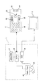
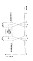
図6は、特許文献1に記載された撮像装置の構成を示すブロック図である。この撮像装置は、レンズ101と、CCD撮像素子102と、タイミングジェネレータ103と、AGC回路104と、A/D変換器105と、カメラ信号生成回路106と、ガンマ補正切換スイッチ110と、ガンマ補正回路107と、メモリ回路108と、加算器111,112と、D/A変換器109とを備えている。
FIG. 6 is a block diagram illustrating a configuration of the imaging apparatus described in
タイミングジェネレータ103の切換により、長時間露光と短時間露光が交互に切り換えられる。撮像素子102から出力される撮像信号は、AGC回路104でゲイン調整が行われ、A/D変換部105でディジタル信号に変換される。カメラ信号生成回路106で、輝度信号と色差信号に分離される。ガンマ補正切換スイッチ110がタイミングジェネレータ103と同期して切り換えられ、ガンマ特性A及びガンマ特性Bの一方が選択される。ガンマ補正回路107は、ガンマ補正切換スイッチ110の設定に応じた特性のガンマ補正を行う。
By switching the
メモリ回路108から短時間露光信号が出力されるときは、加算器111によりオフセットが加算され、加算器111の出力信号は、加算器112によりガンマ補正回路107の出力信号に加算される。そして、D/A変換器109によりアナログ信号に変換されて出力される。
When the short-time exposure signal is output from the
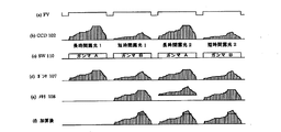
図6の撮像装置では、図7(b)に示す長時間時間露光信号及び短時間露光信号がCCD撮像素子102から出力され、ガンマ補正回路107の出力信号は、それぞれ信号(c)のようになる。その結果、加算器112の出力信号は、(f)のようになる。
In the image pickup apparatus of FIG. 6, the long time exposure signal and the short time exposure signal shown in FIG. 7B are output from the CCD
この方法では、長時間露光信号の輝度レベルをしきい値と比較して、しきい値よりも輝度レベルが高いハイライト状態の領域に短時間露光信号を用いている。しかしながら、この比較を画素毎に行うと、しきい値に近い輝度の画素が集まった領域では長時間露光信号と短時間露光信号とが混じってしまい、かえって見づらくなる。そのためハイライトの領域を判別する場合は、画素毎ではなく一定の領域に渡って平均した輝度レベルを用いて、その領域全体のハイライト状態を判別している。
ところで、交差点を監視する際、交差点全体を見渡す位置に監視カメラを設けたような場合、信号のランプは点光源となって撮像される。このとき信号のランプは輝度が高くハイライトで色が判別できない。 By the way, when monitoring an intersection, when a monitoring camera is provided at a position overlooking the entire intersection, the signal lamp is imaged as a point light source. At this time, the lamp of the signal has high brightness and the color cannot be distinguished due to highlight.
交差点の監視では信号が赤かどうかが重要であるが、ランプがハイライト状態で色がわからないと、信号の状態がわからず監視に不適である。
しかし信号のランプはこのような監視の状態では点光源なので領域が狭く、従来の広ダイナミックレンジの撮像装置ではハイライト状態と判別できない。このように従来の広ダイナミックレンジの撮像装置は、点光源を十分識別できず十分な撮像ができないという問題があった。
When monitoring intersections, it is important whether the signal is red or not. If the lamp is highlighted and the color is not known, the signal status is unknown and it is not suitable for monitoring.
However, since the signal lamp is a point light source in such a monitoring state, the area is narrow, and a conventional wide dynamic range imaging device cannot distinguish the highlight state. As described above, the conventional wide dynamic range imaging device has a problem that the point light source cannot be sufficiently identified and sufficient imaging cannot be performed.
本発明は、以上の点に鑑みなされたもので、短時間露光信号を用いる領域を予め指定しておき、その指定に従って長時間露光信号と短時間露光信号とを用いる構成としダイナミックレンジの広い撮像装置を提供することを目的とする。 The present invention has been made in view of the above points. An area in which a short-time exposure signal is used is designated in advance, and the long-time exposure signal and the short-time exposure signal are used in accordance with the designation, thereby imaging with a wide dynamic range. An object is to provide an apparatus.
本発明は、上記課題を解決するために、以下に記載の手段よりなる。
すなわち、
撮像する領域の一部分にハイライト領域を含む被写体を撮像する際、受光量を変化させて撮像した複数の映像信号を得た後、前記複数の映像信号を合成して前記被写体の映像信号を得るようにした撮像装置であって、
前記被写体を撮影するための撮像手段と、
前記ハイライト領域を設定する領域設定手段と、
前記撮像手段に第1の露光時間を供給し第1の画像を撮像する第1の露光時間設定手段と、
前記撮像手段に前記第1の露光時間より長い第2の露光時間を供給し第2の画像を撮像する第2の露光時間設定手段と、
前記領域設定手段で設定した領域に基づいて前記第1の画像と前記第2の画像とを合成する画像合成手段と
を備えることを特徴とする撮像装置。
In order to solve the above problems, the present invention comprises the following means.
That is,
When imaging a subject that includes a highlight area in a part of the imaging area, obtaining a plurality of video signals obtained by changing the amount of received light, and then synthesizing the plurality of video signals to obtain the video signal of the subject An imaging apparatus configured as described above,
Imaging means for photographing the subject;
Area setting means for setting the highlight area;
First exposure time setting means for supplying a first exposure time to the imaging means and capturing a first image;
Second exposure time setting means for supplying a second exposure time longer than the first exposure time to the image pickup means to pick up a second image;
An image pickup apparatus comprising: an image composition unit configured to compose the first image and the second image based on the region set by the region setting unit.
本発明の「撮像装置」によれば、短時間露光信号を用いる領域を予め指定しておき、その指定に従って長時間露光信号と短時間露光信号とを用いる構成としたので、点光源でも十分な撮像が可能となる撮像装置を提供することができる。 According to the “imaging device” of the present invention, the area using the short-time exposure signal is designated in advance, and the long-time exposure signal and the short-time exposure signal are used according to the designation. An imaging device capable of imaging can be provided.
以下、本発明に係る撮像装置の発明を実施するための最良の形態につき、好ましい実施例により説明する。
図1に、本実施例に適用される撮像装置の概略構成を示し、図面を参照し、その動作について述べる。
The best mode for carrying out the invention of the imaging apparatus according to the present invention will be described below with reference to preferred embodiments.
FIG. 1 shows a schematic configuration of an imaging apparatus applied to the present embodiment, and the operation thereof will be described with reference to the drawings.
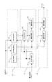
同図に示す広ダイナミックレンジ撮像装置は、撮像部13、ハイライト処理部14、雲台駆動部15、カメラCPU16、内蔵メモリ17よりなるカメラ雲台を複合した複合型カメラ1(以下、コンビネーションカメラと記す)と、ジョイスティック21、テンキー22、TELEボタン23、WIDEボタン24、メニューボタン25、及びセットボタン26よりなるコントローラ2とより構成される。コンビネーションカメラ1とコントローラ2はケーブルで接続され、RS−485などの通信プロトコルが用いられ、コンビネーションカメラ1の動作はコントローラ2によって制御される。広ダイナミックレンジ撮像装置の映像出力はモニタ3に入力される。
The wide dynamic range imaging apparatus shown in FIG. 1 includes a composite camera 1 (hereinafter referred to as a combination camera) in which a camera platform including an
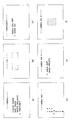
最初に、撮像を開始する前にハイライト領域を設定する。その設定方法について述べる。図2に、ハイライト領域設定時にモニタ3に順次表示されるそれぞれの画面(a)〜(f)を示し、説明する。
First, a highlight area is set before imaging starts. The setting method is described. FIG. 2 shows and explains the respective screens (a) to (f) sequentially displayed on the
まず、使用者はコントローラ2のジョイスティック21を操作して撮像装置をパン、チルト方向に駆動し、ハイライト領域として指定すべき領域がほぼ画面中央に来るよう操作する。例えば信号のランプが画面の隅に映っている場合、ジョイスティック21を操作して信号のランプが画面の中央に来るよう操作する。そして、コントローラ2のメニューボタン25を操作し、画面(a)の「MENU」画面を表示する。
First, the user operates the
同図のモニタ3に表示される画面(a)は、コントローラ2のメニューボタン25を操作したときに表示されるメニュー画面である。メニューモードとしては撮像部13のフォーカス制御に係る制御、撮影画像の明るさ制御にアイリスモード、撮影画像の色温度に係るホワイトバランス、及びハイライト領域の設定に係るハイライトモードがある。
A screen (a) displayed on the
使用者はジョイスティック21を操作し、「 > 」のマークにより表示されるカーソルを上下に動かし、「HIGHLIGHT」を選択し、セットボタン26を押す。画面(b)のID(Identification)の入力要求が表示される。使用者は予め登録されているIDナンバーをテンキー22を操作して入力する。
The user operates the
入力されたIDが登録されている正規の使用者のものと一致するとして検出された場合は、画面(c)の「HIGHLIGHT」画面がモニタ3に表示される。ジョイスティック21を用いてカーソルを動かし、「HIGHLIGHT」画面の中から「AREA NUMBER」を選択してセットボタン26を押す。画面(d)の「AREA NUMBER」画面が表示される。
When it is detected that the input ID matches that of a registered regular user, the “HIGHLIGHT” screen of screen (c) is displayed on the
本実施例では、ひとつのコンビネーションカメラにつき、8つのハイライト領域を設定可能である。既に設定されているハイライト領域があるときには「AREA NUMBER」画面の数字の横に「*」印が表示される。この例では1から3までのハイライト領域が既に設定されているので、マーク「 > 」を移動させ、新たなハイライト領域の番号4を選択する。
In this embodiment, eight highlight areas can be set for one combination camera. When there is a highlight area that has already been set, an “*” mark is displayed next to the number on the “AREA NUMBER” screen. In this example, since the highlight areas from 1 to 3 are already set, the mark “>” is moved and the
次に、セットボタン26を押し、画面(e)の「AREA NO4」の画面を表示させる。そして、「AREA NO4」の画面で「AREA EDIT」を選択してセットボタン26を押す。その操作により画面(f)が表示される。画面(f)はハイライト領域を設定するため画面である。
Next, the
画面(f)の中央に半透明の領域が表示される。ジョイスティック21を用い、領域を上下左右に移動する。撮像部13が撮影している画面の、ハイライト領域として設定すべき位置に合わせる。さらにTELEボタン23を押して領域を拡大し、又はWIDEボタン24を押して領域を縮小する。表示される領域がハイライト領域を含むよう、領域を設定する。
A translucent area is displayed in the center of the screen (f). The
ハイライト領域を設定した後にセットボタン26を押し、決定する。その決定に従い、カメラCPU16は雲台駆動部15に内蔵されている図示しない角度センサから、パンに係る角度情報、及びチルトに係る角度情報のデータを得る。
After setting the highlight area, the
一方、ハイライト領域は画面の中央部分から移動された位置に設定されている場合もあるため、水平方向の移動量を水平方向の角度に変換し上記水平角度を補正し、同様に垂直方向の移動量を基に上記垂直角度のデータを補正する。それらの補正された角度データにより、ハイライト領域がモニタ画面の中央に表示されるための角度データとして得られている。 On the other hand, since the highlight area may be set at a position moved from the center of the screen, the horizontal movement amount is converted into a horizontal angle to correct the horizontal angle, and the vertical direction is similarly changed. The vertical angle data is corrected based on the amount of movement. From these corrected angle data, the highlight area is obtained as angle data for displaying in the center of the monitor screen.
補正された水平及び垂直の角度データ、及びハイライト領域に係る大きさ(視野角)のデータはエリアナンバと共に内蔵メモリ17に記憶される。
次に領域の設定が完了すると撮像装置をパン、チルト方向に駆動して撮像を開始する。まずコントローラ2のジョイスティック21が操作されると、その操作に従って発生される撮像部13の視野角を左右に回転させるためのパン信号、又は視野角を上限に変更するためのチルト信号はカメラCPU16に供給される。それらのパン信号及びチルト信号はカメラCPU16において撮像部13が固定されている雲台の方向を変更するための駆動信号として生成される。
The corrected horizontal and vertical angle data and the size (viewing angle) data relating to the highlight area are stored in the built-in
Next, when the region setting is completed, the imaging apparatus is driven in the pan and tilt directions to start imaging. First, when the
駆動信号は雲台駆動部15に供給され、その雲台駆動部15は左右及び上下に方向を変更する。雲台及び撮像部13は雲台駆動部15と共に方向を変えながら画像を撮影する。撮影された画像はモニタ3に表示される。
The drive signal is supplied to the camera
撮像部13はまず、短時間の露光により視野領域内全体の画像を撮影し、短時間露光信号を得る。短時間とは例えば1/1000秒であり、撮像素子の電荷蓄積時間を制御することで露光時間を制御することができる。このようにして撮像された短時間露光信号は画像メモリ17の短時間記録部172に記憶される。
First, the
撮像部13は短時間露光の撮影の後、NTSC方式の場合は1/60秒後、PAL方式の場合は1/50秒後に、全体の画像を長時間露光で撮影し、画像メモリ17の長時間記録部173に記憶される。ハイライト領域のパン及びチルトに係る方向情報、大きさに係る情報も内蔵メモリ17に記憶される。方向情報及びサイズ情報は複数のハイライト領域についてそれぞれの管理番号が付され、内蔵メモリ17の角度記憶部に記憶される。
The
その後、コントローラ2が操作されてハイライト領域を含む領域が撮影されるときには、ハイライト領域部分が撮影されていることをカメラCPU16により検出する。画像置換部142はまず長時間記憶部173に記憶された長時間露光で撮影した画像を読み込み、次にハイライト処理部14により、検出されたハイライト領域を短時間記憶部172に記憶されている短期間露光で撮影した画像に置換する。このように画像置換部142で生成された画像は、NTSC方式の場合1/60秒ごと、PAL方式の場合1/50秒ごとに出力され、モニタ3に供給されて表示される。即ち、1フレームの間に短時間露光による撮影と長時間露光による撮影をそれぞれ行い、それらを設定したハイライト領域に基づいて合成して通常のフレームレートで画像を出力するものである。
Thereafter, when the
長時間露光画像に対する短時間露光画像の置換は、撮影される画像に違和感を与えることなく行う必要がある。具体的には、はめ込む画像のエッジ部の位置合せ誤差を小さくする、エッジ部の平滑化処理を行い境界部分を目立たなくする。さらに好ましくは、撮影されている画像に対して同じ明るさ、同じコントラスト、及び同じ色温度の画像になるように画質を補正した後に重ね合わせる(置換する)。 The replacement of the short-exposure image with the long-exposure image must be performed without giving a sense of incongruity to the captured image. Specifically, the boundary portion is made inconspicuous by performing edge portion smoothing processing to reduce the alignment error of the edge portion of the image to be inserted. More preferably, the captured image is superposed (replaced) after the image quality is corrected so that the image has the same brightness, the same contrast, and the same color temperature.
カメラCPU16は、撮像部13で撮影された画像と内蔵メモリ17に記憶される画像とを比較することにより補正すべき条件を検出し、検出された条件に従って補正した短時間露光信号をハイライト処理部14に供給する。
The
ここで、表示位置の修正された短時間露光の画像と撮影部13から入力された長時間露光の画像は画像比較部162で比較され、明るさ、コントラスト、及び色温度の異なりが検出される。位置補正部164で表示位置の補正された短時間露光の画像は、画像補正部163で撮像部13により撮影された画像の画質と同様の画像に補正され画像置換部142に供給される。
Here, the short-exposure image with the corrected display position and the long-exposure image input from the photographing
画像置換部142では、撮像部13により撮影されたハイライト領域の画像は、画像補正部163により画質の補正された短時間露光の画像に置換される。ここで、画像の置換される部分に画像位置の誤差があるとその部分の画像は2重の画像になる、又は境界部の欠けた画像になり、不自然である。
In the
そこで、輪郭処理部141では角度記憶部171から供給される角度情報を基にハイライト領域部の表示される位置を求め、その求められた境界線における画像を、境界線で囲まれる部分の外側から内側にかけて徐々に減衰させるようにした境界線のソフト化処理を行う。その境界線の逆特性によるソフト化処理が画像補正部163でなされる。
Therefore, the
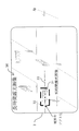
図4に、撮像画像のハイライト領域をソフト化処理された短時間露光の画像に置換する場合の画面例を示す。図4においては、信号全体をハイライト領域として設定する例を示しているが、このほか信号のライトのみを設定することも好適である。 FIG. 4 shows an example of a screen when the highlighted area of the captured image is replaced with a short-time exposure image subjected to software processing. Although FIG. 4 shows an example in which the entire signal is set as a highlight area, it is also preferable to set only signal writing.
同図において、モニタ3に撮像画像30が表示されている。その画面の中心部にハイライト領域が存在している。その領域を短時間露光の画像31で置換して表示する。短時間露光の画像31の境界を目立たなくするために、ソフト化処理された境界32を介して短時間露光の画像31を表示する。
In the figure, a captured
次に、境界のソフト化処理についてさらに述べる。
図5に、図4で示した画面3を構成する、2点鎖線で示した1本の走査線33における画像信号とその減衰量に係るレベル係数の関係を示す。横軸は画面の横位置であり、h2〜h5がハイライト領域である。h1〜h3及びh4〜h6は境界32のそれぞれの部分である。
Next, the boundary softening process will be further described.
FIG. 5 shows a relationship between an image signal in one
撮像画像30の画像信号は画面3の左端h0からh1までは撮像された信号のレベルはそのままである。h1〜h3の間で減衰される。h3〜h4は減衰された黒レベルであり、h4〜h5で徐々に増加しh5で元の信号レベルになる。h6から画面右端のh9までは撮像された状態の信号レベルである。
As for the image signal of the captured
短時間露光の画像31のレベル特性は撮像画像30と反対の特性(減衰特性)を示している。それらのレベル特性が与えられた撮像画像30と静止画31を画像置換部142で加算すると、境界領域がソフト化(フェードイン及びフェードアウト)されて撮像画像30に静止画31が挿入された合成画像として得られる。境界のソフト化処理された合成画像は異なる時刻に撮影された画質の異なる2つの画像、又は多少の位置誤差を含む2つの画像に対して違和感を少なくするものである。
The level characteristic of the short-
上述の画像補正部163における境界線のソフト化処理は短時間露光の画像の境界線で囲まれる部分の外側から内側にかけて徐々に増加させるようにしたソフト化処理であり、画像補正部163では長時間露光の画像に反対のソフト化処理した画像信号を得、画像置換部142で加算処理することにより所望の置換処理された置換監視画像が得られる。
The above-described boundary line softening process in the
以上、広ダイナミック撮像装置の概略構成と、その動作について述べた。
なお、短時間露光信号記憶部172には短時間の露光で撮像された画像を記憶するとして述べた。その画像信号はディジタル変換された画像信号であり、さらにはJPEG(Joint Photographic Coding Experts Group)などで規定される圧縮符号化された画像信号であってもよい。
The general configuration and operation of the wide dynamic imaging apparatus have been described above.
It has been described that the short-time exposure
また、雲台駆動部15に取り付けられる角度検出素子の誤差を吸収するため、撮像画像に対する静止画像の位置検出を動きベクトル法を用いて行い、静止画の位置のファインチューニングを行う方法がある。動きベクトルの検出はMPEG(Moving Picture Experts Group)を中心として広く用いられており、量産されている素子を用い、少ないコスト負担で性能を向上させることができる。
Further, in order to absorb the error of the angle detection element attached to the pan
さらに、上述のハイライト領域は矩形による領域として述べた。ハイライト領域は矩形以外の例えば平行四辺形、台形、多角形、丸、及び楕円など、形を所定のパラメータで一意に決められる形状を用いてもよく、その形状及びサイズに係るパラメータを角度記憶部171に記憶するようにしてもよい。形状データをジョイスティック21を操作して作成し、内蔵メモリ17に記憶し、それを用いるようにしてもよい。
Furthermore, the highlight area described above has been described as a rectangular area. The highlight area may be a shape other than a rectangle, such as a parallelogram, trapezoid, polygon, circle, and ellipse, whose shape is uniquely determined by a predetermined parameter, and the angle and the parameters related to the shape and size are stored as an angle. You may make it memorize | store in the
また、本発明は広ダイナミックレンジ撮像装置を制御する、カメラCPU16にロードされるプログラムを含むものである。そのプログラムは次のようなものである。
すなわち、
撮像する領域の一部分にハイライト領域を含む被写体を撮像する際、受光量を変化させて撮像した複数の映像信号を得た後、前記複数の映像信号を合成して前記被写体の映像信号を得るようにした撮像装置を制御する監視画像生成用プログラムであって、
前記被写体を撮影するための撮像ステップと、
前記ハイライト領域を設定する領域設定ステップと、
前記撮像ステップに第1の露光時間を供給し第1の画像を撮像する第1の露光時間設定ステップと、
前記撮像ステップに前記第1の露光時間より長い第2の露光時間を供給し第2の画像を撮像する第2の露光時間設定ステップと、
前記領域設定ステップで設定した領域に基づいて前記第1の画像と前記第2の画像とを合成する画像合成ステップと
を備えることを特徴とする監視画像生成用プログラムである。
Further, the present invention includes a program loaded on the
That is,
When imaging a subject that includes a highlight area in a part of the imaging area, obtaining a plurality of video signals obtained by changing the amount of received light, and then synthesizing the plurality of video signals to obtain the video signal of the subject A monitoring image generation program for controlling an imaging apparatus configured as described above,
An imaging step for photographing the subject;
An area setting step for setting the highlight area;
A first exposure time setting step of supplying a first exposure time to the imaging step and capturing a first image;
A second exposure time setting step of capturing a second image by supplying a second exposure time longer than the first exposure time to the imaging step;
A monitoring image generation program comprising: an image synthesis step of synthesizing the first image and the second image based on the area set in the area setting step.
撮像される画像の所定部分の画像を、異なる露光時間で撮影した同一視野角の画像に置換することによりダイナミックレンジの広い監視カメラ装置の実現に利用できる。 By replacing an image of a predetermined portion of the image to be captured with an image with the same viewing angle taken at a different exposure time, it can be used to realize a surveillance camera device with a wide dynamic range.
1…コンビネーションカメラ
2…コントローラ
3…モニタ
13…撮像部
14…マスク処理部
15…雲台駆動部
16…カメラCPU
17…内蔵メモリ
21…テンキー
22…ジョイスティック
23…TELEボタン
24…WIDEボタン
25…メニューボタン
26…セットボタン
30…長時間露光の画像
31…短時間露光の画像
32…境界
33…走査線
141…輪郭処理部
142…画像置換部
161…角度比較部
162…画像比較部
163…画像補正部
171…角度記憶部
172…短時間露光信号記憶部
DESCRIPTION OF
17 ... Built-in
Claims (1)
前記被写体を撮影するための撮像手段と、
前記ハイライト領域を設定する領域設定手段と、
前記撮像手段に第1の露光時間を供給し第1の画像を撮像する第1の露光時間設定手段と、
前記撮像手段に前記第1の露光時間より長い第2の露光時間を供給し第2の画像を撮像する第2の露光時間設定手段と、
前記領域設定手段で設定した領域に基づいて前記第1の画像と前記第2の画像とを合成する画像合成手段と
を備えることを特徴とする撮像装置。
When imaging a subject that includes a highlight area in a part of the imaging area, obtaining a plurality of video signals obtained by changing the amount of received light, and then synthesizing the plurality of video signals to obtain the video signal of the subject An imaging apparatus configured as described above,
Imaging means for photographing the subject;
Area setting means for setting the highlight area;
First exposure time setting means for supplying a first exposure time to the imaging means and capturing a first image;
Second exposure time setting means for supplying a second exposure time longer than the first exposure time to the image pickup means to pick up a second image;
An image pickup apparatus comprising: an image composition unit configured to compose the first image and the second image based on the region set by the region setting unit.
Priority Applications (1)
| Application Number | Priority Date | Filing Date | Title |
|---|---|---|---|
| JP2004102841A JP2005294913A (en) | 2004-03-31 | 2004-03-31 | Imaging apparatus |
Applications Claiming Priority (1)
| Application Number | Priority Date | Filing Date | Title |
|---|---|---|---|
| JP2004102841A JP2005294913A (en) | 2004-03-31 | 2004-03-31 | Imaging apparatus |
Publications (1)
| Publication Number | Publication Date |
|---|---|
| JP2005294913A true JP2005294913A (en) | 2005-10-20 |
Family
ID=35327410
Family Applications (1)
| Application Number | Title | Priority Date | Filing Date |
|---|---|---|---|
| JP2004102841A Pending JP2005294913A (en) | 2004-03-31 | 2004-03-31 | Imaging apparatus |
Country Status (1)
| Country | Link |
|---|---|
| JP (1) | JP2005294913A (en) |
Cited By (6)
| Publication number | Priority date | Publication date | Assignee | Title |
|---|---|---|---|---|
| JP2007306447A (en) * | 2006-05-15 | 2007-11-22 | Sony Corp | Imaging apparatus, image processing method, and computer program |
| JP2008252195A (en) * | 2007-03-29 | 2008-10-16 | Yamaha Corp | CMOS solid-state imaging device |
| JP2009017157A (en) * | 2007-07-04 | 2009-01-22 | Omron Corp | Image processing apparatus and method, and program |
| KR100892972B1 (en) | 2007-05-29 | 2009-04-10 | 한국과학기술연구원 | Image signal processing method with wide dynamic range using physical characteristics of image sensor |
| JP2010272094A (en) * | 2009-05-25 | 2010-12-02 | Olympus Corp | Image acquisition device, image composition method, and microscope system |
| JP2012200025A (en) * | 2008-03-14 | 2012-10-18 | Omron Corp | Image processing apparatus |
-
2004
- 2004-03-31 JP JP2004102841A patent/JP2005294913A/en active Pending
Cited By (6)
| Publication number | Priority date | Publication date | Assignee | Title |
|---|---|---|---|---|
| JP2007306447A (en) * | 2006-05-15 | 2007-11-22 | Sony Corp | Imaging apparatus, image processing method, and computer program |
| JP2008252195A (en) * | 2007-03-29 | 2008-10-16 | Yamaha Corp | CMOS solid-state imaging device |
| KR100892972B1 (en) | 2007-05-29 | 2009-04-10 | 한국과학기술연구원 | Image signal processing method with wide dynamic range using physical characteristics of image sensor |
| JP2009017157A (en) * | 2007-07-04 | 2009-01-22 | Omron Corp | Image processing apparatus and method, and program |
| JP2012200025A (en) * | 2008-03-14 | 2012-10-18 | Omron Corp | Image processing apparatus |
| JP2010272094A (en) * | 2009-05-25 | 2010-12-02 | Olympus Corp | Image acquisition device, image composition method, and microscope system |
Similar Documents
| Publication | Publication Date | Title |
|---|---|---|
| JP5144481B2 (en) | Imaging apparatus and imaging method | |
| JP4919160B2 (en) | Imaging apparatus and program thereof | |
| US7843494B2 (en) | Image taking apparatus and control method therefor | |
| JP3530907B2 (en) | Digital camera | |
| JP5656579B2 (en) | Image pickup apparatus capable of correcting deterioration of image quality caused by optical member, control method for image pickup apparatus, and program | |
| US7414657B2 (en) | Image capture apparatus having display displaying correctly oriented images based on orientation of display, image display method of displaying correctly oriented images, and program | |
| JP5872834B2 (en) | Imaging apparatus, imaging method, and imaging program | |
| JP2008236534A (en) | Digital camera, information display method, and information display control program | |
| JP2001245204A (en) | Imaging device and luminance distribution display method | |
| US7423671B2 (en) | Image pickup apparatus and photographing method with image angle correction for combining image data | |
| WO2008056561A1 (en) | Imaging device | |
| JP2010081260A (en) | Imaging apparatus and program therefor | |
| JP4167200B2 (en) | Signal processing apparatus, signal processing method, and digital camera | |
| JP4406461B2 (en) | Imaging device | |
| JP2009253669A (en) | Image processing device and digital camera | |
| JP2005294913A (en) | Imaging apparatus | |
| JP2004096392A (en) | Digital camera | |
| JP2006166358A (en) | Imaging apparatus and imaging system | |
| JP4541859B2 (en) | Camera and luminance distribution display method | |
| JP4522232B2 (en) | Imaging device | |
| JP4573158B2 (en) | Monitoring image generation method and monitoring image generation apparatus | |
| JP2008283477A (en) | Image processing apparatus and image processing method | |
| JP4547302B2 (en) | Image display device | |
| KR101298638B1 (en) | Method for processing digital image | |
| JP2019041399A (en) | Image processing apparatus, image processing method, and program |
Legal Events
| Date | Code | Title | Description |
|---|---|---|---|
| A621 | Written request for application examination |
Free format text: JAPANESE INTERMEDIATE CODE: A621 Effective date: 20060630 |
|
| A977 | Report on retrieval |
Free format text: JAPANESE INTERMEDIATE CODE: A971007 Effective date: 20081106 |
|
| A131 | Notification of reasons for refusal |
Free format text: JAPANESE INTERMEDIATE CODE: A131 Effective date: 20081111 |
|
| A02 | Decision of refusal |
Free format text: JAPANESE INTERMEDIATE CODE: A02 Effective date: 20090306 |