JP2005294911A - Television broadcast receiver - Google Patents
Television broadcast receiver Download PDFInfo
- Publication number
- JP2005294911A JP2005294911A JP2004102835A JP2004102835A JP2005294911A JP 2005294911 A JP2005294911 A JP 2005294911A JP 2004102835 A JP2004102835 A JP 2004102835A JP 2004102835 A JP2004102835 A JP 2004102835A JP 2005294911 A JP2005294911 A JP 2005294911A
- Authority
- JP
- Japan
- Prior art keywords
- video
- audio
- signal
- television broadcast
- video signal
- Prior art date
- Legal status (The legal status is an assumption and is not a legal conclusion. Google has not performed a legal analysis and makes no representation as to the accuracy of the status listed.)
- Pending
Links
- 230000005236 sound signal Effects 0.000 claims abstract description 30
- 230000001360 synchronised effect Effects 0.000 claims description 7
- 238000009434 installation Methods 0.000 abstract description 5
- 238000010586 diagram Methods 0.000 description 4
- 230000005540 biological transmission Effects 0.000 description 1
Images
Landscapes
- Television Receiver Circuits (AREA)
Abstract
Description
本発明は、テレビジョン放送受信装置に関する。 The present invention relates to a television broadcast receiving apparatus.
テレビジョン放送受信装置において、映像信号処理回路と音声信号処理回路とは全く別個の構成をとっているため、テレビジョン放送波から映像信号と音声信号とを復調したとき、復調された各々の信号のタイミングがずれてしまう。そのため、映像信号に対して音声信号の相対的遅延量を調整することが行われている(例えば、特許文献1参照。)。 In the television broadcast receiver, the video signal processing circuit and the audio signal processing circuit have completely separate configurations. Therefore, when the video signal and the audio signal are demodulated from the television broadcast wave, each demodulated signal Will be out of timing. Therefore, the relative delay amount of the audio signal is adjusted with respect to the video signal (see, for example, Patent Document 1).
また、テレビジョン放送においては、衛星中継など伝送系で映像信号と音声信号との時間的ずれが生じる場合がある。そのため、受信側で映像信号と音声信号とのずれを映像モニタで視覚的に観察し、両者の同期をとる提案がされている(例えば、特許文献2参照。)。 In television broadcasting, there may be a time lag between a video signal and an audio signal in a transmission system such as satellite relay. For this reason, a proposal has been made to visually observe the difference between the video signal and the audio signal on the receiving side on a video monitor and to synchronize the two (for example, see Patent Document 2).
ところで、上述の特許文献はいずれも映像信号と音声信号との相対遅延量をなくすることを目的としている。近年のモニタは映像信号のデジタル処理が一般的になっており、入力画像信号が出画されるまでの処理時間が大きい傾向にある。また、当然この映像信号の処理時間はモニタの機種毎に異なるものである。 By the way, all the above-mentioned patent documents are aimed at eliminating the relative delay amount between the video signal and the audio signal. In recent years, digital processing of video signals is common in monitors, and the processing time until an input image signal is output tends to be long. Of course, the processing time of the video signal differs depending on the monitor model.
従って、テレビジョン放送受信装置に接続するモニタによっては映像信号と音声信号とのずれが生じてしまい視聴に際して違和感が発生するという問題があった。
また、テレビジョン放送受信装置にアナログ音声出力、デジタル音声出力が装備されている場合など複数の音声出力系統が設けられている場合、出力系統毎に映像信号と音声信号とのずれが生じてしまい視聴に際して違和感が発生するという問題があった。
Therefore, depending on the monitor connected to the television broadcast receiving apparatus, there is a problem that a difference between the video signal and the audio signal occurs, and a sense of incongruity occurs during viewing.
In addition, when a plurality of audio output systems are provided, such as when the television broadcast receiver is equipped with analog audio output and digital audio output, a deviation between the video signal and the audio signal occurs for each output system. There was a problem that a sense of incongruity occurred during viewing.
本発明は、以上の点に鑑みなされたもので、視聴者の映像機器、音響機器の設置形態に関係なく映像信号と音声信号との同期をとることが可能なテレビジョン放送受信装置を提供することを目的とする。 The present invention has been made in view of the above points, and provides a television broadcast receiver capable of synchronizing a video signal and an audio signal regardless of the installation form of a viewer's video equipment and audio equipment. For the purpose.
本発明は、上記課題を解決するために、以下に記載手段よりなる。
すなわち、
少なくとも一組の映像信号の外部出力端子及び音声信号の外部出力端子を備えたテレビジョン放送受信装置であって、
前記映像信号の外部出力端子に接続される外部映像表示装置における映像信号の処理に要する遅延時間に同一の音声遅延を行う遅延手段を前記音声信号出力手段の前段に備え、
前記一組の外部出力端子に接続された前記外部映像表示装置で表示される映像の変化に同期するように音声を出力可能としたことを特徴とするテレビジョン放送受信装置。
In order to solve the above problems, the present invention comprises the following means.
That is,
A television broadcast receiver comprising at least one set of video signal external output terminals and audio signal external output terminals,
A delay unit that performs the same audio delay in a delay time required for processing of the video signal in the external video display device connected to the external output terminal of the video signal is provided in the preceding stage of the audio signal output unit,
A television broadcast receiving apparatus characterized in that audio can be output so as to be synchronized with a change in video displayed on the external video display device connected to the set of external output terminals.
本発明の「テレビジョン放送受信装置」によれば、視聴者の映像機器、音響機器の設置形態に関係なく映像信号と音声信号との同期をとることが可能なテレビジョン放送受信装置を提供することができる。 According to the “television broadcast receiving apparatus” of the present invention, there is provided a television broadcast receiving apparatus capable of synchronizing a video signal and an audio signal regardless of the installation form of the viewer's video equipment and audio equipment. be able to.
以下、本発明に係るテレビジョン放送受信装置の発明を実施するための最良の形態につき、好ましい実施例により説明する。 The best mode for carrying out the invention of the television broadcast receiving apparatus according to the present invention will be described below with reference to preferred embodiments.
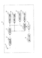
図1は実施例1に適用されるテレビジョン放送受信装置の構成を示した概略ブロック図である。同図に示すように、テレビジョン放送受信装置10はアンテナ11、復調装置12、増幅装置13、映像出力装置14、音声出力装置15、映像出力端子16、遅延回路17、音声出力端子18、操作入力部19、CPU9から構成されている。
FIG. 1 is a schematic block diagram showing the configuration of a television broadcast receiving apparatus applied to the first embodiment. As shown in the figure, the
アンテナ11により受信されたテレビジョン放送波は、周知の復調装置12により映像信号と音声信号とを復調したのち増幅装置13に供給される。増幅装置13は供給された映像信号と音声信号とを夫々増幅してCRTである映像出力装置14、内部スピーカである音声出力装置15に供給する。当然、これら内部装置に対する映像信号と音声信号とは従来通り同期がとれているものである。
The television broadcast wave received by the
一方、増幅装置13は供給された映像信号と音声信号とを夫々増幅して映像信号を映像出力端子16に供給する。音声信号は遅延回路17を介して音声出力端子18に供給する。このとき、外部接続装置の状況に合わせ、CPU9は操作入力部19からの設定により遅延回路17の遅延時間の制御を行うようにしている。映像出力端子16及び音声出力端子18から出力される映像信号と音声信号とは同期していない状態となるが、視聴者の機器設置に対応しているので、最終的に視聴する映像信号と音声信号とは同期したものとなる。
設定の状態を映像出力装置14に表示させるように構成してもよい。
On the other hand, the
The setting state may be displayed on the
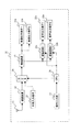
次に複数の外部出力端子を備えた実施例2について説明する。図2は実施例2に適用されるテレビジョン放送受信装置の構成を示した概略ブロック図である。同図に示すように、テレビジョン放送受信装置20はアンテナ11、復調装置12、増幅装置13、映像出力端子(1)21a、映像出力端子(2)21b、遅延回路(1)23a、遅延回路(2)23b、音声出力端子(1)22a、音声出力端子(2)22b、外部入力端子25、操作入力部19、CPU24、セレクタ26から構成されている。、
Next, a second embodiment having a plurality of external output terminals will be described. FIG. 2 is a schematic block diagram showing the configuration of a television broadcast receiving apparatus applied to the second embodiment. As shown in the figure, the
アンテナ11により受信されたテレビジョン放送波は、周知の復調装置12により映像信号と音声信号とを復調したのち増幅装置13に供給される。増幅装置13は供給された映像信号と音声信号とを夫々増幅して、組である映像出力端子(1)21a、及び遅延回路(1)23aを介して音声出力端子(1)22aに供給する。同時に、映像出力端子(2)21b、及び遅延回路(2)23bを介して音声出力端子(2)22bに供給する。
The television broadcast wave received by the
このとき、夫々の組の出力端子が接続されている外部接続装置の状況に合わせ、CPU24は操作入力部19からの設定により遅延回路(1)23a、遅延回路(2)23bの遅延時間の制御を行うようにしている。映像出力端子(1)21a、及び音声出力端子(1)22aから出力される映像信号と音声信号とは、また、映像出力端子(2)21b、及び音声出力端子(2)22bから出力される映像信号と音声信号とは同期していない状態となるが、視聴者の機器設置に対応しているので、最終的に視聴する映像信号と音声信号とは同期したものとなる。
At this time, the
さらに、外部入力端子25から入来する外部信号をセレクタ26で切り換えられるよう構成しており、外部信号に関しても視聴者の機器設置に対応できるようにしている。また、増幅装置13を複数用いる構成としてもよく、設定の状態を映像出力端子(1)21a、映像出力端子(2)21bに夫々表示させるように構成してもよい。
Furthermore, an external signal coming from the
10,21…テレビジョン放送受信装置
11…アンテナ
12…復調装置
13…増幅装置
14…映像出力装置
15…音声出力装置
16,21a,21b…映像出力端子
17,23a,23b…遅延回路
18,22a,22b…音声出力端子
19…操作入力部
9,24…CPU
25…外部入力端子
26…セレクタ
DESCRIPTION OF
25 ...
Claims (1)
前記映像信号の外部出力端子に接続される外部映像表示装置における映像信号の処理に要する遅延時間に同一の音声遅延を行う遅延手段を前記音声信号出力手段の前段に備え、
前記一組の外部出力端子に接続された前記外部映像表示装置で表示される映像の変化に同期するように音声を出力可能としたことを特徴とするテレビジョン放送受信装置。
A television broadcast receiver comprising at least one set of video signal external output terminals and audio signal external output terminals,
A delay unit that performs the same audio delay in a delay time required for processing of the video signal in the external video display device connected to the external output terminal of the video signal is provided in the preceding stage of the audio signal output unit,
A television broadcast receiving apparatus characterized in that audio can be output so as to be synchronized with a change in video displayed on the external video display device connected to the set of external output terminals.
Priority Applications (1)
| Application Number | Priority Date | Filing Date | Title |
|---|---|---|---|
| JP2004102835A JP2005294911A (en) | 2004-03-31 | 2004-03-31 | Television broadcast receiver |
Applications Claiming Priority (1)
| Application Number | Priority Date | Filing Date | Title |
|---|---|---|---|
| JP2004102835A JP2005294911A (en) | 2004-03-31 | 2004-03-31 | Television broadcast receiver |
Publications (1)
| Publication Number | Publication Date |
|---|---|
| JP2005294911A true JP2005294911A (en) | 2005-10-20 |
Family
ID=35327408
Family Applications (1)
| Application Number | Title | Priority Date | Filing Date |
|---|---|---|---|
| JP2004102835A Pending JP2005294911A (en) | 2004-03-31 | 2004-03-31 | Television broadcast receiver |
Country Status (1)
| Country | Link |
|---|---|
| JP (1) | JP2005294911A (en) |
-
2004
- 2004-03-31 JP JP2004102835A patent/JP2005294911A/en active Pending
Similar Documents
| Publication | Publication Date | Title |
|---|---|---|
| JP2007110761A (en) | Antenna switching device | |
| CA1247232A (en) | Video noise reduction in picture-in-picture television receiver | |
| KR100789548B1 (en) | Synchronization apparatus and method for audio output of the TV | |
| US6724432B2 (en) | Apparatus and method for transmitting audio over a dedicated video line | |
| US20100231801A1 (en) | Automatic gain control circuit | |
| EP1239628A2 (en) | Terminal devices synchronizing method communication system and terminal device | |
| JP2005294911A (en) | Television broadcast receiver | |
| KR100677971B1 (en) | Television Receivers and Methods for Delay Control of Audio Signals | |
| JP5075383B2 (en) | Subtitle transmission apparatus and subtitle transmission method | |
| KR20050078154A (en) | Tv broadcast advertising system and the method thereof | |
| US20090284659A1 (en) | Monitor with multiple video inputs and one video output | |
| JP3035903U (en) | Receiver having OSD non-display video output terminal | |
| JP2738703B2 (en) | Television signal delay adjustment method | |
| US20120084827A1 (en) | Image Display Apparatus and Sound Output Control Method | |
| KR100222097B1 (en) | Tv still picture outputting device by using internet module and thereof method | |
| JP3521962B2 (en) | Unit for retransmission in CATV system | |
| JPS6316206Y2 (en) | ||
| JP4068574B2 (en) | Wireless transmission apparatus and wireless transmission / reception system | |
| JP2006186454A (en) | Broadcast receiver, portable broadcast receiver | |
| KR20100046395A (en) | Method and audio signal output circiut of display device | |
| KR200361053Y1 (en) | Tv broadcast advertising system | |
| GB2376143A (en) | Broadcast data receiver system | |
| KR20070078571A (en) | Apparatus and method for synchronizing video and audio signals in AV system | |
| JP2005109664A (en) | Digital television receiver | |
| JPH08331474A (en) | Multi-system dealing receiver |