JP2005294885A - Radio module - Google Patents
Radio module Download PDFInfo
- Publication number
- JP2005294885A JP2005294885A JP2004102414A JP2004102414A JP2005294885A JP 2005294885 A JP2005294885 A JP 2005294885A JP 2004102414 A JP2004102414 A JP 2004102414A JP 2004102414 A JP2004102414 A JP 2004102414A JP 2005294885 A JP2005294885 A JP 2005294885A
- Authority
- JP
- Japan
- Prior art keywords
- antenna
- planar antenna
- wireless module
- receiving
- substrate
- Prior art date
- Legal status (The legal status is an assumption and is not a legal conclusion. Google has not performed a legal analysis and makes no representation as to the accuracy of the status listed.)
- Pending
Links
- 230000005540 biological transmission Effects 0.000 claims abstract description 44
- 239000000758 substrate Substances 0.000 claims abstract description 35
- 239000004020 conductor Substances 0.000 description 21
- 230000004048 modification Effects 0.000 description 5
- 238000012986 modification Methods 0.000 description 5
- 229910000881 Cu alloy Inorganic materials 0.000 description 2
- 238000004519 manufacturing process Methods 0.000 description 2
- 239000000463 material Substances 0.000 description 2
- -1 polytetrafluoroethylene Polymers 0.000 description 2
- 229920001343 polytetrafluoroethylene Polymers 0.000 description 2
- 239000004810 polytetrafluoroethylene Substances 0.000 description 2
- 230000002238 attenuated effect Effects 0.000 description 1
- 238000009751 slip forming Methods 0.000 description 1
Images


Landscapes
- Variable-Direction Aerials And Aerial Arrays (AREA)
- Details Of Aerials (AREA)
- Transceivers (AREA)
Abstract
Description
本発明は、無線モジュールに関し、特に誘電体導波路構造を有する無線アンテナを用いた無線モジュールに関する。 The present invention relates to a wireless module, and more particularly to a wireless module using a wireless antenna having a dielectric waveguide structure.
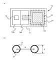
従来、電波信号を送受信する無線モジュールとして、例えば図1に示すような無線モジュール1が用いられてきた。この無線モジュール1は、内部に導波路が形成されている平面基板2と、平面基板2の上面又は下面のいずれかに設けられた平面アンテナ3と、送信装置4とを含む。平面アンテナ3と送信装置4とは、平面基板2内部の導波路を介して接続されている。図1に示す無線モジュール1は、送信装置4を用いた場合は送信ユニットとして機能し、送信装置4の代わりに受信装置を用いた場合は受信ユニットとして機能する。
Conventionally, for example, a wireless module 1 as shown in FIG. 1 has been used as a wireless module for transmitting and receiving radio signals. The wireless module 1 includes a
図1に示すような無線モジュールを用いて送受信を行う場合、通常は送信用無線モジュールと受信用無線モジュールとを並列に組み合わせて用いていた。しかしながら、このような場合、図1(c)に示すように、送信用平面アンテナ3aと受信用平面アンテナ3bとが、同一の平面基板2の同一平面上に同一方向を向いて設けられるため、例えば送信用平面アンテナ3aから電波を放射すると、その電波の一部が同時に受信用平面アンテナ3bで受信されてしまい、自ら発した電波が妨害波となって漏話等の混信を引き起こしてしまうという問題点があった。
In the case of performing transmission / reception using a wireless module as shown in FIG. 1, normally, a transmitting wireless module and a receiving wireless module are combined in parallel. However, in such a case, as shown in FIG. 1C, the transmitting
そこで本発明は、上記のような問題を鑑み、送信装置及び送信用アンテナと受信装置及び受信用アンテナとを同じ筐体内に用いても漏話等の混信を防止することができる無線モジュールを提供することを目的とする。 In view of the above problems, the present invention provides a wireless module capable of preventing crosstalk and other interference even when a transmitting device, a transmitting antenna, a receiving device, and a receiving antenna are used in the same casing. For the purpose.
上記の目的を達成するために、本発明は、請求項1記載のように、送信装置及び受信装置と、前記送信装置及び受信装置を搭載しかつ表面にアンテナ面を有すると共に、前記送信装置あるいは受信装置のいずれか一方と接続される第1のアンテナを有する平面アンテナ基板と、前記送信装置あるいは受信装置の他方と接続されると共に、前記第1のアンテナ面と同一方向に向けられかつ前記第1のアンテナ面とは異なる高さで設けられた第2のアンテナと、を有することを特徴とする無線モジュールである。このような構成によれば、第1及び第2のアンテナは同一平面上にならないように配置されるため、2つのアンテナで同時に送受信しても漏話等の混信を防止することができる。 In order to achieve the above object, according to the present invention, a transmission device and a reception device, the transmission device and the reception device are mounted, and an antenna surface is provided on a surface thereof. A planar antenna substrate having a first antenna connected to one of the receiving devices, and connected to the other of the transmitting device or the receiving device and oriented in the same direction as the first antenna surface and the first And a second antenna provided at a height different from that of the first antenna surface. According to such a configuration, since the first and second antennas are arranged so as not to be on the same plane, interference such as crosstalk can be prevented even if the two antennas transmit and receive simultaneously.
上記前記第2のアンテナは、前記受信装置又は前記送信装置のいずれかを含むユニット内に設けられている構成とすることができる。また、このユニットは、前記第2のアンテナに対する電磁波透過窓を有することが好ましい。 The second antenna may be provided in a unit including either the receiving device or the transmitting device. Moreover, it is preferable that this unit has an electromagnetic wave transmission window for the second antenna.
また、本発明は、請求項4記載のように、表面にアンテナ面を有する第1のアンテナと、裏面にアンテナ面を有する第2のアンテナとを含む平面アンテナ基板と、前記平面アンテナ基板上に載置されかつ前記第1のアンテナあるいは前記第2のアンテナのいずれか一方と接続される送信装置と、前記平面アンテナ基板上に載置されかつ前記第1のアンテナあるいは前記第2のアンテナの他方と接続される受信装置と、を有することを特徴とする無線モジュールである。このような構成によれば、2つのアンテナは平面アンテナ基板に関して相対する2つの面に配置するため、2つのアンテナで同時に送受信しても漏話等の混信を防止することができる。 According to a fourth aspect of the present invention, there is provided a planar antenna substrate including a first antenna having an antenna surface on a front surface and a second antenna having an antenna surface on a rear surface, and the planar antenna substrate. A transmitting device mounted and connected to either the first antenna or the second antenna; and the other of the first antenna or the second antenna mounted on the planar antenna substrate And a receiving device connected to the wireless module. According to such a configuration, since the two antennas are arranged on two opposite surfaces with respect to the planar antenna substrate, interference such as crosstalk can be prevented even if the two antennas transmit and receive simultaneously.
本発明によれば、送信装置及び送信用アンテナと受信装置及び受信用アンテナとを同じ筐体内に用いても漏話等の混信を防止することができる無線モジュールを実現できる。 ADVANTAGE OF THE INVENTION According to this invention, even if it uses a transmitter, a transmitting antenna, a receiver, and a receiving antenna in the same housing | casing, the radio | wireless module which can prevent interference, such as crosstalk, is realizable.
以下、本発明を実施するための最良の形態を図面と共に詳細に説明する。 Hereinafter, the best mode for carrying out the present invention will be described in detail with reference to the drawings.
まず、本発明の実施例1について図面を用いて詳細に説明する。図2は、本実施例1による無線モジュール10の送信用平面アンテナと受信用平面アンテナとの配置原理を示す断面図である。本実施例1による無線モジュール10は、内部に導波路が形成されている基板12と送信用平面アンテナ13aと受信用平面アンテナ13bとを含む。図1(c)に示すように、送信用平面アンテナ13aと受信用平面アンテナ13bとを同一平面上に同一方向を向いて設けると漏話等の混信が生じてしまうため、本実施例1による無線モジュール10は、基板12に段差14を設けて送信用平面アンテナ13aと受信用平面アンテナ13bとの厚さ方向の位置が同一平面上とならないように配置する。この段差14は、本例のように基板12に直接段差として設けるか、又は平面基板に所定の段差を形成する物体を挟み込んで形成しても良い。このように配置することによって、送信用平面アンテナ13aから放射される電波が同時に受信用平面アンテナ13bに受信されるのを大きく低減又は防止することができる。また、図2に示す送信用平面アンテナ13aと受信用平面アンテナ13bとの位置関係が逆に配置されても良い。
First, Embodiment 1 of the present invention will be described in detail with reference to the drawings. FIG. 2 is a cross-sectional view illustrating the principle of arrangement of the transmission planar antenna and the reception planar antenna of the
次に、本実施例1による無線モジュール10の適用例について図面を用いて説明する。図3は、本実施例1による無線モジュール10の構成を示す平面図及び断面図である。本実施例1による無線モジュール10は、周囲を囲む周囲導体11a及びその内部を充填する誘電体11bとからなる基板12と、受信用平面アンテナ13bを内包する受信装置14bと、送信用平面アンテナ13aと、送信装置14aとを含む。周囲導体11aは、例えば銅合金等の導体であり、誘電体11bは、例えばポリテトラフルオロエチレンである。誘電体11bの一部には、壁部材17によって囲まれた導波路18が形成されている。壁部材17は、周囲導体11aと電気的に接続された導体であり、図3(a)に示すように連続的に形成される構造又は伝送する信号の波長よりも小さい間隔で導体を間欠的に配置する構造でも良い。導波路18は、壁部材17と周囲導体11aとによって囲まれた閉空間となっている。このような構造によって、この内部に入力された電波又は信号は、開放面以外の部分から外部には漏出しないように構成されている。
Next, an application example of the
受信装置14bは、基板12上に載置され、内部に受信用平面アンテナ13bと受信回路15bとを有するユニットである。受信用平面アンテナ13bは、例えばパッチアンテナであり、受信回路15b上に重ねられるように配置されかつ電気的に接続されている。また、受信用平面アンテナ13bは、受信装置14bの筐体の上部に設けられた電磁波透過部16を通して電波を受信する。電磁波透過部16は、受信装置14bの筐体の材料とは異なる材料で形成され、電波を減衰させることなく透過させる。一方、ユニット化された送信装置14aは、送信回路15aを内包して基板12上に載置されている。送信回路15aは、基板12の内部に設けられた導波路18と給電部19を介して電気的に接続されている。送信用平面アンテナ13aは、導波管18の領域内の周囲導体11aの上面に設けられた例えばスロットアンテナである。送信回路15aは給電部19及び導波管18を通って送信用平面アンテナ13aに送信電力を供給する。
The
図3に示す無線モジュール10では、送信装置14aと受信装置14bとが同一平面上に設けられているが、送信用平面アンテナ13aが基板12の上面に設けられているのに対して、受信用平面アンテナ13bは、受信装置14bの内部で受信回路15bの分だけアンテナの厚さ方向に高く配置されている。このような構成とすることによって、本実施例1による無線モジュール10は、送信用平面アンテナ13aと受信用平面アンテナ13bとの厚さ方向の位置が同一平面上にならないように配置されるため、送信装置及び送信用アンテナと受信装置及び受信用アンテナとを同時に用いても漏話等の混信を防止することができる。
In the
次に、本実施例1による無線モジュール10の変形例について説明する。図4は、本実施例1による無線モジュール10の変形例を示している。本変形例では、無線モジュール10は、導波路18を形成する壁部材の代わりに複数の貫通孔20が等間隔に設けられている。貫通孔20は、図4(b)に示すように、直径dを有して距離D毎に設けられる。貫通孔20は内面に導体21が被覆されるか又は導体21の円筒を挿入して構成されており、無線モジュール10の周囲導体11aと電気的に接続されている。2つの貫通孔の間の距離Dは、伝送する電波信号の波長λよりも十分に小さく、貫通孔20の直径dは距離Dよりも小さいものが用いられる。このような構成とすることによって、伝送される電波信号は、2つの貫通孔20の間を通過することができなくなる。つまり、複数の貫通孔20は擬似的な壁面とみなすことができる。複数の貫通孔20を設ける構造は、無線アンテナ基板10を製造した後に加工することが可能なため、製造工程が簡略化できるとともに、製造コストを削減することも可能となる。
Next, a modification of the
以上のような構成及び動作とすることによって、本実施例1による無線モジュール10によれば、送信用平面アンテナ13aと受信用平面アンテナ13bとの厚さ方向の位置が同一平面上にならないように配置するため、送信装置及び送信用アンテナと受信装置及び受信用アンテナとを同時に用いても漏話等の混信を防止することが実現できる。
With the configuration and operation as described above, according to the
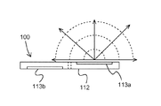
次に、本発明の実施例2について図面を用いて説明する。図5は、本実施例2による無線モジュール100の送信用平面アンテナと受信用平面アンテナとの配置を示す断面図である。本実施例1による無線モジュール100は、内部に導波路が形成されている基板112と送信用平面アンテナ113aと受信用平面アンテナ113bとを含む。図1(c)に示すように、送信用平面アンテナ113aと受信用平面アンテナ113bとを同一平面上に同一方向を向いて設けると漏話等の混信が生じてしまうため、本実施例2による無線モジュール100は、送信用平面アンテナ13aと受信用平面アンテナ13bとを基板12に関して相対する面に配置する。
Next,
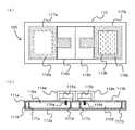
次に、本実施例2による無線モジュール100の適用例について図面を用いて説明する。図6は、本実施例2による無線モジュール100の構成を示す平面図及び断面図である。本実施例2による無線モジュール100は、周囲を囲む周囲導体111a及びその内部を充填する誘電体111bとからなる基板112と、送信用平面アンテナ113aと、送信装置114aと、受信用平面アンテナ113bと、受信装置114bとを含む。周囲導体111aは、例えば銅合金等の導体であり、誘電体111bは、例えばポリテトラフルオロエチレン等の誘電体である。誘電体111bの一部には、壁部材117aによって囲まれた導波路118aと壁部材117bによって囲まれた導波路118bとが形成されている。壁部材117a及び117bは、周囲導体111aと電気的に接続された導体であり、図6(a)に示すように連続的に形成される構造又は伝送する信号の波長よりも小さい間隔で導体を間欠的に配置する構造でも良い。導波路118a及び118bは、壁部材117a及び117bと周囲導体111aとに囲まれた閉空間となっている。このような構造によって、この内部に入力された電波又は信号は、開放面以外の部分から外部には漏出しないように構成されている。
Next, an application example of the
送信装置114aは、送信回路115aを内包して基板112上に載置されている。送信回路115aは、基板112の内部に設けられた導波路118aと給電部119aを介して電気的に接続されている。送信用平面アンテナ113aは、導波管118の領域内の周囲導体111aの下面に設けられた例えばスロットアンテナであり、送信回路115aから発せられた信号は、導波管118a及び給電部119aを通って送信用平面アンテナ113aで電波として放射される。一方、受信装置114bは、受信回路115bを内包して基板112上に載置されている。受信回路115bは、基板112の内部に設けられた導波路118bと給電部119bを介して電気的に接続されている。受信用平面アンテナ113bは、例えばスロットアンテナであり、導波管18の領域内の周囲導体11aの上面すなわち送信用平面アンテナ113aと反対側の面に設けられる。受信用平面アンテナ113bで受信された電波は、導波管118b及び給電部119bを通って受信回路115bすなわち受信装置114bに伝送される。
The
図6に示す無線モジュール100では、受信用平面アンテナ113bが基板112の上面に設けられているのに対して、送信用平面アンテナ113aは、基板112の下面すなわち受信用平面アンテナ113bの設けられた面の反対側の面に配置されている。このような構成とすることによって、本実施例2による無線モジュール100は、送信用平面アンテナ113aと受信用平面アンテナ113bとが同一方向を向かないように配置されるため、送信装置及び送信用アンテナと受信装置及び受信用アンテナとを同時に用いても漏話等の混信を防止することができる。
In the
図6に示す例では、送信装置114aと受信装置114bとが同一面上に設けられているが、例えば平面アンテナが設けられた面にそれぞれ設ける等、別々の面に設けられても良い。また、本実施例2による無線モジュール100は、導波路118a及び118bを形成する壁部材117a及び117bの代わりに図4(b)に示すような複数の貫通孔が直径dを有して距離D毎に等間隔に設けられていても良い。
In the example shown in FIG. 6, the
また、本実施例2による無線モジュール100は、例えば図7に示すように、内壁130によって仕切られた2つの部屋131a及び131bにおいて、内壁130に埋め込まれた中継器として用いることができる。すなわち、図7(a)の領域Aを拡大した図7(b)に示すように、無線モジュール100は、一方の部屋131aに対して受信用平面アンテナ113bが向けられ、もう一方の部屋131bに対して送信用平面アンテナ113aが向けられるように内壁130に設けられる。このように配置することによって、例えば内壁130に遮られたような場合であっても、部屋131a側の受信用平面アンテナ113bで受信した電波Wを部屋131b側の送信用平面アンテナ113aに伝送することが可能となる。
Further, the
以上のような構成とすることによって、本実施例2による無線モジュール100によれば、送信用平面アンテナ113aと受信用平面アンテナ113bとを基板112に関して相対する2つの面に配置するため、送信装置及び送信用アンテナと受信装置及び受信用アンテナとを同じ筐体内に用いても漏話等の混信を防止することが実現できる。また、本実施例2による無線モジュールによれば、例えば壁等の障害物に遮られたような場合であっても、受信した電波を障害物の反対側に伝送することが可能となる。
With the configuration as described above, according to the
以上の実施例から、本発明によれば、送信装置及び送信用アンテナと受信装置及び受信用アンテナとを同じ筐体内に用いても漏話等の混信を防止することができる無線モジュールを実現できる。 From the above embodiments, according to the present invention, it is possible to realize a wireless module capable of preventing crosstalk and other interference even when the transmitting device, the transmitting antenna, the receiving device, and the receiving antenna are used in the same casing.
以上、説明した実施例は、本発明を実施するための最良の形態の一つにすぎず、本発明はその主旨を逸脱しない限り種々変化及び変形して実施可能である。 The embodiment described above is only one of the best modes for carrying out the present invention, and the present invention can be implemented with various changes and modifications without departing from the gist thereof.
10、100 無線モジュール
11a、111a 周囲導体
11b、111b 誘電体
12、112 基板
13a、113a 送信用平面アンテナ
13b、113b 受信用平面アンテナ
14a、114a 送信装置
14b、114b 受信装置
15a、115a 送信回路
15b、115b 受信回路
16 電磁波透過部
20 貫通孔
d 貫通孔20の直径
D 2つの貫通孔20の間の距離
λ 伝送される電波信号の波長
W 電波
10, 100
Claims (4)
前記送信装置及び受信装置を搭載しかつ表面にアンテナ面を有すると共に、前記送信装置あるいは受信装置のいずれか一方と接続される第1のアンテナを有する平面アンテナ基板と、
前記送信装置あるいは受信装置の他方と接続されると共に、前記第1のアンテナ面と同一方向に向けられかつ前記第1のアンテナ面とは異なる高さで設けられた第2のアンテナと、を有することを特徴とする無線モジュール。 A transmitting device and a receiving device;
A planar antenna substrate having the first antenna connected to either the transmission device or the reception device, the antenna device being mounted on the surface, the antenna device being mounted on the surface;
A second antenna connected to the other of the transmission device or the reception device and oriented in the same direction as the first antenna surface and provided at a different height from the first antenna surface. A wireless module characterized by that.
前記平面アンテナ基板上に載置されかつ前記第1のアンテナあるいは前記第2のアンテナのいずれか一方と接続される送信装置と、
前記平面アンテナ基板上に載置されかつ前記第1のアンテナあるいは前記第2のアンテナの他方と接続される受信装置と、を有することを特徴とする無線モジュール。
A planar antenna substrate including a first antenna having an antenna surface on the front surface and a second antenna having an antenna surface on the back surface;
A transmission device mounted on the planar antenna substrate and connected to either the first antenna or the second antenna;
And a receiving device mounted on the planar antenna substrate and connected to the other of the first antenna and the second antenna.
Priority Applications (1)
| Application Number | Priority Date | Filing Date | Title |
|---|---|---|---|
| JP2004102414A JP2005294885A (en) | 2004-03-31 | 2004-03-31 | Radio module |
Applications Claiming Priority (1)
| Application Number | Priority Date | Filing Date | Title |
|---|---|---|---|
| JP2004102414A JP2005294885A (en) | 2004-03-31 | 2004-03-31 | Radio module |
Publications (1)
| Publication Number | Publication Date |
|---|---|
| JP2005294885A true JP2005294885A (en) | 2005-10-20 |
Family
ID=35327391
Family Applications (1)
| Application Number | Title | Priority Date | Filing Date |
|---|---|---|---|
| JP2004102414A Pending JP2005294885A (en) | 2004-03-31 | 2004-03-31 | Radio module |
Country Status (1)
| Country | Link |
|---|---|
| JP (1) | JP2005294885A (en) |
Cited By (3)
| Publication number | Priority date | Publication date | Assignee | Title |
|---|---|---|---|---|
| JP2014075682A (en) * | 2012-10-04 | 2014-04-24 | Mitsubishi Electric Corp | Substrate integrated antenna module |
| US9129941B2 (en) | 2012-06-27 | 2015-09-08 | Rohm Co., Ltd. | Wireless module with plural in-plane terminals |
| CN114270627A (en) * | 2019-08-19 | 2022-04-01 | 株式会社村田制作所 | Communication device |
-
2004
- 2004-03-31 JP JP2004102414A patent/JP2005294885A/en active Pending
Cited By (4)
| Publication number | Priority date | Publication date | Assignee | Title |
|---|---|---|---|---|
| US9129941B2 (en) | 2012-06-27 | 2015-09-08 | Rohm Co., Ltd. | Wireless module with plural in-plane terminals |
| US9893420B2 (en) | 2012-06-27 | 2018-02-13 | Rohm Co., Ltd. | Wireless module with plural in-plane terminals |
| JP2014075682A (en) * | 2012-10-04 | 2014-04-24 | Mitsubishi Electric Corp | Substrate integrated antenna module |
| CN114270627A (en) * | 2019-08-19 | 2022-04-01 | 株式会社村田制作所 | Communication device |
Similar Documents
| Publication | Publication Date | Title |
|---|---|---|
| JP7252277B2 (en) | dielectric resonator antenna module | |
| US10056693B2 (en) | Pattern shaping of RF emission patterns | |
| US10211512B2 (en) | Multi-band antenna on the surface of wireless communication devices | |
| US20200110155A1 (en) | Radar system and radar sensing system having the same | |
| JP2019088003A5 (en) | Portable communication device | |
| US20130187818A1 (en) | Antennas integrated in shield can assembly | |
| CN112234361A (en) | Housing assembly, antenna device and electronic equipment | |
| EP3721503B1 (en) | A communication device and a method in a communication device | |
| KR20100064391A (en) | Antenna having a defined gab between first and second radiating elements | |
| WO2022042239A1 (en) | Button, card tray, camera decoration accessory, and mobile terminal | |
| JP7386920B2 (en) | Electronic device with bidirectional dielectric resonator antenna | |
| JP2006033699A (en) | Combination wireless unit-antenna and manufacturing method of combination wireless unit-antenna | |
| CN113330645A (en) | Antenna device | |
| EP2645603B1 (en) | Wireless security device | |
| CN118841752A (en) | Electronic device with multi-substrate stacked patch antenna | |
| JP2005294885A (en) | Radio module | |
| JP2005294883A (en) | Radio antenna | |
| CN115863996A (en) | Electronic device with dielectric resonator antenna having non-planar sidewalls | |
| KR102617519B1 (en) | Shield can having antenna function | |
| JP2002152069A (en) | Composite communication module | |
| KR100826840B1 (en) | Embedded Antenna Module Using Conductive Dielectric | |
| KR20080056518A (en) | Mobile communication terminal | |
| JP2007329735A (en) | Wireless communication module and manufacturing method thereof | |
| WO2024090564A1 (en) | Wireless device | |
| JP2023166715A (en) | wireless communication device |
Legal Events
| Date | Code | Title | Description |
|---|---|---|---|
| A621 | Written request for application examination |
Free format text: JAPANESE INTERMEDIATE CODE: A621 Effective date: 20060913 |
|
| A977 | Report on retrieval |
Free format text: JAPANESE INTERMEDIATE CODE: A971007 Effective date: 20080206 |
|
| A131 | Notification of reasons for refusal |
Free format text: JAPANESE INTERMEDIATE CODE: A131 Effective date: 20080219 |
|
| A521 | Written amendment |
Free format text: JAPANESE INTERMEDIATE CODE: A523 Effective date: 20080331 |
|
| A131 | Notification of reasons for refusal |
Free format text: JAPANESE INTERMEDIATE CODE: A131 Effective date: 20080805 |
|
| A521 | Written amendment |
Free format text: JAPANESE INTERMEDIATE CODE: A523 Effective date: 20080917 |
|
| A131 | Notification of reasons for refusal |
Free format text: JAPANESE INTERMEDIATE CODE: A131 Effective date: 20090210 |
|
| A521 | Written amendment |
Free format text: JAPANESE INTERMEDIATE CODE: A523 Effective date: 20090327 |
|
| A02 | Decision of refusal |
Free format text: JAPANESE INTERMEDIATE CODE: A02 Effective date: 20090908 |