JP2005294491A - Carrier cleaning device - Google Patents
Carrier cleaning device Download PDFInfo
- Publication number
- JP2005294491A JP2005294491A JP2004106765A JP2004106765A JP2005294491A JP 2005294491 A JP2005294491 A JP 2005294491A JP 2004106765 A JP2004106765 A JP 2004106765A JP 2004106765 A JP2004106765 A JP 2004106765A JP 2005294491 A JP2005294491 A JP 2005294491A
- Authority
- JP
- Japan
- Prior art keywords
- carrier
- numbered
- brush
- groove
- hair
- Prior art date
- Legal status (The legal status is an assumption and is not a legal conclusion. Google has not performed a legal analysis and makes no representation as to the accuracy of the status listed.)
- Pending
Links
Images
Landscapes
- Cleaning Or Drying Semiconductors (AREA)
Abstract
【課題】 300mmウエーハ用のボックス型キャリアの内面洗浄に適用して、溝部を含むキャリア内面を強力にブラッシングする。キャリア内面と回転ブラシとの間に十分な洗浄液を供給し、そのキャリア内面を保護する。
【解決手段】 ウエーハキャリア内に挿入されるドラム状の回転体21の表面の回転方向に毛束列A〜D及びH,Gを配列すると共に、毛束列A〜D及びH,Gと干渉しないようにノズル列A′〜D′及びH′,G′を配列する。毛束列A〜D及びH,Gは、ウエーハキャリアにおける所定数の溝部及び山部をブラッシングするために、回転体21の表面の回転軸方向に所定間隔で配列された所定数の毛束28により構成されている。ノズル列A′〜D′及びH′,G′は、複数の溝部及び山部に各対応して回転体の回転軸方向に所定間隔で配列された複数の液吐出ノズル29により構成されている。複数の液吐出ノズル29は、毛束28と干渉することなく強い力でキャリア内面に洗浄液を供し、キャリア内面を保護する。
【選択図】 図1PROBLEM TO BE SOLVED To strongly brush an inner surface of a carrier including a groove portion by applying to cleaning of an inner surface of a box type carrier for 300 mm wafer. Sufficient cleaning liquid is supplied between the carrier inner surface and the rotating brush to protect the carrier inner surface.
The hair bundle arrays A to D, H, and G are arranged in the rotational direction of the surface of a drum-shaped rotating body 21 inserted into the wafer carrier, and interfere with the hair bundle arrays A to D, H, and G. The nozzle rows A ′ to D ′ and H ′ and G ′ are arranged so as not to cause The hair bundle arrays A to D, H, and G are a predetermined number of hair bundles 28 arranged at predetermined intervals in the direction of the rotation axis of the surface of the rotating body 21 in order to brush a predetermined number of grooves and peaks on the wafer carrier. It is comprised by. The nozzle rows A ′ to D ′ and H ′ and G ′ are constituted by a plurality of liquid discharge nozzles 29 arranged at predetermined intervals in the rotation axis direction of the rotating body corresponding to the plurality of grooves and peaks, respectively. . The plurality of liquid discharge nozzles 29 provide cleaning liquid to the inner surface of the carrier with a strong force without interfering with the hair bundle 28 and protect the inner surface of the carrier.
[Selection] Figure 1
Description
本発明は、ウエーハキャリアの内面洗浄に用いられる回転ブラシ式のキャリア洗浄装置に関する。 The present invention relates to a rotary brush type carrier cleaning apparatus used for cleaning an inner surface of a wafer carrier.
半導体デバイスの製造プロセスでは、シリコンウエーハなどの半導体ウエーハが、キャリアに収納されて工程間を搬送される。このウエーハキャリアは、所定枚数のウエーハを水平姿勢で垂直方向に並列させて収容するために、ウエーハの収容枚数に対応する段数の溝部を内面に有している。そして、所定枚数のウエーハの各外周縁部が対応する溝部にそれぞれ挿入され、各溝部の下側に形成された山部に係合することにより、所定枚数のウエーハが水平姿勢で垂直方向に所定間隔でキャリア内に支持される。 In a semiconductor device manufacturing process, a semiconductor wafer such as a silicon wafer is housed in a carrier and conveyed between processes. This wafer carrier has, on the inner surface, a number of grooves corresponding to the number of wafers that can be accommodated so that a predetermined number of wafers are accommodated in a horizontal posture in parallel in the vertical direction. Then, the outer peripheral edge portions of the predetermined number of wafers are respectively inserted into the corresponding groove portions and engaged with the ridges formed on the lower side of the respective groove portions, so that the predetermined number of wafers are predetermined in the vertical direction in the horizontal posture. Supported within the carrier at intervals.
このようなウエーハキャリアは、清浄性を維持するために頻繁に洗浄処理を受ける。特に高い清浄性が求められるキャリア内面については、回転ブラシを用いたブラシ洗浄が一般に採用されている。ブラシ洗浄では、キャリアの内面と回転ブラシとの間に液膜を存在させた状態で、回転ブラシを溝部の方向に沿って回転させながらキャリア内に挿入する。これにより、キャリア内面の山部及び溝部が溝部の底面も含めて効果的に洗浄される。ブラシ洗浄で回転ブラシとキャリア内面との間に液膜を存在させるのは、キャリア内面を保護するためである。 Such wafer carriers are frequently subjected to a cleaning process in order to maintain cleanliness. For the inner surface of the carrier, which requires particularly high cleanliness, brush cleaning using a rotating brush is generally employed. In brush cleaning, the rotating brush is inserted into the carrier while rotating along the direction of the groove with a liquid film present between the inner surface of the carrier and the rotating brush. Thereby, the peak part and groove part of a carrier inner surface are effectively wash | cleaned also including the bottom face of a groove part. The reason why the liquid film exists between the rotating brush and the inner surface of the carrier by brush cleaning is to protect the inner surface of the carrier.
ところで、このようなウエーハキャリアに収容されるシリコンウエーハは、これまでは直径が200mm(8インチ)のものが最大であったが、最近になって300mm(12インチ)のウエーハが開発され、量産が始まっている。これに伴って、ウエーハキャリアについても、300mmウエーハ用のものが開発され規格化されている。 By the way, silicon wafers accommodated in such wafer carriers have hitherto been the largest with a diameter of 200 mm (8 inches), but recently, a 300 mm (12 inches) wafer has been developed and mass-produced. Has begun. Accordingly, wafer carriers for 300 mm wafers have been developed and standardized.
300mmウエーハを収納するキャリアとしてはFOUP(Front Opening Unified Pod )があり、これを含め何れもが蓋付きの密閉ボックスである(図6参照)。このようなボックス型ウエーハキャリアの内面洗浄では、200mmウエーハに使用される底が開いたキャリアの場合と異なり、キャリアを洗浄液中に漬浸することが困難である。このため、シャワーが併用されているが、シャワーとの併用では以下の問題がある。 As a carrier for storing a 300 mm wafer, there is a FOUP (Front Opening Unified Pod), and all of them are sealed boxes with a lid (see FIG. 6). In such inner cleaning of the box-type wafer carrier, unlike the case of a carrier having an open bottom used for a 200 mm wafer, it is difficult to immerse the carrier in the cleaning liquid. For this reason, a shower is used in combination, but there are the following problems in combination with a shower.
ボックス型キャリアの内面をシャワーしながらフラッシングする場合、シャワーノズルから出た洗浄液がキャリア内の回転ブラシに遮られ、キャリア内面と回転ブラシとの間に洗浄液が十分に供給されない問題がある。これは、キャリアの開口部の向きに関係のない本質的な問題であり、開口部が横や下を向いている場合に特に顕著となる。一方、開口部を上に向けると、洗浄後の液がキャリア内に溜まり、洗浄性が低下する。洗浄性の点からは、開口部を横や下に向けて使用後の洗浄液の排出を促進する必要があるが、その一方で洗浄液の供給が不足しがちとなることは前述したとおりである。 When flushing while showering the inner surface of the box type carrier, there is a problem that the cleaning liquid from the shower nozzle is blocked by the rotating brush in the carrier, and the cleaning liquid is not sufficiently supplied between the inner surface of the carrier and the rotating brush. This is an essential problem unrelated to the direction of the opening of the carrier, and is particularly noticeable when the opening is facing sideways or downward. On the other hand, when the opening is directed upward, the liquid after cleaning is accumulated in the carrier, and the cleaning performance is deteriorated. From the standpoint of detergency, it is necessary to promote the discharge of the cleaning liquid after use with the opening sideways or downward, but as described above, the supply of the cleaning liquid tends to be insufficient.
ウエーハキャリアを対象としたものではないが、同様の容器の一種である食缶の内部洗浄に使用する回転ブラシとして、回転ブラシの軸部に円筒状のシャワーノズルを埋め込み、その埋め込みシャワーノズルからブラシ周囲へ洗浄液を噴出するものは特許文献1に記載されている。 Although not intended for wafer carriers, a cylindrical shower nozzle is embedded in the shaft portion of the rotating brush as a rotating brush used to clean the inside of a food can, which is a kind of similar container, and the brush is transferred from the embedded shower nozzle to the brush. Japanese Patent Application Laid-Open No. 2004-133620 describes a method in which a cleaning liquid is ejected to the surroundings.
しかし、このような埋め込みシャワーノズル付き回転ブラシの場合、回転軸部のシャワーノズルから噴出された洗浄液が外周側のブラシに遮られて勢いが弱まり、シャワーによる洗浄効果が弱まる問題がある。特に、ウエーハキャリアの内面洗浄に使用した場合、とりわけ溝幅が大きい300mmウエーハ用のキャリアに使用した場合、溝部に対するシャワー効果の不足が顕著になる。 However, in the case of such a rotating brush with an embedded shower nozzle, there is a problem that the cleaning liquid sprayed from the shower nozzle of the rotating shaft portion is blocked by the brush on the outer peripheral side and the momentum is weakened, and the cleaning effect by the shower is weakened. In particular, when used for cleaning the inner surface of a wafer carrier, particularly when used for a carrier for a 300 mm wafer having a large groove width, the deficiency of the shower effect on the groove portion becomes significant.
ちなみに、200mmウエーハに使用されるキャリアでは、溝部の配列ピッチは6.35mm、溝部及び山部の各幅はぼほ等しく共に約3mmに設定されている。これに対し、300mmウエーハ用のキャリアでは、溝部のピッチは10mmに広がる。一方、山部の幅は200mmウエーハ用のキャリアと同じ約3mmである。即ち、300mmウエーハ用キャリアでは、溝部の幅が約3mmから約7mmに広がるのである。 Incidentally, in the carrier used for the 200 mm wafer, the arrangement pitch of the groove portions is set to 6.35 mm, and the widths of the groove portions and the crest portions are approximately equal to about 3 mm. On the other hand, in the carrier for 300 mm wafers, the pitch of the groove is increased to 10 mm. On the other hand, the width of the peak is about 3 mm, which is the same as the carrier for a 200 mm wafer. That is, in the carrier for 300 mm wafers, the width of the groove portion increases from about 3 mm to about 7 mm.
本発明は、300mmウエーハ用キャリアの内面洗浄に適用して、溝部を含むキャリア内面を強力にブラッシングでき、しかもキャリア内面と回転ブラシとの間に十分な洗浄液を供給でき、そのキャリア内面を効果的に保護できる回転ブラシ式のキャリア洗浄装置を提供することを目的とする。 The present invention can be applied to the cleaning of the inner surface of a carrier for 300 mm wafers, and the inner surface of the carrier including the groove can be strongly brushed, and a sufficient cleaning liquid can be supplied between the inner surface of the carrier and the rotating brush. It is an object of the present invention to provide a rotating brush type carrier cleaning device that can be protected.
上記目的を達成するために、本発明のキャリア洗浄装置は、複数枚の半導体ウエーハを厚み方向に並列させて収容するためにウエーハの収容枚数に対応する数の溝部を内面に有するウエーハキャリアの内面をブラシ洗浄するキャリア洗浄装置であって、ウエーハキャリアにおける溝部の配列方向と回転軸の方向を一致させてキャリア内に挿入され、内部に洗浄液を滞留させ得るように構成された密閉ドラム式の回転体と、ウエーハキャリアにおける所定数の溝部をブラッシングするために、前記回転体の表面に各溝部に対応するよう回転体の回転軸方向及び回転方向に所定間隔で配列された毛足の長い複数の溝用毛束と、前記ウエーハキャリアにおける所定数の山部をブラッシングするために、前記回転体の表面に複数の溝用毛束と干渉しないように各山部に対応して回転体の回転軸方向及び回転方向に所定間隔で配列された毛足の短い複数の山用毛束と、前記回転体の表面に複数の溝用毛束及び山用毛束と干渉しないように、複数の溝部に各対応して回転体の回転軸方向及び回転方向に所定間隔で配列された複数の液吐出ノズルと、複数の液吐出ノズルから洗浄液を吐出させるためにその洗浄液を前記回転体の内部に供給する液供給手段とを具備している。 In order to achieve the above object, the carrier cleaning apparatus of the present invention has an inner surface of a wafer carrier having a number of grooves on the inner surface corresponding to the number of stored wafers in order to store a plurality of semiconductor wafers in parallel in the thickness direction. Is a sealed drum type rotation device that is inserted into the carrier so that the direction of the rotation axis is aligned with the direction of the groove in the wafer carrier so that the cleaning liquid can stay inside. In order to brush the body and a predetermined number of grooves in the wafer carrier, a plurality of long bristle legs arranged at predetermined intervals in the rotation axis direction and the rotation direction of the rotating body so as to correspond to each groove on the surface of the rotating body In order to brush the hair bundle for grooves and a predetermined number of peaks on the wafer carrier, the surface of the rotating body must not interfere with a plurality of hair bundles for grooves. A plurality of hair bundles for short ridges arranged at predetermined intervals in the rotation axis direction and the rotation direction of the rotating body corresponding to each mountain portion, and a plurality of groove hair bundles on the surface of the rotating body, A plurality of liquid discharge nozzles arranged at predetermined intervals in the rotation axis direction and the rotation direction of the rotating body respectively corresponding to the plurality of groove portions so as not to interfere with the mountain hair bundle, and the cleaning liquid is discharged from the plurality of liquid discharge nozzles Liquid supply means for supplying the cleaning liquid to the inside of the rotating body.
本発明のキャリア洗浄装置においては、キャリア内に挿入される密閉ドラム式の回転体の表面にブラシが一様に植設されない。そのブラシは、複数の溝部に対応するよう回転体の回転軸方向及び回転方向に所定間隔で配列された毛足の長い複数の溝用毛束と、複数の山部に対応するよう回転体の回転軸方向及び回転方向に所定間隔で配列された毛足の短い複数の山用毛束とに細かく分かれて植設されている。そして、これらの毛束と干渉しないように、しかも複数の溝部に各対応して、複数の液吐出ノズルが回転体の表面に回転軸方向及び回転方向に所定間隔で設けられている。これらのため、溝部及び山部に対して高いブラッシング能力が示されると共に、洗浄液が毛束と干渉することなく強い力で多量に溝部に供給され、キャリア内面が効果的に保護される。更に、回転体が液溜めを兼ねるので、構造も簡単である。 In the carrier cleaning apparatus according to the present invention, the brush is not uniformly implanted on the surface of the hermetic drum type rotating body inserted into the carrier. The brush comprises a plurality of long bristle hair bundles arranged at predetermined intervals in the rotation axis direction and the rotation direction of the rotating body so as to correspond to the plurality of groove parts, and a rotating body corresponding to the plurality of peak parts. It is divided into a plurality of hair bundles for short piles arranged at predetermined intervals in the rotation axis direction and the rotation direction, and is planted in a finely divided manner. A plurality of liquid discharge nozzles are provided on the surface of the rotating body at predetermined intervals in the rotation axis direction and the rotation direction so as not to interfere with these hair bundles and corresponding to the plurality of grooves. For these reasons, high brushing ability is shown for the grooves and ridges, and a large amount of cleaning liquid is supplied to the grooves with a strong force without interfering with the hair bundle, so that the inner surface of the carrier is effectively protected. Further, since the rotating body also serves as a liquid reservoir, the structure is simple.
回転体の表面に設けられる複数の液吐出ノズルは、前記回転体の円筒状の胴部に貫通して設けられた細孔でもよいし、前記回転体の円筒状の胴部外面に、胴部内に連通するように装着された高打力ノズルであってもよい。細孔の場合は高打力ノズルほどの打力を得ることはできないが、嵩張らず、高密度に多数形成できる利点がある。高打力ノズルの場合は、その高打力により洗浄性を高めることができる。 The plurality of liquid discharge nozzles provided on the surface of the rotator may be fine holes penetrating the cylindrical body of the rotator, or may be formed on the outer surface of the cylindrical body of the rotator. It may be a high impact nozzle mounted so as to communicate with the nozzle. In the case of pores, the striking force as high as the striking force nozzle cannot be obtained, but there is an advantage that a large number can be formed at a high density without being bulky. In the case of a high striking force nozzle, the cleaning performance can be enhanced by the high striking force.
毛束の配置に関しては、複数の溝用毛束を、奇数番目の溝部をブラッシングするべく回転軸方向に配列された毛束列と、偶数番目の溝部をブラッシングするべく回転軸方向に配列された毛束列とに分け、これらの溝用毛束列を回転体の回転方向に交互に配置すると共に、複数の山用毛束を、奇数番目の山部をブラッシングするべく回転軸方向に配列された毛束列と、偶数番目の山部をブラッシングするべく回転軸方向に配列された毛束列とに分け、これらの山用毛束列を回転体の回転方向に交互に配置するのが好ましい。そうすることにより、毛束同士の干渉が回避され、ブラッシング効果が上がる。 As for the arrangement of the hair bundles, a plurality of hair bundles for grooves are arranged in the direction of the rotation axis in order to brush the even-numbered grooves and the hair bundle row arranged in the direction of the rotation axis in order to brush the odd-numbered grooves. The hair bundles for grooves are arranged alternately in the rotation direction of the rotating body, and a plurality of hair bundles for ridges are arranged in the direction of the rotation axis to brush odd-numbered peaks. It is preferable to divide the hair bundles into rows and the hair bundles arranged in the direction of the rotation axis in order to brush the even-numbered crests, and to alternately arrange these hair bundles for piles in the rotation direction of the rotating body. . By doing so, interference between the hair bundles is avoided and the brushing effect is improved.
液吐出ノズルの配置に関しては、複数の液吐出ノズルを、奇数番目の溝部に洗浄液を吐出するべく回転軸方向に配列された奇数番目の溝用ノズル列と、偶数番目の溝部に洗浄液を吐出するべく回転軸方向に配列された偶数番目の溝用ノズル列とに分け、これらのノズル列を回転方向に交互に配置するのが好ましい。これにより、ノズル同士の干渉が回避され、洗浄効果が上がる。 With respect to the arrangement of the liquid discharge nozzles, a plurality of liquid discharge nozzles are used to discharge the cleaning liquid into odd-numbered groove nozzle rows arranged in the rotation axis direction so as to discharge the cleaning liquid into odd-numbered grooves, and to even-numbered grooves. Therefore, it is preferable to divide the nozzle rows into even-numbered groove nozzle rows arranged in the rotation axis direction, and alternately arrange these nozzle rows in the rotation direction. Thereby, the interference between nozzles is avoided and the cleaning effect is improved.
更に好ましくは、回転体の回転方向において、奇数番目の溝用ノズル列の近傍に、偶数番目の溝用毛束列及び山用毛束列を配置し、偶数番目の溝用ノズル列の近傍に、奇数番目の溝用毛束列及び山用毛束列を配置する。そうすることにより、溝部をブラッシングする前にその溝部に洗浄液が供給され、キャリア内面から汚れが浮き上がると共に、そのキャリア内面がより効果的に保護されるだけでなく、溝部用の液吐出ノズルが各対応する溝部用の毛束から遠い位置に設けられることになる。その結果、溝部用の液吐出ノズルから噴出された洗浄液が、キャリア内面に到達する前に各対応する溝部用の毛束に遮られて勢いが弱まり、シャワーによる洗浄効果が低下する事態が回避される。 More preferably, in the rotating direction of the rotating body, even-numbered groove hair bundle rows and mountain hair bundle rows are arranged in the vicinity of odd-numbered groove nozzle rows, and in the vicinity of even-numbered groove nozzle rows. The odd-numbered hair bundles for grooves and the hair bundles for mountains are arranged. By doing so, the cleaning liquid is supplied to the groove portion before brushing the groove portion, dirt is lifted from the inner surface of the carrier, and the inner surface of the carrier is more effectively protected. It will be provided at a position far from the corresponding hair bundle for grooves. As a result, it is avoided that the cleaning liquid ejected from the liquid discharge nozzle for the groove is blocked by the corresponding hair bundle for the groove before reaching the inner surface of the carrier and the momentum is weakened, and the cleaning effect by the shower is reduced. The
本発明のキャリア洗浄装置は、キャリア内に挿入される回転体の表面の回転方向及び回転軸方向に、ブラシを、毛足の長い複数の溝用毛束と、毛足の短い複数の山用毛束とに細かく分けて植設すると共に、それらの毛束と干渉しないように、複数の溝部に各対応して、複数の液吐出ノズルを設けたことにより、キャリア内面を強力にブラッシングしつつ、溝部を含むキャリア内面と回転ブラシとの間に十分な洗浄液を供給でき、高い洗浄能力を発揮できる。 The carrier cleaning device according to the present invention has a brush, a plurality of hair bundles for long grooves and a plurality of peaks for short hairs in the rotation direction and the rotation axis direction of the surface of the rotating body inserted into the carrier. While being divided into hair bundles and planted, and by providing a plurality of liquid discharge nozzles corresponding to each of the plurality of groove portions so as not to interfere with the hair bundles, A sufficient cleaning liquid can be supplied between the inner surface of the carrier including the groove and the rotating brush, and a high cleaning ability can be exhibited.
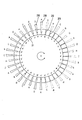
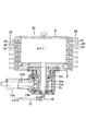
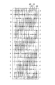
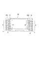
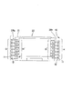
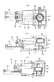
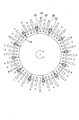
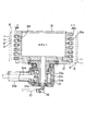
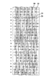
以下に本発明の実施形態を図面に基づいて説明する。図1は本発明の一実施形態を示すキャリア洗浄装置の回転ブラシの横断平面図、図2は同回転ブラシの縦断側面図、図3は同回転ブラシにおける毛束配置及びノズル配置を示すブラシ外周面の展開図、図4〜図6は同配置を示す回転ブラシの縦断面図、図7は同キャリア洗浄装置の全体構造及び動作を示す平面図及び側面図である。 Embodiments of the present invention will be described below with reference to the drawings. FIG. 1 is a transverse plan view of a rotating brush of a carrier cleaning apparatus showing an embodiment of the present invention, FIG. 2 is a longitudinal side view of the rotating brush, and FIG. 3 is a brush outer periphery showing a hair bundle arrangement and nozzle arrangement in the rotating brush. FIG. 4 to FIG. 6 are longitudinal sectional views of rotating brushes showing the same arrangement, and FIG. 7 are a plan view and a side view showing the overall structure and operation of the carrier cleaning apparatus.
本実施形態のキャリア洗浄装置は、図7に示すように、FOUPと呼ばれる300mmウエーハ用キャリア10(以下単にキャリア10と称す)の内面を回転ブラシ20によりブラシ洗浄するものである。キャリア10は、図3〜図5に示すように、所定枚数の300mmウエーハを水平姿勢で垂直方向に並列支持するために、内面に所定段の溝部11を有しており、それらの溝部11に水平に挿入されたウエーハを、下方の山部12で支持する構造になっている。
As shown in FIG. 7, the carrier cleaning apparatus of this embodiment is for cleaning the inner surface of a 300
ここで、溝部11の配列ピッチPは10mm、山部12の幅は約3mm、溝部11の幅は約7mmであることは前述したとおりである。
Here, as described above, the arrangement pitch P of the grooves 11 is 10 mm, the width of the
回転ブラシ20は、図1及び図2に示すように、回転中心線を垂直方向に向け、キャリア10内に挿入可能なドラム状の回転体21を有している。回転体21は有底筒状であり、且つ先端側(開口側)が端板21′により閉塞された密閉タイプである。この回転体21は、基端側(閉塞側)がL字状に組み合わされた支持部材22a,22 bの先に回転自在に取付けられており、支持部材22a,22 bの交差部内でかさ歯車23a,23bを用いてL字状に組み合わされた駆動軸24a,24bにより回転駆動される。
As shown in FIGS. 1 and 2, the rotating
即ち、水平な円筒状の支持部材22aの先端部に垂直な円筒状の支持部材22bがL字状に連結されている。駆動軸24a,24bは、支持部材22a,22 bの各内部に軸受により回転自在に支持されている。支持部材22a内の水平な駆動軸24aは、支持部材22b内の垂直な駆動軸24bと、かさ歯車23a,23bにより連結されている。支持部材22b内の垂直な駆動軸24bは、中心部に垂直な通液孔25を有すると共に、先端部にフランジ部を有しており、そのフランジ部が回転体21の基端側(閉塞側)の端板部にボルト及びシールにより水密に接続されている。
That is, a
通液孔25の先端部は、回転体21の端板部の中心に設けられた貫通孔を介して回転体21の内部に連通している。通液孔25の基端部は、回転シールによりシールされると共に、支持部材22bの基端部に装着されたL状のカップリング26と連通しており、該カップリング26を介して、支持部材22aに平行な給液管27と接続されている。これにより、洗浄液が水平な給液管27から垂直な駆動軸24bの貫通孔25を通って回転体21の内部に供給される。
The tip of the
回転体21の外周面には、毛束を回転体21の軸方向に並べて構成された6種類の毛束列A〜D及びG,Hが周方向に繰り返し配列されており、毛束列G及びHは、毛束列AとBの間及びCとDの間に位置している。また、これらの毛束列と共に、液吐出ノズルを回転体21の軸方向に並べて構成された6種類のノズル列A′〜D′及びG′,H′が周方向に繰り返し配列されており、ノズル列G′及びH′は、ノズル列A′とB′の間及びC′とD′の間に位置している。また、後で詳しく説明するが、毛束列A,G,B,C,H,Dのところにノズル列C′,H′,D′,A′,G′,B′が位置している。
On the outer peripheral surface of the
6種類の毛束列のうち、毛束列A〜Dは、図4〜図6に示すように、キャリア10の溝部11をブラッシングする溝部用の長い毛束28a〜28dにより構成されている。一方、毛束列G,Hは、山部12をブラッシングする山部用の短い毛束28g,28hにより構成されている。
Among the six types of hair bundle rows, the hair bundle rows A to D are constituted by
図7に示すように、回転ブラシ20の外径は、毛束列A〜Dの部分では、キャリア10の両側の側板部に設けられた溝部11,11の間隔より若干大きく設定されており、毛束列G,Hの部分では、両側の側板部に設けられた山部12,12の間隔より若干大きく設定されている。また、回転ブラシ20の回転軸方向の長さは、キャリア10の上下の端板間の距離(溝部11及び山部12の配列方向の内寸法)の約半分に設定されている。
As shown in FIG. 7, the outer diameter of the rotating
これにより、回転ブラシ20は、開口部が横を向き且つ溝部11及び山部12が垂直方向に並ぶ方向に寝かせて支持されたキャリア10内の約1/2の部分(上半分又は下半分)に、回転しながら溝部11及び山部12に沿って挿入されることにより、半数の溝部11及び山部12を両側で同時にブラッシングし、合わせて底面側でもブラッシングを行なう。そして、2回目の挿入で残りの約1/2の部分(下半分又は上半分)をブラッシングする。
As a result, the
毛束列A,Dを構成する毛束28a,28dは、前述したとおり溝部用の長い毛束であり、より具体的には半数の溝部11のうちの奇数番目(又は偶数番目)を担当する。 The hair bundles 28a and 28d constituting the hair bundle rows A and D are long hair bundles for the groove portions as described above, and more specifically, the odd-numbered (or even-numbered) half of the groove portions 11 are in charge. .
ここで、溝部11の幅は約7mmであり、毛束28a,28dの先端径は、溝部11に確実に挿入されるように、挿入可能な最大径(約10mm)よりも十分に小さい約6〜7mmに設定されている。また付け根部の径は、先端部の若干の広がりを考慮しても、この先端径が確保されるように、200mmウエーハキャリア用のブラシとほぼ同じ4.5〜5mmに設定されている。そして、毛束28a,28dは、対応する溝部11の幅方向で相反する方向、即ち一側面側及び他側面側に、溝部からはみ出す危険のない範囲内でできるたけ大きく変位して配置されている。
Here, the width of the groove 11 is about 7 mm, and the tip diameters of the
毛束列B,Cを構成する毛束28b,毛束28cも、毛束28a,28dと同様、溝部用の長い毛束である。毛束28a,28dと相違するのは、毛束28a,28dが半数の溝部11のうちの奇数番目(又は偶数番目)を担当するのに対し、毛束28b,28cは半数の溝部11のうちの偶数番目(又は奇数番目)を担当する点である。
Similarly to the
この相違点を除けば、毛束28b,28cは、毛束28a,28dと実質同一であり、それらの先端径は、溝部11に確実に挿入されるように、挿入可能な最大径(約10mm)よりも十分に小さい約6〜7mmに設定されている。また付け根部の径は、先端部の若干の広がりを考慮しても、この先端径が確保されるように、200mmウエーハキャリア用のブラシとほぼ同じ4〜5.5mmに設定されている。そして、毛束25b,25cも又、対応する溝部11の相反する側、即ち一側面側及び他側面側に、溝部からはみ出す危険のない範囲内で可及的に変位して配置されている。
Except for this difference, the
毛束列Gを構成する毛束28gは、前述したとおり山部用の短い毛束であり、半数の山部12のうちの奇数番目(又は偶数番目)を担当する。山部12の幅は、200mmウエーハキャリアとぼぼ同じ約3mmであるから、その先端径は、そのキャリア用のブラシとほぼ同じ約6〜7mmに設定されており、先端部の若干の広がりを考慮しても、この先端径が確保されるように、付け根部の径は約5mmに設定されている。
The
毛束列Hを構成する毛束28hも、毛束28gと同様、山部用の短い毛束である。毛束28gと相違するのは、半数の山部12のうちの偶数番目(又は奇数番目)を担当する点である。他は毛束28gと同様であり、その先端径は、200mmウエーハキャリア用のブラシとほぼ同じ約6〜7mmに設定されており、先端部の若干の広がりを考慮しても、この先端径が確保されるように、付け根部の径は約5mmに設定されている。
Similarly to the
なお、全ての毛束は、200mmウエーハキャリア用のブラシと同様に、ナイロンなどからなる0.2mm程度の樹脂細線を束ねて構成されており、回転体21の表面に形成された植設用の穴に嵌入固定されている。
In addition, all the hair bundles are configured by bundling about 0.2 mm of resin thin wires made of nylon or the like, like a brush for 200 mm wafer carrier, and are used for implantation formed on the surface of the
一方、6種類のノズル列A′〜D′及びG′,H′は、回転体21の回転軸方向に並ぶ複数の液吐出ノズル29a〜29d及び29g,29hにより、それぞれ構成されている。液吐出ノズル29a〜29d及び29g,29hは、いずれも回転体21の胴部を直角に貫通して回転体21の内部に連通する径方向の細孔である。
On the other hand, the six types of nozzle rows A ′ to D ′ and G ′ and H ′ are respectively constituted by a plurality of liquid discharge nozzles 29 a to 29 d and 29 g and 29 h arranged in the direction of the rotation axis of the
ここで、ノズル列A′〜D′及びG′,H′は、毛束列A〜D及びG,Hに各対応しており、より具体的には、ノズル列A′〜D′及びG′,H′を各構成する液吐出ノズル29a〜29d及び29g,29hは、毛束列A〜D及びG,Hを各構成する毛束28a〜28d及び28g,28hと、回転体21の回転軸方向において同じ位置に設けられている。
Here, the nozzle arrays A ′ to D ′ and G ′ and H ′ correspond to the hair bundle arrays A to D and G and H, respectively, more specifically, the nozzle arrays A ′ to D ′ and G. The liquid discharge nozzles 29a to 29d and 29g and 29h constituting 'and H' are respectively connected to the
即ち、ノズル列A′,D′を構成する液吐出ノズル29a,29dは、溝部11を担当し、より具体的には、回転ブラシ20をキャリア10内に挿入したときに、半数の溝部11のうちの奇数番目(又は偶数番目)に対向する。そして、液吐出ノズル29a,29dは、毛束28a,28dと同じように、対応する溝部11の幅方向で相反する方向、即ち一側面側及び他側面側に変位している。
That is, the liquid discharge nozzles 29 a and 29 d constituting the nozzle rows A ′ and D ′ are in charge of the groove 11, and more specifically, when the
ノズル列B′,C′を構成する液吐出ノズル29b,29cも、液吐出ノズル29a,29dと同様、溝部用である。液吐出ノズル29a,29dと相違するのは、液吐出ノズル29a,29dが半数の溝部11のうちの奇数番目(又は偶数番目)を担当するのに対し、液吐出ノズル29b,29cは半数の溝部11のうちの偶数番目(又は奇数番目)を担当する点である。 Similarly to the liquid discharge nozzles 29a and 29d, the liquid discharge nozzles 29b and 29c constituting the nozzle rows B ′ and C ′ are also for the groove portions. The liquid discharge nozzles 29a and 29d are different from the liquid discharge nozzles 29a and 29d in that the liquid discharge nozzles 29a and 29d are in charge of odd-numbered (or even-numbered) of the half of the groove portions 11, whereas the liquid discharge nozzles 29b and 29c are in half of the groove portions. 11 is an even number (or odd number) of 11 points.
この相違点を除けば、液吐出ノズル29b,29cは液吐出ノズル29a,29dと実質同一であり、対応する溝部11の相反する側、即ち一側面側及び他側面側に、毛束28b,28cと同じだけ変位している。
Except for this difference, the liquid discharge nozzles 29b and 29c are substantially the same as the liquid discharge nozzles 29a and 29d, and the
ノズル列G′,H′を構成する液吐出ノズル29g,29hは山部用であり、回転ブラシ20をキャリア10内に挿入したときに、山部12に対向する。そして、液吐出ノズル29gは、半数の山部12のうちの奇数番目(又は偶数番目)を担当し、液吐出ノズル29hは、半数の溝部11のうちの偶数番目(又は奇数番目)を担当する。
The liquid discharge nozzles 29g and 29h constituting the nozzle rows G ′ and H ′ are for the peak portion, and face the
このように構成された毛束列A〜D及びG,H、並びにノズル列A′〜D′及びG′,H′は、回転ブラシ20の回転方向及び回転軸方向において、次のように配置されている。
The hair bundle rows A to D and G, H and the nozzle rows A ′ to D ′ and G ′, H ′ configured as described above are arranged as follows in the rotation direction and the rotation axis direction of the
毛束列Aにおける毛束28a,28a・・の各間(中間点)にノズル列C′における液吐出ノズル29c,29c・・が配置されている。毛束列Bにおける毛束28b,28b・・の各間(中間点)にノズル列D′における液吐出ノズル29d,29d・・が配置されている。毛束列Cにおける毛束28c,28c・・の各間(中間点)にノズル列A′における液吐出ノズル29a,29a・・が配置されている。毛束列Dにおける毛束28d,28d・・の各間(中間点)にノズル列B′における液吐出ノズル29b,29b・・が配置されている。毛束列Gにおける毛束28g,28g・・の各間(中間点)にノズル列H′における液吐出ノズル29h,29h・・が配置されている。毛束列Hにおける毛束28h,28h・・の各間(中間点)にノズル列G′における液吐出ノズル29g,29g・・が配置されている。
The liquid discharge nozzles 29c, 29c,... In the nozzle row C 'are arranged between the
この配列によれば、回転体21の回転軸方向において隣接する毛束の間に液吐出ノズルが設けられているため、回転体21の回転方向及び回転軸方向において毛束及び液吐出ノズルを高密度に設けることができる。
According to this arrangement, since the liquid discharge nozzles are provided between the hair bundles adjacent in the rotation axis direction of the
しかも、奇数番目(又は偶数番目)の溝部用のノズル列A′,D′のところに偶数番目(又は奇数番目)の溝部用の毛束列B,Cが配置されており、且つ、その回転方向の両側に山部用の毛束列G,Hがそれぞれ配置され、その更に両側に奇数番目(又は偶数番目)の溝部用の毛束列A,Dが配置されている。偶数番目(又は奇数番目)の溝部用のノズル列B′,C′についても同様である。つまり、奇数番目(又は偶数番目)の溝部用のノズル列A′,D′の近傍に、偶数番目(又は奇数番目)の溝部用の毛束列B,C及び山部用の毛束列G,Hが配置されており、偶数番目(又は奇数番目)の溝部用のノズル列B′,C′の近傍には、奇数番目(又は偶数番目)の溝部用の毛束列A,D及び山部用の毛束列G,Hが配置されている。 Moreover, the even-numbered (or odd-numbered) groove portion bristles B, C are arranged at the odd-numbered (or even-numbered) groove-row nozzle rows A ′, D ′, and the rotation thereof. The hair bundle rows G and H for peak portions are arranged on both sides in the direction, and the hair bundle rows A and D for odd-numbered (or even-numbered) groove portions are arranged on both sides thereof. The same applies to the nozzle rows B ′ and C ′ for even-numbered (or odd-numbered) groove portions. That is, in the vicinity of the nozzle rows A ′ and D ′ for the odd-numbered (or even-numbered) groove portions, the hair-row rows B and C for the even-numbered (or odd-numbered) groove portions and the hair bundle rows G for the peak portions. , H are arranged, and in the vicinity of the nozzle rows B ′, C ′ for the even-numbered (or odd-numbered) groove portions, the hair bundle rows A, D and the peaks for the odd-numbered (or even-numbered) groove portions. The partial hair bundle rows G and H are arranged.
これにより、溝部をブラッシングする前にその溝部に洗浄液が供給され、溝部内面から汚れが浮き上がると共に、その溝部内面が効果的に保護されるだけでなく、溝部用の液吐出ノズルから噴出される洗浄液が、各対応する溝部用の毛束に遮られて勢いが弱まる事態が可及的に回避され、シャワーによる高い洗浄効果も維持される。 As a result, the cleaning liquid is supplied to the groove before brushing the groove, so that the dirt rises from the inner surface of the groove and the inner surface of the groove is not only effectively protected, but also the cleaning liquid ejected from the liquid discharge nozzle for the groove. However, the situation where the momentum is weakened by being blocked by the corresponding hair bundles for the grooves is avoided as much as possible, and the high cleaning effect by the shower is maintained.
最後に、本実施形態のキャリア洗浄装置の全体構造を図7により簡単に説明する。 Finally, the overall structure of the carrier cleaning apparatus of this embodiment will be briefly described with reference to FIG.
本実施形態のキャリア洗浄装置は、キャリア10を収容する洗浄槽30と、洗浄槽30内で回転ブラシ20を移動させる駆動機構40とを備えている。洗浄槽30は、キャリア収容部31とブラシ退避部32とに分かれており、キャリア収容部31内にクランプ33,33により、キャリア10を開口部がブラシ退避部32の側を向き溝部及び山部が垂直方向に並ぶ姿勢で固定する。キャリア収容部31の上面は、キャリア10を出し入れするためのハッチ34になっている。
The carrier cleaning device of this embodiment includes a
駆動機構40は、回転ブラシ20を支持する水平な支持部材41と、支持部材41を回転させる回転駆動部42と、支持部材41を回転駆動部42と共に直進移動させる直進駆動部43とを有している。支持部材41は、回転ブラシ20の水平な支持部材22aに対して偏心しており、その回転に伴う回転ブラシ20の反転動作により、回転ブラシ20をブラシ退避部32内でキャリア10内の上半分に対応するレベルと下半分に対応するレベルとに移動させる。直進駆動部43は、回転ブラシ20をキャリア収容部31とブラシ退避部32との間で往復移動させる。
The
次に、本実施形態のキャリア洗浄装置の機能について説明する。 Next, the function of the carrier cleaning apparatus of this embodiment will be described.
開口部が横を向き、溝部11及び山部12が垂直方向に並ぶようにキャリア10を洗浄槽内で固定する。そのキャリア10の内部、特に溝部11及び山部12の配列方向の1/2部分(上半分又は下半分)に、回転ブラシ20を回転軸が垂直方向を向く姿勢で、回転させながら溝部11及び山部12に沿って挿入する。
The
このとき、回転ブラシ20の回転体21内に洗浄液を供給する。回転体21内に供給された洗浄液は、ノズル列A′〜D′及びG′,H′を各構成する液吐出ノズル29a〜29d及び29g,29hから回転体21の外周側へ吐出される。
At this time, the cleaning liquid is supplied into the rotating
液吐出ノズル29a,29dから吐出された洗浄液は、半数の溝部11のうちの奇数番目(又は偶数番目)のものに供給され、液吐出ノズル29b,29cから吐出された洗浄液は、半数の溝部11のうちの偶数番目(又は奇数番目)のものに供給される。また、液吐出ノズル29gから吐出された洗浄液は、半数の山部12のうちの奇数番目(又は偶数番目)のものに供給され、液吐出ノズル29hから吐出された洗浄液は、半数の山部12のうちの偶数番目(又は奇数番目)のものに供給される。
The cleaning liquid discharged from the liquid discharge nozzles 29a and 29d is supplied to the odd-numbered (or even-numbered) one of the half groove portions 11, and the cleaning liquid discharged from the liquid discharge nozzles 29b and 29c is half the groove portion 11. Are supplied to even (or odd) ones. The cleaning liquid discharged from the liquid discharge nozzle 29g is supplied to the odd-numbered (or even-numbered) one of the
これにより、半数の溝部11のうちの奇数番目(又は偶数番目)のものが、表面に洗浄液を供給されながら、毛束列A,Dにおける毛束28a,28dによりブラッシングされる。同様に、半数の溝部11のうちの偶数番目(又は奇数番目)のものが、表面に洗浄液を供給されながら、毛束列B,Cにおける毛束28b,28cによりブラッシングされる。また、半数の山部12のうちの奇数番目(又は偶数番目)のものが、表面に洗浄液を供給されながら、毛束列Gにおける毛束28gによりブラッシングされ、偶数番目(又は奇数番目)のものが、表面に洗浄液を供給されながら、毛束列Hにおける毛束28hによりブラッシングされる。
Thereby, the odd-numbered (or even-numbered) ones of the half groove portions 11 are brushed by the
このように、本実施形態のキャリア洗浄装置では、キャリア10の溝部11及び山部12の各表面が専用の毛束より強力にブラッシングされる。しかも、毛束と干渉しないように設けられた専用の液吐出ノズルから十分な量の洗浄液が各表面に供給され、毛束との間に切れ目のない液膜を形成することにより、各表面が効果的に保護される。
Thus, in the carrier cleaning apparatus of this embodiment, each surface of the groove part 11 and the
また、毛束28a,28dは、溝部11に十分に挿入される得る先端径に設計されている。しかも、溝部11からはみ出しが生じない範囲内で相反する方向、即ち一側面側及び他側面側にそれぞれ変位している。更に、それぞれの先端径の合計は、ここでは12〜14mmと、溝部11の幅(約7mm)より十分に大きい。このため、十分なオーバーラップ量を確保でき、且つ毛束28a,28dを構成する樹脂細線の溝幅方向における合計本数として、個々の溝部11のブラッシングに十分な量を確保できる。
Further, the
これらのため、奇数番目(又は偶数番目)の溝部11が、毛束列A,Dにより、底面のみらず両側面を含め十分にブラッシングされ、しかも溝部11からの毛束の部分的なはみ出しが生じない。 For these reasons, the odd-numbered (or even-numbered) groove portions 11 are sufficiently brushed by the hair bundle arrays A and D, including not only the bottom surface but also both side surfaces, and the hair bundles partially protrude from the groove portions 11. Does not occur.
偶数番目(又は奇数番目)の溝部11についても、両側面側へ変位し且つオーバーラップした毛束列B,Cにおける毛束28b,28cにより、底面のみらず両側面を含め十分にブラッシングされ、しかも溝部11からの毛束の部分的なはみ出しが生じない。
Even the even-numbered (or odd-numbered) groove portions 11 are sufficiently brushed including not only the bottom surface but also both side surfaces by the
こうして、キャリア10の内部、特に溝部11及び山部12の配列方向の半分(上半分又は下半分)がブラッシングされると、回転ブラシ20をキャリア10の内部から一旦抜き出し、水平な支持部材41の中心回りに180度反転させた後、回転ブラシ20を再びキャリア10内の残り半分(下半分又は上半分)に挿入し、この部分の溝部11及び山部12をブラッシングする。
Thus, when the inside of the
かくして、キャリア10内の全ての溝部11及び山部12が、十分な量の洗浄液により保護されつつ、確実かつ十分にブラッシングされる。しかも、溝部11からの毛束の部分的なはみ出しが生じないため、はみ出しによる樹脂細線の変形及びこれによる回転ブラシ20の寿命短縮が回避される。
Thus, all the grooves 11 and the
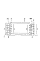
図8は本発明の別の実施形態を示すキャリア洗浄装置の回転ブラシの横断平面図、図9は同回転ブラシの縦断側面図、図10は同回転ブラシにおける毛束配置及びノズル配置を示すブラシ外周面の展開図である。 FIG. 8 is a cross-sectional plan view of a rotating brush of a carrier cleaning apparatus showing another embodiment of the present invention, FIG. 9 is a longitudinal side view of the rotating brush, and FIG. 10 is a brush showing a hair bundle arrangement and nozzle arrangement in the rotating brush. It is an expanded view of an outer peripheral surface.
本実施形態のキャリア洗浄装置では、回転ブラシ20の回転体21の表面に液吐出ノズル29として高打力ノズルを装着した点が、前述のキャリア洗浄装置と相違している。他の構成は、前述のキャリア洗浄装置と実質的に同一であり、同一部分に同一の符号を付して説明を省略する。
The carrier cleaning apparatus of this embodiment is different from the above-described carrier cleaning apparatus in that a high impact nozzle is mounted on the surface of the
詳しく説明すると、本実施形態のキャリア洗浄装置では、回転体21の表面に溝部用のブラシ列A〜Dが回転体21の回転方向に等間隔で繰り返し配列されている。回転体21の回転方向に対して、ブラシ列A,B,C,D,Aの各間には、山部用のブラシ列G、ノズル列E、山部用のブラシ列H、ノズル列Fがそれぞれ配置されている。
More specifically, in the carrier cleaning device of this embodiment, the brush rows A to D for groove portions are repeatedly arranged on the surface of the
ここで、ノズル列Eは、回転体21の回転軸方向に並ぶ複数の高打力ノズル29e、より詳しくは奇数番目(又は偶数番目)の溝部11を担当する高打力ノズル29eにより構成されており、ノズル列Fは、回転体21の回転軸方向に並ぶ複数の高打力ノズル29f、より詳しくは偶数番目(又は奇数番目)の溝部11を担当する高打力ノズル29fにより構成されている。
Here, the nozzle row E is composed of a plurality of high
高打力ノズルとは吐出圧を高めたノズルであり、前述のキャリア洗浄装置における溝部用の液吐出ノズル29a〜29dと異なり、対応する溝部11の幅方向中央部に対向し、両側へ変位しない配置になっている。 The high impact nozzle is a nozzle with a high discharge pressure, and unlike the groove liquid discharge nozzles 29a to 29d in the carrier cleaning device described above, it faces the center in the width direction of the corresponding groove 11 and does not displace to both sides. It is arranged.
本実施形態のキャリア洗浄装置では、溝部用の液吐出ノズル29として高打力ノズル29e,29fを用いている。そして、特定のノズル列、例えば奇数番目(又は偶数番目)の溝部用のノズル列Eに注目した場合、その回転方向両側に偶数番目(又は奇数番目)の溝部用の毛束列B,Cがそれぞれ位置し、その更に両側に山部用の毛束列G,Hがそれぞれ位置し、その更に両側に、前記ノズル列Eに対応する奇数番目(又は偶数番目)の溝部用の毛束列A,Dがそれぞれ位置している。偶数番目(又は奇数番目)の溝部用のノズル列Fについても同様である。
In the carrier cleaning apparatus of this embodiment,
つまり、本実施形態のキャリア洗浄装置でも、奇数番目(又は偶数番目)の溝部用のノズル列A′,D′の近傍に、偶数番目(又は奇数番目)の溝部用の毛束列B,C及び山部用の毛束列G,Hが配置されており、偶数番目(又は奇数番目)の溝部用のノズル列B′,C′の近傍には、奇数番目(又は偶数番目)の溝部用の毛束列A,D及び山部用の毛束列G,Hが配置されている。 That is, even in the carrier cleaning device of the present embodiment, the hair bundle rows B, C for even-numbered (or odd-numbered) groove portions are arranged in the vicinity of the nozzle rows A ′, D ′ for odd-numbered (or even-numbered) groove portions. And the hair bundle rows G and H for peak portions are arranged near the nozzle rows B 'and C' for even-numbered (or odd-numbered) groove portions, for odd-numbered (or even-numbered) groove portions. The hair bundle rows A and D and the hair bundle rows G and H for peak portions are arranged.
これにより、溝部11の表面はブラッシング前の段階で十分な量の洗浄液が供給され、損傷が効果的に防止されると同時に、高打力により浮き上がった汚れがブラッシングによって効率よくキャリア表面から取り除かれる。しかも、溝部用の液吐出ノズルが各対応する溝部用の毛束から一番遠い位置に設けられることになり、溝部用の液吐出ノズルから噴出された洗浄液が、キャリア内面に到達する前に各対応する溝部用の毛束に遮られて勢いが弱まり、シャワーによる洗浄効果が低下する事態が効果的に回避される。 As a result, a sufficient amount of cleaning liquid is supplied to the surface of the groove 11 in the stage before brushing, and damage is effectively prevented. At the same time, dirt floating due to high striking force is efficiently removed from the carrier surface by brushing. . In addition, the groove liquid discharge nozzles are provided at the furthest positions from the corresponding groove hair bundles, and the cleaning liquid ejected from the groove liquid discharge nozzles reaches the carrier inner surface before reaching the inner surface of the carrier. A situation in which the hair is blocked by the corresponding hair bundle for the groove and the momentum is weakened and the cleaning effect by the shower is reduced is effectively avoided.
なお、山部用の液吐出ノズル29は省略されているが、溝部用の液吐出ノズル29が高打力ノズル29e,29fであるため、山部12にも十分な量の洗浄液を供給でき、その省略による支障は生じない。
Although the
10 キャリア
11 溝部
12 山部
20 回転ブラシ
21 回転体
22 支持部材
23 かさ歯車
24 駆動軸
25 通液孔
26 カップリング
27 給液管
28a〜28d 溝部用の毛束
28g,28h 山部用の毛束
29a〜29f 溝部用の液吐出ノズル
29g,29h 山部用の液吐出ノズル
30 洗浄槽
40 駆動機構
DESCRIPTION OF
Claims (6)
Priority Applications (1)
| Application Number | Priority Date | Filing Date | Title |
|---|---|---|---|
| JP2004106765A JP2005294491A (en) | 2004-03-31 | 2004-03-31 | Carrier cleaning device |
Applications Claiming Priority (1)
| Application Number | Priority Date | Filing Date | Title |
|---|---|---|---|
| JP2004106765A JP2005294491A (en) | 2004-03-31 | 2004-03-31 | Carrier cleaning device |
Publications (1)
| Publication Number | Publication Date |
|---|---|
| JP2005294491A true JP2005294491A (en) | 2005-10-20 |
Family
ID=35327092
Family Applications (1)
| Application Number | Title | Priority Date | Filing Date |
|---|---|---|---|
| JP2004106765A Pending JP2005294491A (en) | 2004-03-31 | 2004-03-31 | Carrier cleaning device |
Country Status (1)
| Country | Link |
|---|---|
| JP (1) | JP2005294491A (en) |
Cited By (1)
| Publication number | Priority date | Publication date | Assignee | Title |
|---|---|---|---|---|
| CN106944394A (en) * | 2017-03-27 | 2017-07-14 | 贵州大学 | A kind of silicon wafer turnover flusher |
-
2004
- 2004-03-31 JP JP2004106765A patent/JP2005294491A/en active Pending
Cited By (1)
| Publication number | Priority date | Publication date | Assignee | Title |
|---|---|---|---|---|
| CN106944394A (en) * | 2017-03-27 | 2017-07-14 | 贵州大学 | A kind of silicon wafer turnover flusher |
Similar Documents
| Publication | Publication Date | Title |
|---|---|---|
| CN1165971C (en) | Washing method and device | |
| US5976267A (en) | Method and apparatus for mechanically cleaning the edges of wafers | |
| KR102194652B1 (en) | High stiffness, anti-slip scrubber brush assembly, high-stiffness mandrel, subassemblies, and assembly methods | |
| TW202038363A (en) | Substrate cleaning device | |
| KR101189611B1 (en) | Chuck for fixing wafer | |
| CN105873474B (en) | Toothbrush head for electric toothbrush | |
| US5138734A (en) | Motor-operated toothbrush bristle fastening structure | |
| JP7195617B2 (en) | toothbrush | |
| CN113057545A (en) | Brush disc | |
| JP4722869B2 (en) | Flat panel cleaning equipment | |
| KR101156051B1 (en) | Electric brush | |
| JP4864955B2 (en) | Chemical supply device | |
| KR102570224B1 (en) | Substrate procesing apparatus | |
| KR100840973B1 (en) | Flat Panel Cleaning Device | |
| US7841035B2 (en) | Disc cleaning machinery, disc cleaning device thereof and rotary brush thereof | |
| KR102622807B1 (en) | Cleaning member, substrate cleaning apparatus, and substrate processing apparatus | |
| CN118904848A (en) | Method for cleaning storage container for semiconductor and cleaning cavity | |
| JPH06151398A (en) | Wafer cleaning device | |
| JP2008173533A (en) | Parts cleaning jig | |
| JP2005260074A (en) | Carrier cleaning brush | |
| CN221983439U (en) | Cleaning structure convenient for cleaning inner wall of cupping jar | |
| JP2000173971A (en) | Carrier cleaning device | |
| CN112515538A (en) | Cleaning equipment for cleaning gaps of mahjong pillow mat | |
| JP3987948B2 (en) | Endoscopic ultrasonic cleaning device | |
| CN222568541U (en) | Wet cleaning brush head and wet cleaning equipment |