JP2005294427A - Reactor - Google Patents
Reactor Download PDFInfo
- Publication number
- JP2005294427A JP2005294427A JP2004105461A JP2004105461A JP2005294427A JP 2005294427 A JP2005294427 A JP 2005294427A JP 2004105461 A JP2004105461 A JP 2004105461A JP 2004105461 A JP2004105461 A JP 2004105461A JP 2005294427 A JP2005294427 A JP 2005294427A
- Authority
- JP
- Japan
- Prior art keywords
- spacer
- coil
- groove
- reactor
- shaped
- Prior art date
- Legal status (The legal status is an assumption and is not a legal conclusion. Google has not performed a legal analysis and makes no representation as to the accuracy of the status listed.)
- Pending
Links
- 125000006850 spacer group Chemical group 0.000 claims abstract description 62
- 238000004804 winding Methods 0.000 abstract description 7
- 230000015556 catabolic process Effects 0.000 abstract 1
- 238000005452 bending Methods 0.000 description 3
- 239000011248 coating agent Substances 0.000 description 3
- 238000000576 coating method Methods 0.000 description 3
- 238000009413 insulation Methods 0.000 description 3
- 239000004020 conductor Substances 0.000 description 2
- 238000004519 manufacturing process Methods 0.000 description 2
- 239000000463 material Substances 0.000 description 2
- 238000000034 method Methods 0.000 description 2
- 238000000465 moulding Methods 0.000 description 2
- 239000011347 resin Substances 0.000 description 2
- 229920005989 resin Polymers 0.000 description 2
- RNFJDJUURJAICM-UHFFFAOYSA-N 2,2,4,4,6,6-hexaphenoxy-1,3,5-triaza-2$l^{5},4$l^{5},6$l^{5}-triphosphacyclohexa-1,3,5-triene Chemical compound N=1P(OC=2C=CC=CC=2)(OC=2C=CC=CC=2)=NP(OC=2C=CC=CC=2)(OC=2C=CC=CC=2)=NP=1(OC=1C=CC=CC=1)OC1=CC=CC=C1 RNFJDJUURJAICM-UHFFFAOYSA-N 0.000 description 1
- 229920000784 Nomex Polymers 0.000 description 1
- 239000000919 ceramic Substances 0.000 description 1
- 239000003063 flame retardant Substances 0.000 description 1
- 239000002184 metal Substances 0.000 description 1
- 239000004763 nomex Substances 0.000 description 1
Images


Landscapes
- Coils Of Transformers For General Uses (AREA)
Abstract
Description
本発明は、エッジワイズ巻き構造のリアクトルに関する。 The present invention relates to a reactor having an edgewise winding structure.
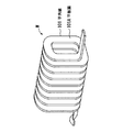
平角線は導体の部分を帯状にして形成されている。この平角線をコイルに用いる場合、帯状の平角線の導体表面に絶縁被膜が形成され、図7に示すように、平角線101の平板面101Aが互いに向かい合うように、かつ、互いに等しい間隔となるように、平角線101が巻かれる。こうした巻き方がエッジワイズ巻きである(特許文献1)。コイルに平角線101を用いると、平角線101の断面積が大きく、巻線抵抗が少ないので、大電流を流すことができるが、平角線101を巻く際に、コイルのコーナ部分Mが小径で曲げられると、コーナ部分Mの絶縁被膜が割れたり剥離したりして、コイルの絶縁が劣化し、コイルの耐圧が低下してしまう場合がある。
The flat wire is formed by stripping the conductor portion. When this rectangular wire is used for a coil, an insulating coating is formed on the conductor surface of the strip-shaped rectangular wire, and as shown in FIG. 7, the
そこで従来は、コイルの耐圧を保つために、このコイルの互いに隣接する平板面101Aの間隔を離していた。コイルの間隔を確保するために、断面が櫛歯状のスペーサをコイルの各間隔に入れ、大電流で高耐圧のコイルを実現していた。
上述した、平角線101を用いたコイルには、次の課題がある。コイルの耐圧を保つために、このコイルでは、スペーサを用いる。しかし、このスペーサはコイルの長さに応じて作られているために、コイルの全長が異なる場合に、このコイルに応じた別のスペーサを作る必要があるという課題があり、コイルに応じて各種のスペーサを用意することになるので、コイルのリアクトルの製造コストを上げる結果となる。
The coil using the
本発明は、前記の課題を解決し、エッジワイズ巻き構造の全長の異なるコイルに対して、耐圧に必要なコイルの間隔を1つのスペーサで確保することを可能にするリアクトルを提供することにある。 An object of the present invention is to provide a reactor that solves the above-described problems and makes it possible to secure a coil interval necessary for pressure resistance with a single spacer for coils having different lengths in an edgewise winding structure. .
前記課題を解決するために、請求項1の発明は、平角線の平板面部分が互いに向かい合うように巻かれたコイルと、前記コイルの少なくとも1つのコイル面から、このコイル面の各隙間に挿入される、櫛歯形状をしたスペーサとを有し、前記スペーサの櫛歯形状の凹部の底部分に、このスペーサの幅方向に沿って溝が設けられ、前記スペーサが前記コイルのコイル面の各隙間に挿入される際に、前記コイルの長さに応じて、前記スペーサの溝に沿ってこのスペーサが切断されていることを特徴とするリアクトルである。
請求項2の発明は、請求項1に記載のリアクトルにおいて、前記スペーサの溝の断面形状がV字状であることを特徴とする。
In order to solve the above-mentioned problems, the invention of claim 1 is characterized in that a coil wound so that flat plate surface portions of a rectangular wire face each other and at least one coil surface of the coil are inserted into each gap of the coil surface. A comb-shaped spacer, and a groove is provided in the bottom portion of the comb-shaped recess of the spacer along the width direction of the spacer. The reactor is characterized in that when inserted into the gap, the spacer is cut along the groove of the spacer according to the length of the coil.
According to a second aspect of the present invention, in the reactor according to the first aspect, the cross-sectional shape of the groove of the spacer is V-shaped.
請求項1の発明により、スペーサに切断用の溝を設けたので、全長の異なるコイルに対して、耐圧に必要なコイルの間隔を1つのスペーサで確保することができる。この結果、複数のスペーサを用意する必要がないので、リアクトルの製造コストを低減することができる。
請求項2の発明により、溝をV字状にしたので、折り曲げ等による切断を容易にすることができる。
According to the first aspect of the present invention, since the groove for cutting is provided in the spacer, it is possible to secure the coil interval necessary for the pressure resistance with one spacer for the coils having different lengths. As a result, since it is not necessary to prepare a plurality of spacers, the manufacturing cost of the reactor can be reduced.
According to the second aspect of the present invention, since the groove is V-shaped, cutting by bending or the like can be facilitated.
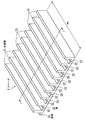
本実施形態によるリアクトルを図1に示す。このリアクトルは、コア1と、コイル2と、スペーサ3とで構成されている。断面形状が長方形のコア1は、ロ字状に形成されている。各コイル2は、平角線21をエッジワイズ巻(図7)にしたものである。先に説明したように、平角線21を巻く際に、コイル2のコーナ部分Mが小径で曲げられると、コーナ部分Mの絶縁被膜が割れたり剥離したりして、コイル2の絶縁が劣化し、コイル2の耐圧が低下してしまう場合がある。そこで、本実施形態では、コイル2の平板面部分22を所定間隔にして、耐圧低下を防ぐために、スペーサ3を用いている。つまり、コイル2のコイル面2Aの隙間を所定間隔に広げている。
A reactor according to this embodiment is shown in FIG. The reactor includes a core 1, a
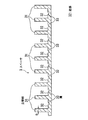
スペーサ3は、図2および図3に示すように、樹脂の成型によって作られ、断面形状が櫛歯状である。つまり、スペーサ3では、細長板状の複数の立壁部31が等間隔で配列され、この間隔はコイル2を形成する平角線21が挿入可能な距離である。立壁部31の厚さDは、コイル2の耐圧を確保するための前記の所定間隔である。各立壁部31の端部は、細長板状の各底部32によって保持されている。つまり、隣接する立壁部31の間に底部32が挿入された形状となっている。本実施形態では、底部32の中央に、かつ、底部32の長手方向(スペーサ3の幅方向)に沿って、V字状の溝33が設けられている。なお、図1では、図面の都合上、溝33の記載を省略している。溝33は、スペーサ3を切断するために用いられる。溝33によるスペーサ3の切断には、折り曲げなどの各種の方法がある。
As shown in FIGS. 2 and 3, the
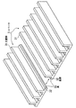
スペーサ3の代わりとして、例えば図4に示すものがある。図4のスペーサ3Aでは、2つのV字状の溝33A、33Bが互いに向かい合うように、底部32に設けられている。2つの溝33A、33Bをスペーサ3Aに設けることにより、折り曲げなどの際に、切断をさらに容易にすることができる。
As an alternative to the
スペーサ3の幅W1は、コイル面2Aの幅W2に比べて狭く、また、後述する図6では、コイル面2Aの幅W2とほぼ同じである。つまり、スペーサ3の幅W1には自由度がある。
The width W1 of the
本実施形態によるリアクトルは、前記の構成である。本実施形態では、スペーサ3としてコイル2より長いものをあらかじめ用意しておき、コイル2の長さに応じて、スペーサ3を切断し、スペーサ3の長さLを調整する。このとき、図5に示すように、スペーサ3の溝33によって、極めて容易にスペーサ3を切断することができる。さらに、本実施形態によるリアクトルによれば、スペーサ3の切断により、スペーサ3の長さ調整が可能であるので、従来のように、コイル2の長さに応じたスペーサを用意する必要がなく、1つのスペーサ3で全長の異なるコイル2に対応可能である。
The reactor according to the present embodiment has the above-described configuration. In the present embodiment, a
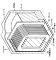
ところで、図1のリアクトルとは別に、例えば図6に示すリアクトルがある。図6は、このリアクトルの四分の一の分割部分を示す斜視図である。このリアクトルは、コア1と、コイル2と、スペーサ3と、ボビン4と、ケース5とで構成されている。コア1、コイル2、およびスペーサ3は、図1と寸法が異なるが、図1と同一または同一と見なされるので、これらの説明を省略する。ボビン2にはコア1が挿入され、ボビン4のフランジ41間にはコイル2が挿入されている。さらに、これらのコア1、コイル2、スペーサ3、およびボビン4は金属製のケース5に収納されている。
By the way, there exists a reactor shown, for example in FIG. 6 apart from the reactor of FIG. FIG. 6 is a perspective view showing a quartered portion of the reactor. This reactor includes a core 1, a
本実施形態によるリアクトルは、前記の構成である。本実施形態では、図1と同様に、スペーサ3としてコイル2より長いものをあらかじめ用意しておき、コイル2の長さに応じて、スペーサ3を切断し、コイル2とケース5との間に、かつ、コイル2の各隙間に差し込む。こうした図6のリアクトルによっても、切断によるスペーサ3の長さ調整が可能であるので、従来のように、コイル2の長さに応じたスペーサ3を用意する必要がなく、1つのスペーサ3で全長の異なるコイル2に対応可能である。
The reactor according to the present embodiment has the above-described configuration. In the present embodiment, as in FIG. 1, a
以上、本発明の実施形態を詳述してきたが、具体的な構成は本実施形態に限られるものではなく、本発明の要旨を逸脱しない範囲の設計の変更等があっても、本発明に含まれる。たとえば、本実施形態では、底部32の中央に溝33、33A、33Bを設けたが、溝33、33A、33Bを設ける位置は底部32に対して任意である。また、溝33、33A、33Bの断面形状がV字であったが、U字等の他の形状でもよい。さらに、スペーサ3、3Aとして樹脂を用いたが、例えばノーメックス等の難燃性材やセラミックスを成型加工したものを用いてもよい。
Although the embodiment of the present invention has been described in detail above, the specific configuration is not limited to this embodiment, and even if there is a design change or the like without departing from the gist of the present invention, the present invention is not limited thereto. included. For example, in the present embodiment, the
1 コア
2 コイル
2A コイル面
21 平角線
22 平板面部分
3、3A スペーサ
31 立壁部
32 底部
33、33A、33B 溝
4 ボビン
41 フランジ
5 ケース
DESCRIPTION OF SYMBOLS 1
Claims (2)
前記コイル(2)の少なくとも1つのコイル面(2A)から、このコイル面(2A)の各隙間に挿入される、櫛歯形状をしたスペーサ(3)とを有し、
前記スペーサ(3)の櫛歯形状の凹部の底部分に、このスペーサ(3)の幅方向に沿って溝(33)が設けられ、前記スペーサ(3)が前記コイル(2)のコイル面(2A)の各隙間に挿入される際に、前記コイル(2)の長さに応じて、前記スペーサ(3)の溝(33)に沿ってこのスペーサ(3)が切断されていることを特徴とするリアクトル。 A coil (2) wound so that flat plate portions of a flat wire face each other;
A comb-shaped spacer (3) inserted into each gap of the coil surface (2A) from at least one coil surface (2A) of the coil (2);
A groove (33) is provided along the width direction of the spacer (3) in the bottom portion of the comb-shaped recess of the spacer (3), and the spacer (3) is a coil surface of the coil (2) ( 2A), the spacer (3) is cut along the groove (33) of the spacer (3) according to the length of the coil (2) when inserted into each gap of 2A). Reactor.
Priority Applications (1)
| Application Number | Priority Date | Filing Date | Title |
|---|---|---|---|
| JP2004105461A JP2005294427A (en) | 2004-03-31 | 2004-03-31 | Reactor |
Applications Claiming Priority (1)
| Application Number | Priority Date | Filing Date | Title |
|---|---|---|---|
| JP2004105461A JP2005294427A (en) | 2004-03-31 | 2004-03-31 | Reactor |
Publications (1)
| Publication Number | Publication Date |
|---|---|
| JP2005294427A true JP2005294427A (en) | 2005-10-20 |
Family
ID=35327043
Family Applications (1)
| Application Number | Title | Priority Date | Filing Date |
|---|---|---|---|
| JP2004105461A Pending JP2005294427A (en) | 2004-03-31 | 2004-03-31 | Reactor |
Country Status (1)
| Country | Link |
|---|---|
| JP (1) | JP2005294427A (en) |
Cited By (12)
| Publication number | Priority date | Publication date | Assignee | Title |
|---|---|---|---|---|
| JP2008147345A (en) * | 2006-12-08 | 2008-06-26 | Denso Corp | Method of manufacturing reactor |
| US7786833B2 (en) * | 2005-07-28 | 2010-08-31 | Suncall Corporation | Edgewise coil |
| JP2012191139A (en) * | 2011-03-14 | 2012-10-04 | Tamura Seisakusho Co Ltd | Coil device |
| JP2013042021A (en) * | 2011-08-18 | 2013-02-28 | Nagano Japan Radio Co | Coil component and method of manufacturing the same |
| JP2014138045A (en) * | 2013-01-16 | 2014-07-28 | Hitachi Metals Ltd | Common mode choke |
| WO2015099100A1 (en) * | 2013-12-26 | 2015-07-02 | 株式会社オートネットワーク技術研究所 | Reactor |
| JP2015126143A (en) * | 2013-12-26 | 2015-07-06 | 株式会社オートネットワーク技術研究所 | Reactor |
| JP2015126146A (en) * | 2013-12-26 | 2015-07-06 | 株式会社オートネットワーク技術研究所 | Reactor |
| JP2015216145A (en) * | 2014-05-07 | 2015-12-03 | 株式会社オートネットワーク技術研究所 | Reactor |
| JP2021197441A (en) * | 2020-06-15 | 2021-12-27 | 長野日本無線株式会社 | Insulation spacer for coil and coil component |
| JP2023178885A (en) * | 2022-06-06 | 2023-12-18 | 長野日本無線株式会社 | coil parts |
| WO2025047578A1 (en) * | 2023-08-30 | 2025-03-06 | 株式会社オートネットワーク技術研究所 | Reactor, converter, and power conversion device |
-
2004
- 2004-03-31 JP JP2004105461A patent/JP2005294427A/en active Pending
Cited By (14)
| Publication number | Priority date | Publication date | Assignee | Title |
|---|---|---|---|---|
| US7786833B2 (en) * | 2005-07-28 | 2010-08-31 | Suncall Corporation | Edgewise coil |
| JP2008147345A (en) * | 2006-12-08 | 2008-06-26 | Denso Corp | Method of manufacturing reactor |
| JP2012191139A (en) * | 2011-03-14 | 2012-10-04 | Tamura Seisakusho Co Ltd | Coil device |
| JP2013042021A (en) * | 2011-08-18 | 2013-02-28 | Nagano Japan Radio Co | Coil component and method of manufacturing the same |
| JP2014138045A (en) * | 2013-01-16 | 2014-07-28 | Hitachi Metals Ltd | Common mode choke |
| JP2015126143A (en) * | 2013-12-26 | 2015-07-06 | 株式会社オートネットワーク技術研究所 | Reactor |
| WO2015099100A1 (en) * | 2013-12-26 | 2015-07-02 | 株式会社オートネットワーク技術研究所 | Reactor |
| JP2015126146A (en) * | 2013-12-26 | 2015-07-06 | 株式会社オートネットワーク技術研究所 | Reactor |
| JP2015216145A (en) * | 2014-05-07 | 2015-12-03 | 株式会社オートネットワーク技術研究所 | Reactor |
| JP2021197441A (en) * | 2020-06-15 | 2021-12-27 | 長野日本無線株式会社 | Insulation spacer for coil and coil component |
| JP7426906B2 (en) | 2020-06-15 | 2024-02-02 | 長野日本無線株式会社 | Insulating spacers and coil parts for coils |
| JP2023178885A (en) * | 2022-06-06 | 2023-12-18 | 長野日本無線株式会社 | coil parts |
| JP7807323B2 (en) | 2022-06-06 | 2026-01-27 | 長野日本無線株式会社 | Coil parts |
| WO2025047578A1 (en) * | 2023-08-30 | 2025-03-06 | 株式会社オートネットワーク技術研究所 | Reactor, converter, and power conversion device |
Similar Documents
| Publication | Publication Date | Title |
|---|---|---|
| JP2005294427A (en) | Reactor | |
| CN101657953B (en) | Insert prefabricated concentrated windings into stator slots | |
| CN102301567B (en) | motor armature | |
| US11336141B2 (en) | Insulator | |
| US20140184378A1 (en) | Slotted bobbin magnetic component devices and methods | |
| CN201048312Y (en) | Segmented stator for an electric machine | |
| US20230318386A1 (en) | Stator and wedge insertion device | |
| KR20090031838A (en) | Electrical winding conductor with rectangular cross section | |
| US9601255B2 (en) | Amorphous core transformer | |
| KR20170031074A (en) | Sheet metal part with improved connection tab geometry | |
| CN109767892B (en) | Choke coil | |
| JP2007531328A (en) | Low AC Resistance Foil Winding for Magnetic Coil on Gapped Core | |
| CN111834750B (en) | antenna | |
| WO2019219226A1 (en) | Transposed cable and winding comprising said transposed cable | |
| US5644181A (en) | Stator lamination design having a tapered opening | |
| US6433664B1 (en) | Coil | |
| CN101238630A (en) | Method for winding a motor and auxiliary winding former | |
| US20190139697A1 (en) | Magnetic element, metal annular winding and method for manufacturing the same | |
| JP2002313646A (en) | Wound type common mode choke coil | |
| EP4170825A1 (en) | Linearized magnet wire connector | |
| EP2806436B1 (en) | Electrical insulation system | |
| JP2005294335A (en) | Insulating structure of coil | |
| JP4598603B2 (en) | Wire, coil, stator coil, rotor coil, and transformer | |
| JP2008043020A (en) | Winding insulation structure | |
| JP2015035866A (en) | Segment coil and stator |
Legal Events
| Date | Code | Title | Description |
|---|---|---|---|
| A621 | Written request for application examination |
Effective date: 20070131 Free format text: JAPANESE INTERMEDIATE CODE: A621 |
|
| A977 | Report on retrieval |
Effective date: 20090727 Free format text: JAPANESE INTERMEDIATE CODE: A971007 |
|
| A131 | Notification of reasons for refusal |
Free format text: JAPANESE INTERMEDIATE CODE: A131 Effective date: 20090804 |
|
| A02 | Decision of refusal |
Free format text: JAPANESE INTERMEDIATE CODE: A02 Effective date: 20100105 |