JP2005294087A - Light source unit, illumination optical device, exposure apparatus, and exposure method - Google Patents
Light source unit, illumination optical device, exposure apparatus, and exposure method Download PDFInfo
- Publication number
- JP2005294087A JP2005294087A JP2004108674A JP2004108674A JP2005294087A JP 2005294087 A JP2005294087 A JP 2005294087A JP 2004108674 A JP2004108674 A JP 2004108674A JP 2004108674 A JP2004108674 A JP 2004108674A JP 2005294087 A JP2005294087 A JP 2005294087A
- Authority
- JP
- Japan
- Prior art keywords
- light
- light source
- source unit
- reflecting mirror
- euv
- Prior art date
- Legal status (The legal status is an assumption and is not a legal conclusion. Google has not performed a legal analysis and makes no representation as to the accuracy of the status listed.)
- Pending
Links
Images
Classifications
-
- G—PHYSICS
- G03—PHOTOGRAPHY; CINEMATOGRAPHY; ANALOGOUS TECHNIQUES USING WAVES OTHER THAN OPTICAL WAVES; ELECTROGRAPHY; HOLOGRAPHY
- G03F—PHOTOMECHANICAL PRODUCTION OF TEXTURED OR PATTERNED SURFACES, e.g. FOR PRINTING, FOR PROCESSING OF SEMICONDUCTOR DEVICES; MATERIALS THEREFOR; ORIGINALS THEREFOR; APPARATUS SPECIALLY ADAPTED THEREFOR
- G03F7/00—Photomechanical, e.g. photolithographic, production of textured or patterned surfaces, e.g. printing surfaces; Materials therefor, e.g. comprising photoresists; Apparatus specially adapted therefor
- G03F7/70—Microphotolithographic exposure; Apparatus therefor
- G03F7/708—Construction of apparatus, e.g. environment aspects, hygiene aspects or materials
- G03F7/7085—Detection arrangement, e.g. detectors of apparatus alignment possibly mounted on wafers, exposure dose, photo-cleaning flux, stray light, thermal load
-
- H—ELECTRICITY
- H05—ELECTRIC TECHNIQUES NOT OTHERWISE PROVIDED FOR
- H05G—X-RAY TECHNIQUE
- H05G2/00—Apparatus or processes specially adapted for producing X-rays, not involving X-ray tubes, e.g. involving generation of a plasma
- H05G2/001—Production of X-ray radiation generated from plasma
- H05G2/008—Production of X-ray radiation generated from plasma involving an energy-carrying beam in the process of plasma generation
- H05G2/0082—Production of X-ray radiation generated from plasma involving an energy-carrying beam in the process of plasma generation the energy-carrying beam being a laser beam
- H05G2/0086—Optical arrangements for conveying the laser beam to the plasma generation location
-
- B—PERFORMING OPERATIONS; TRANSPORTING
- B82—NANOTECHNOLOGY
- B82Y—SPECIFIC USES OR APPLICATIONS OF NANOSTRUCTURES; MEASUREMENT OR ANALYSIS OF NANOSTRUCTURES; MANUFACTURE OR TREATMENT OF NANOSTRUCTURES
- B82Y10/00—Nanotechnology for information processing, storage or transmission, e.g. quantum computing or single electron logic
-
- G—PHYSICS
- G03—PHOTOGRAPHY; CINEMATOGRAPHY; ANALOGOUS TECHNIQUES USING WAVES OTHER THAN OPTICAL WAVES; ELECTROGRAPHY; HOLOGRAPHY
- G03F—PHOTOMECHANICAL PRODUCTION OF TEXTURED OR PATTERNED SURFACES, e.g. FOR PRINTING, FOR PROCESSING OF SEMICONDUCTOR DEVICES; MATERIALS THEREFOR; ORIGINALS THEREFOR; APPARATUS SPECIALLY ADAPTED THEREFOR
- G03F7/00—Photomechanical, e.g. photolithographic, production of textured or patterned surfaces, e.g. printing surfaces; Materials therefor, e.g. comprising photoresists; Apparatus specially adapted therefor
- G03F7/70—Microphotolithographic exposure; Apparatus therefor
- G03F7/70008—Production of exposure light, i.e. light sources
- G03F7/70033—Production of exposure light, i.e. light sources by plasma extreme ultraviolet [EUV] sources
-
- G—PHYSICS
- G03—PHOTOGRAPHY; CINEMATOGRAPHY; ANALOGOUS TECHNIQUES USING WAVES OTHER THAN OPTICAL WAVES; ELECTROGRAPHY; HOLOGRAPHY
- G03F—PHOTOMECHANICAL PRODUCTION OF TEXTURED OR PATTERNED SURFACES, e.g. FOR PRINTING, FOR PROCESSING OF SEMICONDUCTOR DEVICES; MATERIALS THEREFOR; ORIGINALS THEREFOR; APPARATUS SPECIALLY ADAPTED THEREFOR
- G03F7/00—Photomechanical, e.g. photolithographic, production of textured or patterned surfaces, e.g. printing surfaces; Materials therefor, e.g. comprising photoresists; Apparatus specially adapted therefor
- G03F7/70—Microphotolithographic exposure; Apparatus therefor
- G03F7/70058—Mask illumination systems
- G03F7/70141—Illumination system adjustment, e.g. adjustments during exposure or alignment during assembly of illumination system
-
- H—ELECTRICITY
- H05—ELECTRIC TECHNIQUES NOT OTHERWISE PROVIDED FOR
- H05G—X-RAY TECHNIQUE
- H05G2/00—Apparatus or processes specially adapted for producing X-rays, not involving X-ray tubes, e.g. involving generation of a plasma
- H05G2/001—Production of X-ray radiation generated from plasma
- H05G2/002—Supply of the plasma generating material
- H05G2/0027—Arrangements for controlling the supply; Arrangements for measurements
-
- H—ELECTRICITY
- H05—ELECTRIC TECHNIQUES NOT OTHERWISE PROVIDED FOR
- H05G—X-RAY TECHNIQUE
- H05G2/00—Apparatus or processes specially adapted for producing X-rays, not involving X-ray tubes, e.g. involving generation of a plasma
- H05G2/001—Production of X-ray radiation generated from plasma
- H05G2/008—Production of X-ray radiation generated from plasma involving an energy-carrying beam in the process of plasma generation
- H05G2/0082—Production of X-ray radiation generated from plasma involving an energy-carrying beam in the process of plasma generation the energy-carrying beam being a laser beam
- H05G2/0084—Control of the laser beam
-
- H—ELECTRICITY
- H05—ELECTRIC TECHNIQUES NOT OTHERWISE PROVIDED FOR
- H05G—X-RAY TECHNIQUE
- H05G2/00—Apparatus or processes specially adapted for producing X-rays, not involving X-ray tubes, e.g. involving generation of a plasma
- H05G2/001—Production of X-ray radiation generated from plasma
- H05G2/009—Auxiliary arrangements not involved in the plasma generation
Landscapes
- Physics & Mathematics (AREA)
- Engineering & Computer Science (AREA)
- Optics & Photonics (AREA)
- Plasma & Fusion (AREA)
- General Physics & Mathematics (AREA)
- Chemical & Material Sciences (AREA)
- Nanotechnology (AREA)
- Crystallography & Structural Chemistry (AREA)
- Theoretical Computer Science (AREA)
- Mathematical Physics (AREA)
- Health & Medical Sciences (AREA)
- Environmental & Geological Engineering (AREA)
- Epidemiology (AREA)
- Public Health (AREA)
- Exposure Of Semiconductors, Excluding Electron Or Ion Beam Exposure (AREA)
- Exposure And Positioning Against Photoresist Photosensitive Materials (AREA)
- X-Ray Techniques (AREA)
Abstract
【課題】 所望の光強度角度分布(面内分布)を有するEUV光を安定的に供給することのできる光源ユニット。
【解決手段】 標的材料をプラズマ化し、生成されたプラズマ(P)からEUV光を輻射させる光源本体(11)と、光源本体から輻射されたEUV光を所定の方向に反射するための反射鏡(12)と、反射鏡に入射するEUV光の光強度の角度分布(面内分布)の軸対称性を検出するための検出系と、検出系の検出結果に基づいて光強度の角度分布(面内分布)がほぼ軸対称になるように光源本体を調整するための調整系とを備えている。
【選択図】 図3PROBLEM TO BE SOLVED: To provide a light source unit capable of stably supplying EUV light having a desired light intensity angle distribution (in-plane distribution).
A light source body (11) that radiates EUV light from a generated plasma (P) and a reflecting mirror for reflecting the EUV light emitted from the light source body in a predetermined direction. 12), a detection system for detecting the axial symmetry of the light intensity angular distribution (in-plane distribution) of the EUV light incident on the reflecting mirror, and the light intensity angular distribution (surface) based on the detection result of the detection system. And an adjustment system for adjusting the light source body so that the internal distribution is substantially axisymmetric.
[Selection] Figure 3
Description
本発明は、光源ユニット、照明光学装置、露光装置および露光方法に関する。さらに詳細には、本発明は、5〜50nm程度の波長を有するEUV光(極端紫外線)を用いて半導体素子などのマイクロデバイスをフォトリソグラフィ工程で製造するのに使用される露光装置に好適な光源ユニットに関するものである。 The present invention relates to a light source unit, an illumination optical apparatus, an exposure apparatus, and an exposure method. More specifically, the present invention is a light source suitable for an exposure apparatus used for manufacturing microdevices such as semiconductor elements in a photolithography process using EUV light (extreme ultraviolet rays) having a wavelength of about 5 to 50 nm. It is about the unit.
この種の露光装置では、転写すべき回路パターンの微細化に伴って解像力の一層の向上が要求されており、露光光としてより短波長の光を用いるようになっている。なお、本明細書における「光」とは、目で見える狭義の「光」だけではなく、電磁波のうち1mmよりも短い波長を有する、いわゆる赤外線からX線までを含む広義の「光」を意味する。近年、次世代装置として、5〜50nm程度の波長を有するEUV(Extreme UltraViolet)光を用いる露光装置(以下、「EUVL(Extreme UltraViolet Lithography:極紫外リソグラフィ)露光装置」という)が提案されている。 In this type of exposure apparatus, further improvement in resolving power is required as the circuit pattern to be transferred becomes finer, and light having a shorter wavelength is used as exposure light. In addition, “light” in this specification means not only “light” in a narrow sense that can be seen with eyes, but also “light” in a broad sense including a so-called infrared ray to X-ray having a wavelength shorter than 1 mm among electromagnetic waves. To do. In recent years, an exposure apparatus using EUV (Extreme UltraViolet) light having a wavelength of about 5 to 50 nm (hereinafter referred to as “EUVL (Extreme UltraViolet Lithography) exposure apparatus”) has been proposed as a next-generation apparatus.
現在、EUV光を供給する光源として、以下に示す3つのタイプの光源が提案されている。
(1)SR(シンクロトロン放射光)を供給する光源
(2)LPP(Laser Produced Plasma)光源
(3)DPP(Discharge Produced Plasma)光源。
Currently, the following three types of light sources have been proposed as light sources for supplying EUV light.
(1) Light source for supplying SR (synchrotron radiation) (2) LPP (Laser Produced Plasma) light source (3) DPP (Discharge Produced Plasma) light source
LPP光源(レーザプラズマ光源)では、ターゲット材料(標的材料)上にレーザ光を集光し、ターゲット材料をプラズマ化してEUV光を得る。一方、DPP光源(放電プラズマ光源)では、電極間にターゲット材料が存在する状態で電極間に電圧を印加すると、ある電圧を越えたところで電極間に放電が生じ、ターゲット材料がプラズマ化する。この放電によって電極間に大電流が流れ、この大電流によって生じる磁場によりプラズマ自身が微小空間内に圧縮され、プラズマ温度が上昇する。この高温プラズマからEUV光が放出(輻射)される。 In an LPP light source (laser plasma light source), laser light is condensed on a target material (target material), and the target material is turned into plasma to obtain EUV light. On the other hand, in a DPP light source (discharge plasma light source), when a voltage is applied between the electrodes in a state where the target material exists between the electrodes, a discharge occurs between the electrodes when the voltage exceeds a certain voltage, and the target material becomes plasma. Due to this discharge, a large current flows between the electrodes, and the plasma itself is compressed into a minute space by the magnetic field generated by the large current, and the plasma temperature rises. EUV light is emitted (radiated) from the high-temperature plasma.
DPP光源では、たとえば長時間に亘る運転に起因する電極の消耗により、プラズマ生成位置(すなわち発光位置)が経時的に変化することがある。また、LPP光源では、長時間に亘って運転すると、ターゲット材料を供給するノズルの近傍に生成されるプラズマからのイオンなどの影響によりノズルが変形したり消耗したりする。その結果、ノズルの変形や消耗によりターゲット材料の供給経路が経時的に変化し、ひいてはプラズマ生成位置が経時的に変化することがある。 In the DPP light source, the plasma generation position (that is, the light emission position) may change with time due to, for example, electrode consumption due to long-time operation. In addition, when the LPP light source is operated for a long time, the nozzle is deformed or consumed due to the influence of ions from plasma generated in the vicinity of the nozzle that supplies the target material. As a result, the supply path of the target material may change over time due to the deformation or consumption of the nozzle, and the plasma generation position may change over time.
あるいは、LPP光源では、レーザ光の集光位置が経時的に変化し、ひいてはプラズマ生成位置が経時的に変化することがある。DPP光源やLPP光源において、プラズマ生成位置が変化すると、プラズマから輻射されて反射鏡(集光ミラー)に入射するEUV光の光強度の角度分布(面内分布)が変化し、ひいては光源ユニットから供給されるEUV光の光強度の角度分布が変化してしまう。 Alternatively, in the LPP light source, the condensing position of the laser light may change with time, and eventually the plasma generation position may change with time. When the plasma generation position changes in a DPP light source or an LPP light source, the angular distribution (in-plane distribution) of the light intensity of EUV light that is radiated from the plasma and enters the reflecting mirror (condensing mirror) changes. The angular distribution of the light intensity of the supplied EUV light will change.
また、消耗した電極やノズルや反射鏡を交換する際に、新たな部品を元の位置に正確に取り付けることができず、交換取付け誤差が発生することがある。この場合、部品の交換前とは異なる位置にプラズマが生成されたり、反射鏡を介してEUV光の集光される位置すなわち集光位置が部品交換前の集光位置から位置ずれしたりする。このように、プラズマ生成位置や集光位置が変化すると、すなわち光源位置が変化すると、照明条件が変化することになり、露光装置に適用される場合には正確な露光を行うことができなくなる。 Further, when exchanging worn electrodes, nozzles, and reflecting mirrors, new parts cannot be accurately attached to their original positions, and replacement attachment errors may occur. In this case, plasma is generated at a position different from that before the replacement of the component, or the position where the EUV light is collected through the reflecting mirror, that is, the position where the EUV light is collected is shifted from the position of the concentration before the replacement of the component. As described above, when the plasma generation position or the condensing position is changed, that is, when the light source position is changed, the illumination condition is changed, and accurate exposure cannot be performed when applied to the exposure apparatus.
本発明は、前述の課題に鑑みてなされたものであり、所望の光強度角度分布(面内分布)を有するEUV光を安定的に供給することのできる光源ユニットを提供することを目的とする。また、本発明は、発光位置(プラズマ生成位置)や集光位置をほぼ所定位置に安定的に維持することのできる光源ユニットを提供することを目的とする。また、本発明は、所望の光強度角度分布(面内分布)を有するEUV光を安定的に供給する光源ユニットまたは発光位置や集光位置をほぼ所定位置に安定的に維持する光源ユニットを用いて、所望の照明条件のもとでマスクパターンを感光性基板上に忠実に転写することのできる露光装置および露光方法を提供することを目的とする。 The present invention has been made in view of the above-described problems, and an object thereof is to provide a light source unit capable of stably supplying EUV light having a desired light intensity angle distribution (in-plane distribution). . It is another object of the present invention to provide a light source unit that can stably maintain a light emission position (plasma generation position) and a light collection position at a predetermined position. Further, the present invention uses a light source unit that stably supplies EUV light having a desired light intensity angle distribution (in-plane distribution) or a light source unit that stably maintains a light emission position and a light collection position at a predetermined position. An object of the present invention is to provide an exposure apparatus and an exposure method capable of faithfully transferring a mask pattern onto a photosensitive substrate under desired illumination conditions.
前記課題を解決するために、本発明の第1形態では、標的材料をプラズマ化し、生成されたプラズマからEUV光を輻射させる光源本体と、
前記光源本体から輻射されたEUV光を所定の方向に反射するための反射鏡と、
前記反射鏡に入射するEUV光の光強度の角度分布(面内分布)の軸対称性を検出するための検出系と、
前記検出系の検出結果に基づいて、前記光強度の角度分布(面内分布)がほぼ軸対称になるように前記光源本体を調整するための調整系とを備えていることを特徴とする光源ユニットを提供する。
In order to solve the above-described problem, in the first embodiment of the present invention, a light source main body that converts a target material into plasma and emits EUV light from the generated plasma;
A reflecting mirror for reflecting the EUV light radiated from the light source body in a predetermined direction;
A detection system for detecting axial symmetry of the angular distribution (in-plane distribution) of the light intensity of EUV light incident on the reflecting mirror;
And an adjustment system for adjusting the light source body so that the angular distribution (in-plane distribution) of the light intensity is substantially axially symmetric based on the detection result of the detection system. Provide units.
第1形態の好ましい態様によれば、前記検出系は、前記反射鏡の周囲に配置された複数の光検出器を有する。この場合、前記検出系は、前記光源本体から前記反射鏡の周囲に達する光のうち所定波長のEUV光だけを反射して各光検出器へ導くための複数のミラーをさらに有することが好ましい。あるいは、前記検出系は、前記光源本体から前記反射鏡の周囲に達する光のうち所定波長のEUV光だけを透過させて各光検出器へ導くための複数の選択フィルタをさらに有することが好ましい。 According to a preferred aspect of the first aspect, the detection system has a plurality of photodetectors arranged around the reflecting mirror. In this case, it is preferable that the detection system further includes a plurality of mirrors for reflecting only EUV light having a predetermined wavelength out of the light reaching the periphery of the reflecting mirror from the light source body and guiding the light to each photodetector. Alternatively, it is preferable that the detection system further includes a plurality of selection filters for transmitting only EUV light having a predetermined wavelength out of light reaching the periphery of the reflecting mirror from the light source body and guiding the light to each photodetector.
第1形態の好ましい態様によれば、前記光源本体は、前記標的材料を供給するためのノズルと、該ノズルから供給される前記標的材料に対して集光するようにレーザ光を照射するためのレーザ照射系とを有し、前記調整系は、前記レーザ光の集光位置を変化させるための集光位置変化手段を有する。あるいは、前記光源本体は、前記標的材料を供給するためのノズルと、該ノズルから供給される前記標的材料に対して集光するようにレーザ光を照射するためのレーザ照射系とを有し、前記調整系は、前記ノズルの位置および姿勢を調整するためのノズル調整手段と、レーザ光の集光位置を変化させるための集光位置変化手段とを有することが好ましい。これらの場合、前記集光位置変化手段は、前記レーザ照射系の光路中に配置されて光軸に対して傾動可能な平行平面板を有することが好ましい。 According to a preferred aspect of the first aspect, the light source main body is configured to irradiate a laser beam so as to focus on the target material supplied from the nozzle and a nozzle for supplying the target material. A laser irradiation system, and the adjustment system includes a condensing position changing unit for changing a condensing position of the laser light. Alternatively, the light source body includes a nozzle for supplying the target material, and a laser irradiation system for irradiating a laser beam so as to focus the target material supplied from the nozzle, The adjustment system preferably includes nozzle adjusting means for adjusting the position and posture of the nozzle, and condensing position changing means for changing the condensing position of the laser beam. In these cases, it is preferable that the condensing position changing means has a parallel plane plate that is disposed in the optical path of the laser irradiation system and can be tilted with respect to the optical axis.
第1形態の好ましい態様によれば、前記光源本体は、放電により前記標的材料をプラズマ化するための一対の電極を有し、前記調整系は、放電に際して前記一対の電極を放電軸廻りに回転させるための電極駆動手段を有する。 According to a preferred aspect of the first aspect, the light source body has a pair of electrodes for converting the target material into plasma by discharge, and the adjustment system rotates the pair of electrodes around the discharge axis during discharge. There is an electrode driving means.
本発明の第2形態では、標的材料をプラズマ化し、生成されたプラズマからEUV光を輻射させる光源本体と、
前記光源本体から輻射されたEUV光を反射して所定位置に集光させるための反射鏡と、
前記所定位置を介したEUV光の光強度の角度分布(面内分布)の軸対称性を検出するための検出系と、
前記検出系の検出結果に基づいて、前記光強度の角度分布(面内分布)がほぼ軸対称になるように前記反射鏡の位置および姿勢を調整するための調整系とを備えていることを特徴とする光源ユニットを提供する。
In the second embodiment of the present invention, a light source body that converts the target material into plasma and emits EUV light from the generated plasma;
A reflecting mirror for reflecting EUV light radiated from the light source body and condensing it at a predetermined position;
A detection system for detecting the axial symmetry of the angular distribution (in-plane distribution) of the light intensity of the EUV light through the predetermined position;
And an adjustment system for adjusting the position and posture of the reflecting mirror so that the angular distribution (in-plane distribution) of the light intensity is substantially axially symmetric based on the detection result of the detection system. A light source unit is provided.
第2形態の好ましい態様によれば、前記検出系は、前記所定位置を介したEUV光の有効光束の周囲に配置された複数の光検出器を有する。この場合、前記検出系は、前記光源本体から前記有効光束の周囲に達する光のうち所定波長のEUV光だけを透過させて各光検出器へ導くための複数の選択フィルタをさらに有する。あるいは、前記検出系は、前記光源本体から前記有効光束の周囲に達する光のうち所定波長のEUV光だけを反射して各光検出器へ導くための複数のミラーをさらに有することが好ましい。 According to a preferred aspect of the second aspect, the detection system has a plurality of photodetectors arranged around the effective luminous flux of the EUV light through the predetermined position. In this case, the detection system further includes a plurality of selection filters for transmitting only the EUV light having a predetermined wavelength out of the light reaching the periphery of the effective light beam from the light source body and guiding the light to each photodetector. Alternatively, it is preferable that the detection system further includes a plurality of mirrors for reflecting only EUV light having a predetermined wavelength out of light reaching the periphery of the effective light beam from the light source body and guiding it to each photodetector.
第2形態の好ましい態様によれば、前記光源本体は、前記標的材料を供給するためのノズルと、該ノズルから供給される前記標的材料に対して集光するようにレーザ光を照射するためのレーザ照射系とを有し、前記調整系は、前記レーザ光の集光位置を変化させるための集光位置変化手段を有する。あるいは、前記光源本体は、前記標的材料を供給するためのノズルと、該ノズルから供給される前記標的材料に対して集光するようにレーザ光を照射するためのレーザ照射系とを有し、前記調整系は、前記ノズルの位置および姿勢を調整するためのノズル調整手段と、レーザ光の集光位置を変化させるための集光位置変化手段とを有することが好ましい。これらの場合、前記集光位置変化手段は、前記レーザ照射系の光路中に配置されて光軸に対して傾動可能な平行平面板を有することが好ましい。 According to a preferred aspect of the second aspect, the light source body is configured to irradiate a laser beam so as to focus on the target material supplied from the nozzle and a nozzle for supplying the target material. A laser irradiation system, and the adjustment system includes a condensing position changing unit for changing a condensing position of the laser light. Alternatively, the light source body includes a nozzle for supplying the target material, and a laser irradiation system for irradiating a laser beam so as to focus the target material supplied from the nozzle, The adjustment system preferably includes nozzle adjusting means for adjusting the position and posture of the nozzle, and condensing position changing means for changing the condensing position of the laser beam. In these cases, it is preferable that the condensing position changing means has a parallel plane plate that is disposed in the optical path of the laser irradiation system and can be tilted with respect to the optical axis.
第2形態の好ましい態様によれば、前記光源本体は、放電により前記標的材料をプラズマ化するための一対の電極を有し、前記調整系は、放電に際して前記一対の電極を放電軸廻りに回転させるための電極駆動手段を有する。 According to a preferred aspect of the second embodiment, the light source body has a pair of electrodes for converting the target material into plasma by discharge, and the adjustment system rotates the pair of electrodes around the discharge axis during discharge. There is an electrode driving means.
本発明の第3形態では、標的材料をプラズマ化し、生成されたプラズマからEUV光を輻射させる光源本体と、
前記光源本体から輻射されたEUV光を反射して集光させるための反射鏡と、
前記反射鏡で反射されたEUV光の集光位置を検出するための検出系と、
前記検出系の検出結果に基づいて、前記集光位置がほぼ所定位置になるように調整するための調整系とを備えていることを特徴とする光源ユニットを提供する。
In the third embodiment of the present invention, the target material is turned into plasma and EUV light is radiated from the generated plasma;
A reflecting mirror for reflecting and collecting EUV light radiated from the light source body;
A detection system for detecting a condensing position of EUV light reflected by the reflecting mirror;
There is provided a light source unit comprising: an adjustment system for adjusting the condensing position to be approximately a predetermined position based on a detection result of the detection system.
第3形態の好ましい態様によれば、前記検出系は、前記所定位置に配置された二次元光検出器を有する。また、前記調整系は、前記反射鏡の位置および姿勢を調整するための反射鏡調整手段を有することが好ましい。また、前記調整系は、前記プラズマからのEUV光の発光位置を変化させるための発光位置変化手段を有することが好ましい。 According to a preferred aspect of the third aspect, the detection system includes a two-dimensional photodetector arranged at the predetermined position. Moreover, it is preferable that the said adjustment system has a reflective mirror adjustment means for adjusting the position and attitude | position of the said reflective mirror. Moreover, it is preferable that the said adjustment system has a light emission position change means for changing the light emission position of the EUV light from the said plasma.
第3形態の好ましい態様によれば、前記光源本体は、前記標的材料を供給するためのノズルと、該ノズルから供給される前記標的材料に対して集光するようにレーザ光を照射するためのレーザ照射系とを有し、前記発光位置変化手段は、前記ノズルの位置および姿勢を調整するためのノズル調整手段と、レーザ光の集光位置を変化させるための集光位置変化手段とを有する。この場合、前記集光位置変化手段は、前記レーザ照射系の光路中に配置されて光軸に対して傾動可能な平行平面板を有することが好ましい。また、前記集光位置変化手段は、前記レーザ照射系の光路中に配置されて光軸に沿って移動可能なレンズを有することが好ましい。 According to a preferred aspect of the third aspect, the light source main body is configured to irradiate a laser beam so as to focus on the target material supplied from the nozzle and a nozzle for supplying the target material. A laser irradiation system, and the light emission position changing means includes a nozzle adjusting means for adjusting the position and posture of the nozzle, and a light collecting position changing means for changing the light collecting position of the laser light. . In this case, it is preferable that the condensing position changing means has a parallel plane plate that is disposed in the optical path of the laser irradiation system and can be tilted with respect to the optical axis. Moreover, it is preferable that the said condensing position change means has a lens which is arrange | positioned in the optical path of the said laser irradiation system, and can move along an optical axis.
第3形態の好ましい態様によれば、前記光源本体は、放電により前記標的材料をプラズマ化するための一対の電極を有し、前記発光位置変化手段は、前記一対の電極の位置を変化させるための電極位置変化手段を有する。 According to a preferred aspect of the third aspect, the light source body has a pair of electrodes for converting the target material into plasma by discharge, and the light emission position changing means changes the positions of the pair of electrodes. Electrode position changing means.
本発明の第4形態では、一対の電極間の放電により標的材料をプラズマ化し、生成されたプラズマからEUV光を輻射させる光源本体と、
前記光源本体から輻射されたEUV光を所定の方向に反射するための反射鏡と、
前記プラズマからのEUV光の発光位置を検出するための検出系と、
前記検出系の検出結果に基づいて、前記発光位置がほぼ所定位置になるように前記一対の電極の位置を調整するための調整系とを備えていることを特徴とする光源ユニットを提供する。
In the fourth aspect of the present invention, a light source body that converts plasma into a target material by discharge between a pair of electrodes and radiates EUV light from the generated plasma;
A reflecting mirror for reflecting the EUV light radiated from the light source body in a predetermined direction;
A detection system for detecting the emission position of EUV light from the plasma;
There is provided a light source unit comprising: an adjustment system for adjusting the positions of the pair of electrodes so that the light emission position becomes substantially a predetermined position based on a detection result of the detection system.
第4形態の好ましい態様によれば、前記検出系は、前記プラズマからの光をピンホールを介して検出するための複数の二次元光検出器を有する。 According to a preferred aspect of the fourth aspect, the detection system includes a plurality of two-dimensional photodetectors for detecting light from the plasma through pinholes.
本発明の第5形態では、第1形態〜第4形態の光源ユニットと、該光源ユニットからのEUV光を被照射面へ導くための導光光学系とを備えていることを特徴とする照明光学装置を提供する。 According to a fifth aspect of the present invention, the illumination includes the light source unit of the first to fourth aspects and a light guide optical system for guiding the EUV light from the light source unit to the irradiated surface. An optical device is provided.
本発明の第6形態では、標的材料をプラズマ化し、生成されたプラズマからEUV光を輻射させる光源本体と、
前記光源本体から輻射されたEUV光を反射して集光させるための反射鏡と、
前記反射鏡で一旦集光されたEUV光をほぼ平行光に変換するためのコリメータミラーと、
前記コリメータミラーと被照射面との間に配置されたオプティカルインテグレータと、
前記オプティカルインテグレータに入射するEUV光の光強度の角度分布(面内分布)の軸対称性を検出するための検出系と、
前記検出系の検出結果に基づいて、前記光強度の角度分布(面内分布)がほぼ軸対称になるように調整するための調整系とを備えていることを特徴とする照明光学装置を提供する。
In a sixth aspect of the present invention, a light source body that converts a target material into plasma and emits EUV light from the generated plasma;
A reflecting mirror for reflecting and collecting EUV light radiated from the light source body;
A collimator mirror for converting EUV light once condensed by the reflecting mirror into substantially parallel light;
An optical integrator disposed between the collimator mirror and the irradiated surface;
A detection system for detecting the axial symmetry of the angular distribution (in-plane distribution) of the light intensity of EUV light incident on the optical integrator;
An illumination optical device comprising: an adjustment system for adjusting the angular distribution (in-plane distribution) of the light intensity to be substantially axially symmetric based on a detection result of the detection system. To do.
第6形態の好ましい態様によれば、前記オプティカルインテグレータは、前記コリメータミラー側から順に、第1フライアイミラーと第2フライアイミラーとを有し、前記検出系は、前記EUV光の入射を受けて前記第1フライアイミラーの要素ミラーから放出される光電子電流を検出するための電流計を有する。また、前記調整系は、前記反射鏡の位置および姿勢を調整するための反射鏡調整手段を有することが好ましい。また、前記調整系は、前記コリメータミラーの位置および姿勢を調整するためのミラー調整手段を有することが好ましい。 According to a preferred aspect of the sixth aspect, the optical integrator has a first fly-eye mirror and a second fly-eye mirror in order from the collimator mirror side, and the detection system receives the incidence of the EUV light. And an ammeter for detecting the photoelectron current emitted from the element mirror of the first fly-eye mirror. Moreover, it is preferable that the said adjustment system has a reflective mirror adjustment means for adjusting the position and attitude | position of the said reflective mirror. Moreover, it is preferable that the said adjustment system has a mirror adjustment means for adjusting the position and attitude | position of the said collimator mirror.
本発明の第7形態では、所定のパターンが形成された反射型のマスクを照明するための第5形態または第6形態の照明光学装置と、前記マスクのパターン像を感光性基板上に形成するための投影光学系とを備えていることを特徴とする露光装置を提供する。この場合、前記投影光学系に対して前記マスクおよび前記感光性基板を所定方向に沿って相対移動させて前記マスクのパターンを前記感光性基板上へ投影露光することが好ましい。 In the seventh embodiment of the present invention, the illumination optical device of the fifth or sixth embodiment for illuminating a reflective mask on which a predetermined pattern is formed, and a pattern image of the mask are formed on a photosensitive substrate. An exposure apparatus is provided that includes a projection optical system. In this case, it is preferable that the mask and the photosensitive substrate are moved relative to the projection optical system along a predetermined direction to project and expose the mask pattern onto the photosensitive substrate.
本発明の第8形態では、第5形態または第6形態の照明光学装置を用いて所定のパターンが形成された反射型のマスクを照明する照明工程と、投影光学系を介して前記マスクのパターンを前記感光性基板上へ投影露光する露光工程とを含むことを特徴とする露光方法を提供する。この場合、前記露光工程では、前記投影光学系に対して前記マスクおよび感光性基板を所定方向に沿って相対移動させて前記マスクのパターンを前記感光性基板上へ投影露光することが好ましい。 In an eighth aspect of the present invention, an illumination step of illuminating a reflective mask on which a predetermined pattern is formed using the illumination optical device of the fifth or sixth aspect, and the pattern of the mask via a projection optical system And an exposure step of projecting exposure onto the photosensitive substrate. In this case, in the exposure step, it is preferable that the mask and the photosensitive substrate are relatively moved along a predetermined direction with respect to the projection optical system to project and expose the mask pattern onto the photosensitive substrate.
本発明では、反射鏡に入射するEUV光や反射鏡により一旦集光して発散するEUV光の光強度の角度分布(面内分布)が様々な原因により実質的に軸非対称になることがあっても、光強度の角度分布がほぼ軸対称になるように調整することができる。また、本発明では、反射鏡で反射されたEUV光の集光位置やプラズマからのEUV光の発光位置が様々な原因により変化することがあっても、集光位置や発光位置が所定位置になるように調整することができる。 In the present invention, the angular distribution (in-plane distribution) of the EUV light incident on the reflecting mirror and the EUV light once condensed by the reflecting mirror and diverged may become substantially axially asymmetric due to various causes. However, the angle distribution of the light intensity can be adjusted so as to be substantially axially symmetric. Further, in the present invention, even if the condensing position of the EUV light reflected by the reflecting mirror or the light emitting position of the EUV light from the plasma may change due to various causes, the condensing position or the light emitting position is set to a predetermined position. Can be adjusted.
すなわち、本発明の光源ユニットでは、所望の光強度角度分布(面内分布)を有するEUV光を安定的に供給したり、発光位置(プラズマ生成位置)や集光位置をほぼ所定位置に安定的に維持したりすることができる。したがって、本発明の露光装置および露光方法では、所望の光強度角度分布(面内分布)を有するEUV光を安定的に供給する光源ユニットまたは発光位置や集光位置をほぼ所定位置に安定的に維持する光源ユニットを用いて、所望の照明条件のもとでマスクパターンを感光性基板上に忠実に転写することができ、ひいては高精度なマイクロデバイスを高スループットで製造することができる。 That is, in the light source unit of the present invention, EUV light having a desired light intensity angle distribution (in-plane distribution) can be stably supplied, and the light emission position (plasma generation position) and the light collection position can be stably set to a predetermined position. Or can be maintained. Therefore, in the exposure apparatus and exposure method of the present invention, the light source unit that stably supplies EUV light having a desired light intensity angle distribution (in-plane distribution) or the light emission position and the light collection position can be stably set to a predetermined position. By using the light source unit to be maintained, the mask pattern can be faithfully transferred onto the photosensitive substrate under a desired illumination condition, and as a result, a high-precision microdevice can be manufactured with high throughput.
本発明の実施形態を、添付図面に基づいて説明する。
図1は、本発明の実施形態にかかる光源ユニットを備えた露光装置の全体構成を概略的に示す図である。また、図2は、ウェハ上に形成される静止露光領域と光軸との位置関係を示す図である。図1において、投影光学系の光軸方向すなわち感光性基板であるウェハWの法線方向に沿ってZ軸を、ウェハWの面内において図1の紙面に平行な方向にY軸を、ウェハWの面内において図1の紙面に垂直な方向にX軸をそれぞれ設定している。
Embodiments of the present invention will be described with reference to the accompanying drawings.
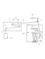
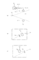
FIG. 1 is a view schematically showing an overall configuration of an exposure apparatus including a light source unit according to an embodiment of the present invention. FIG. 2 is a diagram showing the positional relationship between the still exposure region formed on the wafer and the optical axis. In FIG. 1, the Z axis along the optical axis direction of the projection optical system, that is, the normal direction of the wafer W which is a photosensitive substrate, the Y axis in the direction parallel to the paper surface of FIG. In the plane of W, the X axis is set in a direction perpendicular to the paper surface of FIG.
図1を参照すると、本実施形態の露光装置は、露光光を供給するためのDPP光源タイプの光源ユニット1またはLPP光源タイプの光源ユニット2を備えている。光源ユニット1または2から供給された露光光、例えば13.5nm(または11.5nm)の波長を有するEUV光(X線)Lは、照明光学系3および平面反射鏡4を介して、転写すべきパターンが形成された反射型のマスク(レチクル)Mを照明する。マスクMは、そのパターン面がXY平面に沿って延びるように、Y方向に沿って移動可能なマスクステージ5によって保持されている。
Referring to FIG. 1, the exposure apparatus of this embodiment includes a DPP light source type
マスクステージ5の移動は、レーザ干渉計6により計測されるように構成されている。照明されたマスクMのパターンからの光は、反射型の投影光学系PLを介して、感光性基板であるウェハW上にマスクパターンの像を形成する。すなわち、ウェハW上には、図2に示すように、たとえばY軸に関して対称でX方向に沿って細長く延びる円弧状の露光領域(すなわち静止露光領域または実効露光領域)ERが形成される。
The movement of the mask stage 5 is configured to be measured by a
図2を参照すると、光軸AXを中心とした円形状の領域(イメージサークル)IF内において、このイメージサークルIFに接するように円弧状の静止露光領域ERが設定されている。ウェハWは、その露光面がXY平面に沿って延びるように、X方向およびY方向に沿って二次元的に移動可能なウェハステージ7によって保持されている。ウェハステージ7の移動は、マスクステージ5と同様に、レーザ干渉計8により計測されるように構成されている。
Referring to FIG. 2, in a circular area (image circle) IF centered on the optical axis AX, an arc-shaped still exposure area ER is set so as to be in contact with the image circle IF. The wafer W is held by a
こうして、マスクステージ5およびウェハステージ7をY方向に沿って移動させながら、すなわち投影光学系PLに対してマスクMおよびウェハWをY方向に沿って相対移動させながらスキャン露光(走査露光)を行うことにより、ウェハWの1つのショット領域にマスクMのパターンが転写される。また、ウェハステージ7をX方向およびY方向に沿って二次元的に移動させながら走査露光を繰り返すことにより、ウェハWの各ショット領域にマスクMのパターンが逐次転写される。
Thus, the scanning exposure (scanning exposure) is performed while moving the mask stage 5 and the
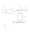
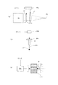
図3は、DPP光源タイプの光源ユニットの内部構成を概略的に示す図である。図3を参照すると、DPP光源タイプの光源ユニット1は、光源本体11と、凹面反射鏡12と、光源本体11および凹面反射鏡12を収容するチャンバ13とを備えている。光源本体11は、チャンバ13の隔壁13aに設けられた一対の電極11aおよび11bと、間隔を隔てた一対の電極11aと11bとの間にパルス高電圧を印加するための電力供給源11cとを有する。
FIG. 3 is a diagram schematically showing an internal configuration of a DPP light source type light source unit. Referring to FIG. 3, the DPP light source type
光源本体11では、例えば円筒状の形態を有する第1電極11aと、この第1電極11aを包囲する同心円筒状の形態を有する第2電極11bとの間に、図示を省略したガス供給源からキセノン(Xe)ガス11dが供給される。ターゲットガス(標的材料)としてのキセノンガス11dが供給された状態で第1電極11aと第2電極11bとの間に電力供給源11cからのパルス高電圧が印加されると、第1電極11aと第2電極11bとの間に放電が起こる。この放電によりキセノンガス11dがイオン化してプラズマが生成され、生成されたプラズマが電磁力により収斂されて高温で高密度のプラズマPとなり、このプラズマPからEUV光が輻射される。なお、ターゲットとして、たとえばスズ(Sn)等を用いることもできる。
In the
凹面反射鏡12は、凹面形状(球面形状、非球面形状、回転楕円面形状など)の反射面12aを有し、チャンバ13の隔壁13aに取り付けられている。凹面反射鏡12は、例えばニッケル(Ni),アルミニウム(Al),銅(Cu),シリコン(Si)のような加工性が高く且つ熱伝導率の高い金属で形成された反射鏡本体12b上に、反射面として例えばMo/Si製の多層膜12aをコートすることにより形成されている。
The concave reflecting
多層膜12aは、波長が13.5nmのEUV光を選択的に反射するとともに光学面の劣化および変形を防ぐ特性を有する。凹面反射鏡12の裏面側には、光源本体11からの輻射熱を受けて温度が上昇し易い凹面反射鏡12を冷却するための冷却機構14が取り付けられている。冷却機構14では、たとえば循環する冷媒(水、オイル、ガスなど)の作用により、凹面反射鏡12の反射面12aから熱伝導率の高い反射鏡本体12bを介して伝わった熱が効率良く外部へ排出される。
The
光源本体11から輻射されたEUV光は、凹面反射鏡12により一対の電極(11a,11b)側に向かって反射され、チャンバ13の隔壁13aに形成された開口部15の所定位置P1に集光する。一旦集光したEUV光は、開口部15を介してチャンバ13の外部へ導かれ、開口部15の近傍に配置された選択フィルタ16に入射する。選択フィルタ16は、ジルコニウム(Zr)、シリコン(Si)、または窒化シリコン(SiN)などにより形成された薄膜であって、光源本体11からの可視光および紫外光を遮るとともに13.5nmの所望波長のEUV光を選択的に透過させる特性を有する。
The EUV light radiated from the
チャンバ13には、真空ポンプのような真空排気装置17が接続されている。この真空排気装置17の作用により、チャンバ13の内部にはほぼ真空雰囲気が形成されている。同様に、EUV光の減衰を抑えるために、光源ユニット1から照明光学系3および投影光学系PLを経てウェハWに至るまでのすべての光路中においてほぼ真空雰囲気が形成されている。なお、真空雰囲気に限定されることなく、適当な不活性ガスで満たされた減圧雰囲気をすべての光路中において形成することもできる。一対の電極(11a,11b)の間に供給されたターゲットガス11dは、プラズマPが生成された後に真空排気装置17の作用によりチャンバ13の外部へ排出される。
A
チャンバ13の隔壁13aに形成された比較的小さな開口部15は、チャンバ13内の光源ユニット1側の低い真空度と後段の照明光学系3側の高い真空度とを分離する差動排気に利用される。この差動排気により、光源ユニット1側の真空度が低くても、開口部15よりも下流側の真空度が良好に保たれる。開口部15による差動排気が不十分な場合には、開口部15の近傍に選択フィルタ16を配置して差動排気に利用することが有効である。ただし、開口部15による差動排気が十分な場合や、光源本体11から開口部15に達する可視光および紫外光が無視できる程度であれば、選択フィルタ16の設置を省略することもできる。
The relatively
本実施形態のDPP光源タイプSの光源ユニット1では、キセノンガス11dが供給された状態で第1電極11aと第2電極11bとの間に電力供給源11cからのパルス高電圧が印加される。その結果、一対の電極11aと11bとの間の放電により生成されたプラズマPからEUV光が輻射される。プラズマPから輻射されたEUV光は凹面反射鏡12に入射し、その多層膜反射面12aにより一対の電極(11a,11b)側に向かって反射される。凹面反射鏡12の多層膜反射面12aにより選択的に反射された所望波長(13.5nm)のEUV光は開口部15の所定位置P1に一旦集光し、選択フィルタ16を介してさらに波長選択された後、EUV光Lとして照明光学系3に入射する。
In the
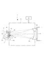
図4は、LPP光源タイプの光源ユニットの内部構成を概略的に示す図である。図4を参照すると、LPP光源タイプの光源ユニット2は、真空容器(チャンバ)21と、真空容器21に接続された真空ポンプ(真空排気装置)22と、真空容器21の内部の所定位置に配置されたガスジェットノズル23と、真空容器21の隔壁に取り付けられた凹面反射鏡24とを備えている。
FIG. 4 is a diagram schematically showing an internal configuration of an LPP light source type light source unit. Referring to FIG. 4, the
真空容器21の内部は、真空ポンプ22の作用により排気され、後述のプラズマPから輻射されたEUV光が減衰しないようにほぼ真空状態に設定されている。同様に、EUV光の減衰を抑えるために、光源ユニット2から照明光学系3および投影光学系PLを経てウェハWに至るまでのすべての光路中がほぼ真空状態に設定されている。なお、真空雰囲気に限定されることなく、適当な不活性ガスで満たされた減圧雰囲気をすべての光路中において形成することもできる。
The inside of the
ガスジェットノズル23は、例えばステンレス鋼により形成され、キセノン(Xe)ガスのようなターゲットガスが充填されたガスボンベ(不図示)に接続されている。ガスボンベ内のターゲットガスは、配管およびバルブなどを介して、ガスジェットノズル23から真空容器21の内部に噴射される。ガスジェットノズル23から所定経路に沿って噴射されたターゲットガス23aは、プラズマPを生成する際の標的材料となる。なお、ターゲットとして、たとえばスズ(Sn)等を用いることもできる。
The
凹面反射鏡24は、例えば回転楕円面形状の反射面24aを有し、真空容器21の隔壁に取り付けられている。凹面反射鏡24は、その第1焦点位置がプラズマPを生成すべき所定位置とほぼ一致するように位置決めされ、反射面24aは真空容器21の内部に位置し、裏面(反射面24aと反対側の面)は真空容器21の外部の大気側に露出している。凹面反射鏡24は、例えば低熱膨張ガラス(ゼロデュアーやULE等)により形成された反射鏡本体24b上に、反射面として例えばMo/Si製の多層膜24aをコートすることにより形成されている。
The concave reflecting
ただし、反射面としての多層膜24aは、凹面反射鏡24の表面の中央透過領域24cを除く領域に形成されている。多層膜24aは、波長が13.5nmのEUV光を選択的に反射するとともに光学面の劣化および変形を防ぐ特性を有する。具体的には、例えば多層膜の最上層にルテニウム(Ru)をコートし、有機汚染や酸化を低減している。凹面反射鏡24の裏面側には、プラズマPからの輻射熱を受けて温度が上昇し易い凹面反射鏡24を冷却するための冷却機構25が取り付けられている。冷却機構25では、たとえば循環する冷媒(水、オイル、ガスなど)の作用により、凹面反射鏡24の反射面24aから反射鏡本体24bを介して伝わった熱が外部へ排出される。
However, the
また、光源ユニット2は、凹面反射鏡24の裏面側に間隔を隔てて配置されたレーザ光源26、およびレーザ光源26と凹面反射鏡24との間の光路中に配置されたレンズ27を備えている。例えばYAGレーザ光源のようなレーザ光源26およびレンズ27は、凹面反射鏡24の光軸ひいては光源ユニット2の光軸に沿って配置されている。レーザ光源26から供給されたレーザ光は、レンズ27の集光作用を受け、凹面反射鏡24の中央透過領域24cを介して、ガスジェットノズル23の近傍においてプラズマPを生成すべき光軸上の位置、すなわち凹面反射鏡24の第1焦点またはその近傍に集光する。
Further, the
こうして、レーザ光源26およびレンズ27は、ガスジェットノズル23から供給されるターゲットガス23aに対して集光するようにレーザ光を照射するためのレーザ照射系を構成している。ガスジェットノズル23から所定経路に沿って噴射されたターゲットガス23aに対してレーザ光源26から供給されたレーザ光が集光することにより、レーザ光の集光位置またはその近傍にプラズマPが生成され、このプラズマPからEUV光が輻射される。すなわち、レーザ照射系(26,27)およびガスジェットノズル23は、
ターゲットガス23aをプラズマ化し、生成されたプラズマPからEUV光を輻射させる光源本体を構成している。
Thus, the
The light source main body is configured to convert the
なお、ガスジェットノズル23から噴射されたターゲットガス23aは、プラズマPが生成された後に真空ポンプ22の作用により真空容器21の外部へ排出される。また、反射鏡本体24bを低熱膨張ガラスのような透明材料ではなく、例えばニッケル(Ni),アルミニウム(Al),銅(Cu),シリコン(Si)のような加工性が高く且つ熱伝導率の高い金属で形成して冷却効率を高めることもできる。ただし、この構成では、レーザ光源26からのレーザ光が通過する中央透過領域24cに対応する部分に開口部を設け、この開口部に光透過性の光学部材(例えば石英製の窓部材等)を取り付ける必要がある。
The
また、光源ユニット2は、真空容器21の内部において凹面反射鏡24に対向する位置に配置された選択フィルタ28およびピンホール部材29を備えている。選択フィルタ28は、ジルコニウム(Zr)、シリコン(Si)、または窒化シリコン(SiN)などにより形成された薄膜であって、プラズマPからの可視光や紫外光を遮るとともに13.5nmの所望波長のEUV光を透過させる特性を有する。選択フィルタ28は、図4に示すようにピンホール部材29の前側に配置されていてもよいし、ピンホール部材29の後側に配置されていてもよい。
In addition, the
一方、ピンホール部材29は、そのピンホール29aの中心が凹面反射鏡24の第2焦点位置とほぼ一致するように配置され、凹面反射鏡24で散乱した不要光や、凹面反射鏡24の反射面24aで反射されることなくプラズマPから直接入射する不要光などを遮る機能を有する。また、ピンホール部材29は、ピンホール29aの上流側すなわち光源ユニット2側の低い真空度とピンホール29aの下流側すなわち照明光学系3側の高い真空度とを分離する差動排気に利用される。この差動排気により、光源ユニット2側の真空度が低くても、ピンホール部材29よりも下流側の真空度が良好に保たれる。
On the other hand, the
本実施形態のLPP光源タイプSの光源ユニット2では、レーザ光源26から供給されたレーザ光が、レンズ27および凹面反射鏡24の中央透過領域24cを介して、ガスジェットノズル23から所定経路に沿って噴射されたターゲットガス23aに集光する。ガスジェットノズル23から超音速で噴射されたターゲットガス23aは、集光されたレーザ光のエネルギを受けて高温になり、凹面反射鏡24の第1焦点位置またはその近傍にプラズマPを生成する。このプラズマP中のイオンが低ポテンシャル状態へ遷移する際に、プラズマPからEUV光が放出(輻射)される。
In the
プラズマPから輻射されたEUV光は凹面反射鏡24に入射し、その多層膜反射面24aによりプラズマP側に向かって反射される。凹面反射鏡24の多層膜反射面24aにより選択的に反射された所望波長(13.5nm)のEUV光は、選択フィルタ28を介してさらに波長選択され、ピンホール部材29のピンホール29aの位置またはその近傍の所定位置P1に集光した後に、EUV光Lとして照明光学系3に入射する。
The EUV light radiated from the plasma P enters the concave reflecting
図5は、照明光学系および投影光学系の内部構成を概略的に示す図である。図5を参照すると、DPP光源タイプの光源ユニット1またはLPP光源タイプの光源ユニット2から供給されたEUV光Lは、コリメータミラー(凹面反射鏡)31を介してほぼ平行光束となり、一対のフライアイミラー32aおよび32bからなるオプティカルインテグレータ32に入射する。一対のフライアイミラー32aおよび32bとして、たとえば本出願人の特開平11−312638号公報に開示されたフライアイミラーを用いることができる。なお、フライアイミラーのさらに詳細な構成および作用については、同公報における関連の記載を参照することができる。
FIG. 5 is a diagram schematically showing the internal configuration of the illumination optical system and the projection optical system. Referring to FIG. 5, the EUV light L supplied from the DPP light source type
こうして、第2フライアイミラー32bの反射面の近傍、すなわちオプティカルインテグレータ32の射出面の近傍には、所定の形状を有する実質的な面光源が形成される。実質的な面光源からの光は、平面反射鏡4により偏向された後、マスクM上に細長い円弧状の照明領域を形成する。照明されたマスクMのパターンからの光は、複数の反射鏡(図4では例示的に6つの反射鏡M1〜M6)からなる投影光学系PLを介して、ウェハW上にマスクパターンの像を形成する。
Thus, a substantial surface light source having a predetermined shape is formed in the vicinity of the reflecting surface of the second fly's
以上、本実施形態にかかるDPP光源タイプの光源ユニット1、LPP光源タイプの光源ユニット2、および照明光学系3について基本的な構成を説明した。以下、第1実施例〜第4実施例を参照して、本実施形態のDPP光源タイプの光源ユニット1およびLPP光源タイプの光源ユニット2の特徴的な構成について説明する。また、第5実施例を参照して、本実施形態の照明光学装置(1,3;2,3)の特徴的な構成について説明する。
The basic configurations of the DPP light source type
[第1実施例]
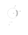
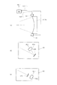
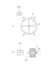
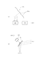
図6は、第1実施例において凹面反射鏡に入射するEUV光の光強度の角度分布の軸対称性を検出する検出系の構成を概略的に示す図である。図7は、図6の検出系の検出結果に基づいて光強度の角度分布がほぼ軸対称になるように光源本体を調整する調整系の構成を概略的に示す図である。図6(a)を参照すると、第1実施例にかかる検出系は、凹面反射鏡(12;24)の周囲に配置された4つの検出ユニット61〜64(図6(a)では63および64は不図示)と、各検出ユニット61〜64からの出力がそれぞれ供給される制御部65とを備えている。
[First embodiment]
FIG. 6 is a diagram schematically showing the configuration of a detection system for detecting the axial symmetry of the angular distribution of the light intensity of EUV light incident on the concave reflecting mirror in the first embodiment. FIG. 7 is a diagram schematically showing the configuration of an adjustment system that adjusts the light source body so that the angular distribution of light intensity is substantially axially symmetric based on the detection result of the detection system of FIG. Referring to FIG. 6A, the detection system according to the first embodiment includes four
4つの検出ユニット61〜64は、互いに同じ基本構成を有し、たとえば凹面反射鏡(12;24)の光軸に関してほぼ回転対称な位置に配置されている。一例として、第1検出ユニット61は、図6(b)に示すように、たとえばフォトダイオードのような光検出器61aと、光源本体(11;23,26,27)から凹面反射鏡(12;24)の周囲に達する光のうち所定波長(13.5nm)のEUV光だけを反射してフォトダイオード61aへ導く多層膜ミラー61bとを有する。
The four
あるいは、別の態様として、第1検出ユニット61は、図6(c)に示すように、フォトダイオード61aと、光源本体(11;23,26,27)から凹面反射鏡(12;24)の周囲に達する光のうち所定波長(13.5nm)近傍のEUV光だけを透過させてフォトダイオード61aへ導く選択フィルタ61cとを有する。ここで、多層膜ミラー61bは凹面反射鏡(12:24)の反射面(12a;24a)を形成する多層膜と同様の特性を有し、選択フィルタ61cは選択フィルタ(16;28)と同様の特性を有する。あるいは、凹面反射鏡(12:24)の反射面が放射状に複数に分割されている場合(ミラー基板が複数であっても良いし、1つの基板上に成膜されている多層膜が複数に分割されていても良い)、個々の反射面から放出される光電子または個々の反射面に流れる光電子流を測定し、EUV光強度分布をモニターしても良い。
Alternatively, as another aspect, as shown in FIG. 6C, the
第1実施例では、各検出ユニット61〜64からの出力が制御部65へそれぞれ供給される。制御部65は、各検出ユニット61〜64からの出力に基づいて、凹面反射鏡(12;24)に入射するEUV光の光強度の角度分布(面内分布)の軸対称性を検出する。なお、第1実施例において、各検出ユニットの内部構成、検出ユニットの数や配置などについては、図6の構成例に限定されることなく様々な変形例が可能である。
In the first embodiment, outputs from the
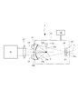
LPP光源タイプの光源ユニット2に適用される第1実施例の調整系は、図7(a)に示すように、レーザ光源26からのレーザ光の集光位置P2を変化させるための集光位置変化手段として、レーザ照射系(26,27)の光路中に配置されて光軸に対して傾動可能な平行平面板67と、制御部65からの指令を受けて平行平面板67の傾斜駆動およびレンズ27の光軸に沿った駆動を行うための駆動部66aとを有する。図7(a)では、平行平面板67がレーザ光源26とレンズ27との間に配置されているが、レンズ27と集光位置P2との間に平行平面板67を配置することもできる。
The adjustment system of the first embodiment applied to the LPP light source type
また、光源ユニット2に適用される第1実施例の調整系は、図7(b)に示すように、制御部65からの指令を受けてガスジェットノズル23の位置および姿勢を調整するためのノズル調整部66bを有する。ノズル調整部66bは、たとえばガスジェットノズル23を保持しているノズルステージ23bを適当なアクチュエータ(ピエゾ素子など)を介して駆動することにより、ガスジェットノズル23の位置および姿勢を調整し、ひいてはガスジェットノズル23から噴射されるターゲットガス23aの経路を変化させる。なお、ガス状のターゲット材料に代えて、液体状のターゲット材料を連続的に噴射したり、液滴として供給したりしても良い。
The adjustment system of the first embodiment applied to the
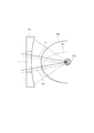
図8は、液滴状または液柱状ターゲットに対してレーザ光の集光位置が相対的に変化すると凹面反射鏡に入射するEUV光の光強度の角度分布が変化する様子を模式的に示す図である。図8において、紙面に垂直な方向に沿って供給されるターゲット23aのほぼ中心位置に、レーザ照射系(26,27)からのレーザ光L1(図中実線で示す)が集光する場合、凹面反射鏡24に入射するEUV光の光強度の角度分布は図中実線D1で示すようにレーザ光軸に関してほぼ軸対称になる。
FIG. 8 is a diagram schematically showing how the angular distribution of the light intensity of EUV light incident on the concave reflecting mirror changes when the condensing position of the laser light changes relative to the droplet-like or liquid column-like target. It is. In FIG. 8, when the laser beam L1 (shown by the solid line in the figure) from the laser irradiation system (26, 27) is condensed at a substantially central position of the
しかしながら、ターゲット23aの中心から実質的に外れた位置に、レーザ照射系(26,27)からのレーザ光L2(図中破線で示す)が集光する場合、凹面反射鏡24に入射するEUV光の光強度の角度分布は図中破線D2で示すようにレーザ光軸に関して実質的に軸非対称になる。換言すれば、ターゲット23aに対してレーザ光の集光位置P2を相対的に変化させることにより、凹面反射鏡24に入射するEUV光の光強度角度分布の軸対称性を調整することができる。
However, when the laser light L2 (shown by a broken line in the figure) from the laser irradiation system (26, 27) is condensed at a position substantially deviated from the center of the
そこで、光源ユニット2に適用される第1実施例の調整系では、制御部65からの指令を受けた駆動部66aを介して、平行平面板67の傾斜駆動を行うことにより、また必要に応じてレンズ27の光軸方向駆動を行うことにより、レーザ光源26からのレーザ光の集光位置P2を変化させる。また、制御部65からの指令を受けたノズル調整部66bを介して、ノズル23の位置および姿勢を調整し、ひいてはノズル23から噴射されるターゲット23aの経路を変化させる。こうして、レーザ光の集光位置P2の変化やターゲット23aの経路の変化により、凹面反射鏡24に入射するEUV光の光強度の角度分布をほぼ軸対称に調整することができる。ノズル調整部66bによりターゲット位置が一定になるように制御すると、発光位置を変えずに角度分布を調整することができる。
Therefore, in the adjustment system of the first embodiment applied to the
一方、DPP光源タイプの光源ユニット1に適用される第1実施例の調整系は、図7(c)に示すように、制御部65からの指令を受けて放電に際して一対の電極(11a,11b)を放電軸廻りに回転させるための電極駆動手段として、たとえばモータのような電極駆動部66cを有する。この場合、制御部65からの指令を受けた電極駆動部66cの作用により、一対の電極(11a,11b)が放電軸廻りに回転し、ひいては凹面反射鏡12に入射するEUV光の光強度分布も軸回転する。その結果、いわゆる平均化効果により、凹面反射鏡12に入射するEUV光の光強度の角度分布をほぼ軸対称に調整することができる。
On the other hand, as shown in FIG. 7C, the adjustment system of the first embodiment applied to the DPP light source type
[第2実施例]
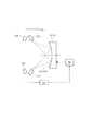
図9は、第2実施例において凹面反射鏡により一旦集光して発散するEUV光の光強度の角度分布の軸対称性を検出する検出系の構成を概略的に示す図である。図10は、図9の検出系の検出結果に基づいて光強度の角度分布がほぼ軸対称になるように凹面反射鏡の位置および姿勢を調整する調整系の構成を概略的に示す図である。図9(a)を参照すると、第2実施例にかかる検出系は、凹面反射鏡(12;24)により所定位置P1で一旦集光して発散するEUV光の有効光束L3の周囲に配置された4つの検出ユニット71〜74(図9(a)では73および74は不図示)と、各検出ユニット71〜74からの出力がそれぞれ供給される制御部75とを備えている。
[Second Embodiment]
FIG. 9 is a diagram schematically showing the configuration of a detection system for detecting the axial symmetry of the angular distribution of the light intensity of EUV light once condensed and diverged by the concave reflecting mirror in the second embodiment. FIG. 10 is a diagram schematically showing a configuration of an adjustment system that adjusts the position and posture of the concave reflecting mirror so that the angular distribution of light intensity is substantially axially symmetric based on the detection result of the detection system of FIG. . Referring to FIG. 9A, the detection system according to the second embodiment is arranged around the effective light beam L3 of EUV light that is once condensed and diverged at a predetermined position P1 by the concave reflecting mirror (12; 24). In addition, four
4つの検出ユニット71〜74は、第1実施例の検出ユニット61〜64と同様に、互いに同じ基本構成を有し、たとえば所定位置P1を介したEUV光の有効光束L3の中心軸線に関してほぼ回転対称な位置に配置されている。一例として、第1検出ユニット71は、図9(b)に示すように、たとえばフォトダイオードのような光検出器71aと、光源本体(11;23,26,27)から有効光束L3の周囲に達する光のうち所定波長(13.5nm)のEUV光だけを透過させてフォトダイオード71aへ導く選択フィルタ71bとを有する。
The four
あるいは、別の態様として、第2検出ユニット71は、図9(c)に示すように、フォトダイオード71aと、光源本体(11;23,26,27)から有効光束L3の周囲に達する光のうち所定波長(13.5nm)のEUV光だけを反射してフォトダイオード71aへ導く多層膜ミラー71cとを有する。ここで、多層膜ミラー71cは第1実施例の多層膜ミラー61bと同様の特性を有し、選択フィルタ71bは第1実施例の選択フィルタ61cと同様の特性を有する。なお、多層膜ミラーと選択フィルタとを併用しても良い。
Alternatively, as another aspect, as shown in FIG. 9C, the
第2実施例では、各検出ユニット71〜74からの出力が制御部75へそれぞれ供給される。制御部75は、各検出ユニット71〜74からの出力に基づいて、凹面反射鏡(12;24)により所定位置P1で一旦集光して発散するEUV光の光強度の角度分布(面内分布)の軸対称性を検出する。なお、第2実施例においても、各検出ユニットの内部構成、検出ユニットの数や配置などについては、図9の構成例に限定されることなく様々な変形例が可能である。
In the second embodiment, outputs from the
第2実施例の調整系は、図10に示すように、制御部75からの指令を受けて凹面反射鏡(12;24)の位置および姿勢を調整する反射鏡調整部76を有する。反射鏡調整部76は、凹面反射鏡(12;24)を適当なアクチュエータ(ピエゾ素子など)を介して駆動することにより、その位置および姿勢を変化させる。こうして、制御部75からの指令を受けた反射鏡調整部76の作用により、凹面反射鏡(12;24)の位置および姿勢を変化させて、所定位置P1で一旦集光して発散するEUV光の角度分布をほぼ軸対称に調整することができる。
As shown in FIG. 10, the adjustment system of the second embodiment has a reflecting
なお、第2実施例の調整系は、LPP光源タイプの光源ユニット2に適用される場合、必要に応じて、図7(a)に示す集光位置変化手段(27,66a,67)や、図7(b)に示すノズル調整手段(66b)を有することが好ましい。この場合、図10に示す反射鏡調整手段(76)と集光位置変化手段(27,66a,67)やノズル調整手段(66b)との協働作用により、所定位置P1で一旦集光して発散するEUV光の角度分布をさらに正確に且つ迅速に調整することができる。
When the adjustment system of the second embodiment is applied to the
また、第2実施例の調整系は、DPP光源タイプの光源ユニット1に適用される場合、必要に応じて、電極駆動手段(66c)を有することが好ましい。この場合、図10に示す反射鏡調整手段(76)と電極駆動手段(66c)との協働作用により、所定位置P1で一旦集光して発散するEUV光の角度分布をさらに正確に且つ迅速に調整することができる。
In addition, when applied to the DPP light source type
[第3実施例]
図11は、第3実施例において凹面反射鏡で反射されたEUV光の集光位置を検出する検出系の構成、およびEUV光の集光位置を調整する調整系の構成を概略的に示す図である。第3実施例にかかる検出系は、LPP光源タイプの光源ユニット2に適用される場合、図11(a)に示すように、凹面反射鏡24で反射されたEUV光が集光すべき所定位置P1に配置されたピンホール部材29の光入射側の面に取り付けられた二次元光検出器81と、二次元光検出器81からの出力が供給される制御部82とを備えている。
[Third embodiment]
FIG. 11 is a diagram schematically showing a configuration of a detection system that detects a condensing position of EUV light reflected by a concave reflecting mirror and a configuration of an adjustment system that adjusts the condensing position of EUV light in the third embodiment. It is. When the detection system according to the third embodiment is applied to the LPP light source type
二次元光検出器81は、たとえばピンホール部材29の光入射側の面を4分割して得られる扇状の各分割領域にフォトダイオード81a〜81dを配置することにより形成されている。この場合、凹面反射鏡24で反射されたEUV光の集光位置がピンホール部材29のピンホール29aから位置ずれすると、4つのフォトダイオード81a〜81dのうちの少なくとも1つのフォトダイオードの出力信号が変化する。
The two-dimensional photodetector 81 is formed, for example, by arranging
第3実施例では、二次元光検出器81としての4つのフォトダイオード81a〜81dからの出力が制御部82へそれぞれ供給される。制御部82は、各フォトダイオード81a〜81dからの出力に基づいて、凹面反射鏡24で反射されたEUV光の集光位置および強度分布を検出する。同様に、DPP光源タイプの光源ユニット1に適用する場合にも、凹面反射鏡12で反射されたEUV光が集光すべき所定位置P1に4つのフォトダイオード81a〜81dを配置すれば良い。
In the third embodiment, outputs from the four
なお、第3実施例において、ピンホール部材の光入射面における分割数をさらに増やすことにより、EUV光の集光位置や強度分布をさらに高精度に検出することができる。また、複数のフォトダイオードを用いる構成に限定されることなく、単に複数の分割された金属板を集光位置の近傍に配置し、それぞれの金属板から放出される光電子または流れる光電子流を計測しても良い。また、ピンホール部材の光入射面に配置した二次元撮像素子を用いる構成も可能であり、凹面反射鏡(12;24)で反射されたEUV光の集光位置を検出する検出系について、図11の構成例に限定されることなく様々な変形例が可能である。 In the third embodiment, by further increasing the number of divisions on the light incident surface of the pinhole member, it is possible to detect the EUV light focusing position and intensity distribution with higher accuracy. In addition, the present invention is not limited to a configuration using a plurality of photodiodes, and a plurality of divided metal plates are simply arranged in the vicinity of the condensing position, and photoelectrons emitted from the respective metal plates or a flowing photoelectron current are measured. May be. In addition, a configuration using a two-dimensional imaging device arranged on the light incident surface of the pinhole member is also possible, and a detection system for detecting a condensing position of EUV light reflected by the concave reflecting mirror (12; 24) is shown in FIG. Various modifications are possible without being limited to the eleven configuration examples.
第3実施例の調整系は、制御部82からの指令を受けて凹面反射鏡(12;24)の位置および姿勢を調整する反射鏡調整部76(図10を参照)を有する。反射鏡調整部76は、凹面反射鏡(12;24)を適当なアクチュエータ(ピエゾ素子など)を介して駆動することにより、その位置および姿勢を変化させる。こうして、制御部82からの指令を受けた反射鏡調整部76の作用により、凹面反射鏡(12;24)の位置および姿勢を変化させて、凹面反射鏡(12;24)で反射されたEUV光の集光位置がほぼ所定位置P1になるように調整することができる。
The adjusting system of the third embodiment has a reflecting mirror adjusting unit 76 (see FIG. 10) that receives a command from the
また、第3実施例の調整系は、LPP光源タイプの光源ユニット2に適用される場合、プラズマPからのEUV光の発光位置を変化させるための発光位置変化手段として、図7(a)に示す集光位置変化手段(27,66a,67)および図7(b)に示すノズル調整手段(66b)を有する。こうして、制御部82からの指令を受けた集光位置変化手段(27,66a,67)およびノズル調整手段(66b)の作用により、プラズマPからのEUV光の発光位置を変化させて、凹面反射鏡24で反射されたEUV光の集光位置がほぼ所定位置P1になるように調整することができる。
When the adjustment system of the third embodiment is applied to the
また、第3実施例の調整系は、DPP光源タイプの光源ユニット1に適用される場合、図11(b)に示すように、制御部82からの指令を受けて一対の電極(11a,11b)の位置を変化させる電極位置変化手段83を有する。電極位置変化手段83は、一対の電極(11a,11b)を適当なアクチュエータ(ピエゾ素子など)を介して一体的に駆動することにより、その位置を変化させる。こうして、制御部82からの指令を受けた電極位置変化手段83の作用により、一対の電極(11a,11b)の位置を変化させ、ひいてはプラズマPからのEUV光の発光位置を変化させて、凹面反射鏡12で反射されたEUV光の集光位置がほぼ所定位置P1になるように調整することができる。
Further, when the adjustment system of the third embodiment is applied to the DPP light source type
[第4実施例]
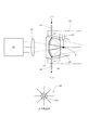
図12は、第4実施例においてプラズマからのEUV光の発光位置を検出する検出系の構成を概略的に示す図である。図12を参照すると、第4実施例にかかる検出系は、プラズマPから凹面反射鏡(12;24)へ入射するEUV光の有効光束の周囲に配置された2つの検出ユニット91および92と、各検出ユニット91および92からの出力がそれぞれ供給される制御部93とを備えている。2つの検出ユニット91および92は、互いに同じ基本構成を有する。
[Fourth embodiment]
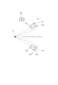
FIG. 12 is a diagram schematically showing the configuration of a detection system for detecting the emission position of EUV light from plasma in the fourth embodiment. Referring to FIG. 12, the detection system according to the fourth embodiment includes two
すなわち、各検出ユニット91(92)は、たとえば二次元CCDのような二次元撮像素子91a(92a)と、プラズマPと二次元CCD91a(92a)との間の光路中に配置されたピンホール部材91b(92b)を有する。第4実施例では、各検出ユニット91および92からの出力が制御部93へそれぞれ供給される。制御部93は、各検出ユニット91および92からの出力に基づいて、プラズマPからのEUV光の発光位置を検出する。なお、第4実施例においても、各検出ユニットの内部構成、検出ユニットの数や配置などについては、図12の構成例に限定されることなく様々な変形例が可能である。
That is, each detection unit 91 (92) is, for example, a two-dimensional imaging element 91a (92a) such as a two-dimensional CCD, and a pinhole member disposed in the optical path between the plasma P and the two-dimensional CCD 91a (92a). 91b (92b). In the fourth embodiment, outputs from the
第4実施例の調整系は、DPP光源タイプの光源ユニット1に適用される場合、図11(b)に示すように、制御部93からの指令を受けて一対の電極(11a,11b)の位置を調整する電極位置変化手段83を有する。こうして、制御部93からの指令を受けた電極位置変化手段83の作用により、一対の電極(11a,11b)の位置(例えばX,Y,Z方向)を変化させ、ひいてはプラズマPからのEUV光の発光位置がほぼ所定位置になるように調整することができる。
When the adjustment system of the fourth embodiment is applied to the
第4実施例の調整系は、LPP光源タイプの光源ユニット2に適用される場合、図7(a)に示す集光位置変化手段(27,66a,67)および図7(b)に示すノズル調整手段(66b)を有する。こうして、制御部93からの指令を受けた集光位置変化手段(27,66a,67)およびノズル調整手段(66b)の作用により、プラズマPからのEUV光の発光位置がほぼ所定位置になるように調整することができる。
When the adjustment system of the fourth embodiment is applied to the
[第5実施例]
図13は、第5実施例においてオプティカルインテグレータに入射するEUV光の光強度の角度分布の軸対称性を検出する検出系の構成、および光強度の角度分布をほぼ軸対称に調整する調整系の構成を概略的に示す図である。図13(a)を参照すると、第5実施例にかかる検出系は、第1フライアイミラー32aを構成する多数の要素ミラー32aaのうちの複数の要素ミラーに接続された電流計101と、この電流計101の出力が供給される制御部102とを備えている。
[Fifth embodiment]
FIG. 13 shows a configuration of a detection system for detecting the axial symmetry of the angular distribution of the light intensity of EUV light incident on the optical integrator in the fifth embodiment, and an adjustment system for adjusting the angular distribution of the light intensity to be substantially axially symmetric. It is a figure which shows a structure schematically. Referring to FIG. 13A, the detection system according to the fifth embodiment includes an
要素ミラー32aaにEUV光が入射すると、入射光の強度に応じた数の光電子が金属の表面から放出される。電流計101では、各要素ミラーからの光電子の放出により発生する電流すなわち光電子電流を検出する。第5実施例では、電流計101の出力が制御部102へ供給される。制御部102は、電流計101からの出力に基づいて、すなわち各要素ミラーで発生した光電子電流量に関する情報に基づいて、第1フライアイミラー32aに入射するEUV光ひいてはオプティカルインテグレータ32に入射するEUV光の光強度の角度分布の軸対称性を検出する。なお、検出対象の要素ミラーの数と同数の電流計101を用いてもよいし、1つあるいは少数の電流計101により時分割方式で各要素ミラーからの光電子電流を順次検出してもよい。
When EUV light enters the element mirror 32aa, a number of photoelectrons corresponding to the intensity of the incident light are emitted from the metal surface. The
第5実施例の調整系は、図13(b)に示すように、制御部102からの指令を受けてコリメータミラー31の位置および姿勢を調整するミラー調整部103を有する。ミラー調整部103は、コリメータミラー31を適当なアクチュエータ(ピエゾ素子など)を介して駆動することにより、その位置および姿勢を変化させる。こうして、制御部102からの指令を受けたミラー調整部103の作用により、コリメータミラー31の位置および姿勢を変化させて、オプティカルインテグレータ32に入射するEUV光の光強度の角度分布(面内分布)をほぼ軸対称に調整することができる。あるいは、光学素子の汚染などによりマスク上の照度分布が均一ではなくなったときに、コリメータミラー31の位置または姿勢を変化させることにより、角度分布(面内分布)の軸対称性を意図的に悪化させてマスク上の照度分布が均一になるように制御しても良い。
As shown in FIG. 13B, the adjustment system of the fifth embodiment has a
また、第5実施例の調整系は、制御部102からの指令を受けて凹面反射鏡(12;24)の位置および姿勢を調整する反射鏡調整部76(図10を参照)を有する。この場合、制御部102からの指令を受けた反射鏡調整部76の作用により、凹面反射鏡(12;24)の位置および姿勢を変化させて、オプティカルインテグレータ32に入射するEUV光の光強度の角度分布をほぼ軸対称に調整することができる。
Further, the adjustment system of the fifth embodiment has a reflecting mirror adjusting unit 76 (see FIG. 10) that receives a command from the
以上のように、本実施形態では、電極やノズルの変形または消耗、消耗した電極やノズルや凹面反射鏡の交換取付け誤差、ターゲットガスに対するレーザ光の集光位置の変化など様々な原因により、凹面反射鏡(12;24)に入射するEUV光や、凹面反射鏡(12;24)により一旦集光されて発散しつつ光源ユニット(1;2)から供給されるEUV光の光強度の角度分布(面内分布)が実質的に軸非対称になることがあっても、上述の第1実施例または第2実施例の構成を適用することにより光強度の角度分布がほぼ軸対称になるように調整することができる。すなわち、本実施形態の光源ユニットでは、所望の光強度角度分布(面内分布)を有するEUV光を安定的に供給することができる。 As described above, according to the present embodiment, the concave surface is caused by various causes such as deformation or wear of the electrode or nozzle, replacement error of the worn electrode, nozzle or concave reflecting mirror, or a change in the focusing position of the laser beam with respect to the target gas. Angular distribution of light intensity of EUV light incident on the reflecting mirror (12; 24) and EUV light supplied from the light source unit (1; 2) while being once condensed and diverged by the concave reflecting mirror (12; 24) Even if the (in-plane distribution) may be substantially axially asymmetric, by applying the configuration of the first embodiment or the second embodiment described above, the angular distribution of the light intensity is substantially axially symmetric. Can be adjusted. That is, in the light source unit of the present embodiment, EUV light having a desired light intensity angle distribution (in-plane distribution) can be stably supplied.
また、本実施形態では、上述したような様々な原因により、凹面反射鏡(12;24)で反射されたEUV光の集光位置やプラズマPからのEUV光の発光位置が変化することがあっても、上述の第3実施例または第4実施例の構成を適用することにより集光位置や発光位置が所定位置になるように調整することができる。すなわち、本実施形態の光源ユニットでは、発光位置(プラズマ生成位置)や集光位置をほぼ所定位置に安定的に維持することができる。 In the present embodiment, the EUV light condensing position reflected by the concave reflecting mirror (12; 24) and the EUV light emitting position from the plasma P may change due to various causes as described above. However, by applying the configuration of the third embodiment or the fourth embodiment described above, the light condensing position and the light emitting position can be adjusted to a predetermined position. That is, in the light source unit of the present embodiment, the light emission position (plasma generation position) and the light collection position can be stably maintained at substantially predetermined positions.
さらに、本実施形態では、上述したような様々な原因により、オプティカルインテグレータ32に入射するEUV光の光強度の角度分布(面内分布)が実質的に軸非対称になることがあっても、上述の第5実施例の構成を適用することにより光強度の角度分布がほぼ軸対称になるように調整することができる。すなわち、本実施形態の照明光学装置では、所望の光強度角度分布(面内分布)を有するEUV光で被照射面(マスクM)を安定的に照明することができる。
Furthermore, in the present embodiment, even if the angular distribution (in-plane distribution) of the EUV light incident on the
したがって、本実施形態の露光装置では、所望の光強度角度分布(面内分布)を有するEUV光を安定的に供給する光源ユニット、発光位置や集光位置をほぼ所定位置に安定的に維持する光源ユニット、または所望の光強度角度分布(面内分布)を有するEUV光で被照射面を安定的に照明する照明光学装置を用いて、所望の照明条件(例えば均一な照射光量分布)のもとでマスクパターンを感光性基板上に忠実に転写することができる。なお、本実施形態では、第1乃至第5実施例の構成をそれぞれ単独で適用してもよいし、複数の実施例の構成を適宜組み合わせて適用してもよい。 Therefore, in the exposure apparatus of the present embodiment, the light source unit that stably supplies EUV light having a desired light intensity angle distribution (in-plane distribution), the light emission position and the light collection position are stably maintained at substantially predetermined positions. Using a light source unit or an illumination optical device that stably illuminates a surface to be irradiated with EUV light having a desired light intensity angle distribution (in-plane distribution), a desired illumination condition (for example, uniform irradiation light amount distribution) Thus, the mask pattern can be faithfully transferred onto the photosensitive substrate. In the present embodiment, the configurations of the first to fifth examples may be applied alone, or the configurations of a plurality of examples may be combined as appropriate.
ところで、本実施形態では、凹面反射鏡(12;24)の反射面(12a;24a)がプラズマPに直接さらされ、プラズマPからの輻射熱の影響およびEUV光の照射熱の影響を受けるため、凹面反射鏡(12;24)を交換することが必要になる。そこで、凹面反射鏡(12;24)を容易に且つ正確に交換するために、凹面反射鏡(12;24)の反射面(12a;24a)の位置(および姿勢)を計測するための計測系と、この計測系の計測結果に基づいて凹面反射鏡(12;24)の反射面(12a;24a)を所定の位置に位置決めするための駆動系とを備えていることが好ましい。 By the way, in this embodiment, since the reflecting surface (12a; 24a) of the concave reflecting mirror (12; 24) is directly exposed to the plasma P, it is affected by the radiation heat from the plasma P and the irradiation heat of the EUV light. It will be necessary to replace the concave reflector (12; 24). Therefore, in order to easily and accurately replace the concave reflecting mirror (12; 24), a measurement system for measuring the position (and orientation) of the reflecting surface (12a; 24a) of the concave reflecting mirror (12; 24). And a drive system for positioning the reflecting surface (12a; 24a) of the concave reflecting mirror (12; 24) at a predetermined position based on the measurement result of the measuring system.
図14は、凹面反射鏡の反射面の位置を計測する計測系の構成および凹面反射鏡の反射面を所定の位置に位置決めする駆動系の構成を概略的に示す図である。図14に示す計測系は、たとえば3つの計測ユニット51〜53(53は不図示)と、各計測ユニット51〜53からの出力がそれぞれ供給される制御部54とを備えている。3つの計測ユニット51〜53は、互いに同じ基本構成を有する。すなわち、各計測ユニット51(52,53)は、凹面反射鏡(12;24)の反射面(12a;24a)に向かって計測光を射出するための半導体レーザ51a(52a,53a)と、凹面反射鏡(12;24)の反射面(12a;24a)で反射された計測光の位置を検出するための二次元CCD51b(52b,53b)とを有する。
FIG. 14 is a diagram schematically showing a configuration of a measurement system that measures the position of the reflecting surface of the concave reflecting mirror and a configuration of a drive system that positions the reflecting surface of the concave reflecting mirror at a predetermined position. The measurement system shown in FIG. 14 includes, for example, three measurement units 51 to 53 (53 is not shown), and a
制御部54は、各計測ユニット51〜53からの出力に基づいて、凹面反射鏡(12;24)の反射面(12a;24a)の位置(および姿勢)を計測する。こうして、制御部54からの指令を受けた駆動系55(図10の反射鏡調整部76に対応)が、適当なアクチュエータ(ピエゾ素子など)を介して凹面反射鏡(12;24)を駆動することにより、凹面反射鏡(12;24)の反射面(12a;24a)が所定の位置に位置決めされる。なお、図14においては、レーザダイオード(半導体レーザ)を用いたが、これに限定されることなく、発光ダイオード(LED)とレンズ等とで構成しても良いし、CCDに代えて4分割フォトダイオードを用いても良い。また、凹面反射鏡(12;24)の反射面(12a;24a)の位置を計測するための計測系の構成については、図14の構成例に限定されることなく、様々な変形例が可能である。
The
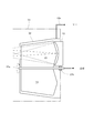
また、本実施形態では、プラズマPからのEUV光の輻射に際して放出される飛散粒子(デブリ)が凹面反射鏡(12;24)の反射面(12a;24a)に付着すると、凹面反射鏡(12;24)の反射特性(光学特性)が劣化し、その交換頻度が増大してしまう。そこで、本実施形態では、プラズマPから放出される飛散粒子をプラズマPと凹面反射鏡(12;24)との間の光路中において除去するための飛散粒子除去機構を備えていることが好ましい。 Further, in the present embodiment, when scattered particles (debris) emitted upon radiation of EUV light from the plasma P adhere to the reflecting surface (12a; 24a) of the concave reflecting mirror (12; 24), the concave reflecting mirror (12 24) the reflection characteristic (optical characteristic) deteriorates, and the exchange frequency increases. Therefore, in the present embodiment, it is preferable to include a scattering particle removing mechanism for removing scattering particles emitted from the plasma P in the optical path between the plasma P and the concave reflecting mirror (12; 24).
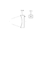
図15は、図3に示すDPP光源タイプの光源ユニットに適用可能な飛散粒子除去機構の一例を概略的に示す図である。図15の飛散粒子除去機構は、凹面反射鏡12を覆うカバー18を備えている。カバー18の中には、回転軸19aを中心として回転可能な回転羽19(飛散粒子阻止部材)が収納されている。回転軸19aは、チャンバー13の外部にある駆動系(不図示)の作用により、回転導入部19bを介して回転駆動される。
FIG. 15 is a diagram schematically showing an example of a scattering particle removal mechanism applicable to the DPP light source type light source unit shown in FIG. The scattered particle removal mechanism in FIG. 15 includes a
回転軸19a内には冷媒(例えば、冷却水、フロリナート、ヘリウム(He)ガスなど)が流れるように構成されており、この冷媒の作用により回転羽19が冷却される。カバー18には配管18aが取り付けられており、バッファガス(He,Ar,N2,Ne,Kr,H2など)が配管18aを介して凹面反射鏡12の周辺からカバー18内へ導入される。
A refrigerant (for example, cooling water, fluorinate, helium (He) gas, etc.) flows through the
図15の飛散粒子除去機構において、一対の電極(11a,11b)近傍のプラズマPから放出された飛散粒子は、チャンバー13内に導入されたバッファガス分子と衝突してその運動エネルギーが減少し、チャンバー13内を浮遊する。そして、カバー18内に入った飛散粒子は、回転羽19に衝突することにより回転羽19に付着する。これにより、カバー18内に侵入した飛散粒子は回転羽19により排除されて凹面反射鏡12に実質的に達することなく、飛散粒子の付着などによる凹面反射鏡12の反射率低下を防ぐことができる。
In the scattering particle removal mechanism of FIG. 15, the scattering particles emitted from the plasma P in the vicinity of the pair of electrodes (11a, 11b) collide with the buffer gas molecules introduced into the
特に、回転羽19の冷却により飛散粒子が付着・堆積し易くなっているので、より効果的に飛散粒子を排除することができる。また、凹面反射鏡12の近傍からバッファガスがカバー18内に導入され、カバー18の開口部からバッファガスが外部へ流出するように構成することにより、このガス流の作用によってもカバー18内に侵入した飛散粒子を排除することができるのでより好ましい。また、回転羽19は交換可能であることが好ましい。回転羽19の回転速度はできるだけ速い方が、マスク上での光量ムラを低減する上で好ましい。例えば、毎分10回転以上とすれば良い。また、EUV光の発光の繰り返し周波数の比が整数倍にならないようにすると、羽根が光束を遮る位置が同じにならなくなるので良い。あるいは、回転速度を変えながら羽根を回してもよく、特に回転速度をランダムにするとより好ましい。なお、上述の説明ではプラズマPと凹面反射鏡12との間に飛散粒子除去機構を配置しているが、集光光学系を構成する一対の反射鏡間(たとえば凹面反射鏡と凸面反射鏡のような複数の反射鏡の間)の光路中において飛散粒子を除去するために、図15に示すような飛散粒子除去機構を配置することもできる。
In particular, since the scattered particles are easily attached and deposited by cooling the
図16は、図4に示すLPP光源タイプの光源ユニットに適用可能な飛散粒子除去機構の一例を概略的に示す図である。図16の飛散粒子除去機構は、凹面反射鏡24を覆うカバー40を備えている。カバー40には配管41が取り付けられ、バッファガス(He,Ar,Kr,N2,Ne,H2など)が配管41を介してカバー40内に導入される。カバー40の中において、プラズマPと凹面反射鏡24との間の光路中にフィン42が設けられている。フィン42の中心には開口部42aが形成され、レーザ光源26から射出されて凹面反射鏡24を通過したレーザ光は開口部42aを介してプラズマPの位置に達する。
FIG. 16 is a diagram schematically showing an example of a scattering particle removal mechanism applicable to the LPP light source type light source unit shown in FIG. The scattered particle removal mechanism in FIG. 16 includes a
図16の飛散粒子除去機構において、プラズマPから放出された飛散粒子は、チャンバー21内に導入されたバッファガス分子と衝突してその運動エネルギーが減少し、チャンバー21内を浮遊する。そして、カバー40内に入った飛散粒子は、フィン42(飛散粒子阻止部材)に衝突することによりフィン42に付着する。これにより、カバー40内に侵入した飛散粒子はフィン42により排除されて凹面反射鏡24に実質的に達することなく、凹面反射鏡24の反射率低下を防ぐことができる。
In the scattered particle removal mechanism of FIG. 16, the scattered particles emitted from the plasma P collide with the buffer gas molecules introduced into the
凹面反射鏡24の近傍からバッファガスを導入し、カバー40の開口部からガスが外部へ流出するように構成することにより、このガス流の作用によってもカバー40内に侵入した飛散粒子を排除することができるのでより好ましい。フィン40の断面形状を図16に示すような形状にすることにより、光の損失を最小限に抑えることができる。フィン40を冷却することにより飛散粒子が付着・堆積し易くなるので、より効果的に飛散粒子を排除することができる。また、フィン40をレーザ光軸(EUV光の光軸)の周りに回転させても飛散粒子の除去能力が増すので好ましい。また、フィン40は交換可能であることが好ましい。
By introducing a buffer gas from the vicinity of the concave reflecting
なお、上述の実施形態では、図3に示すような基本構成を有するDPP光源タイプの光源ユニット1、および図4に示すような基本構成を有するLPP光源タイプの光源ユニット2に対して本発明を適用している。しかしながら、これに限定されることなく、一般的なDPP光源タイプの光源ユニットおよびLPP光源タイプの光源ユニットに対して本発明を適用することができる。具体的には、図3に示す構成とは異なり、たとえば一対の電極間の放電により生成されたプラズマから輻射されたEUV光を斜入射ミラーやシュバルツシルド光学系などを用いて集光する構成を有するLPP光源タイプの光源ユニットに対しても本発明を適用することができる。また、図4に示す構成とは異なり、たとえば凹面反射鏡を通過することなくターゲットにレーザ光を集光させる構成を有するLPP光源タイプの光源ユニットに対しても本発明を適用することができる。
In the above-described embodiment, the present invention is applied to the DPP light source type
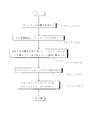
上述の実施形態にかかる露光装置では、照明系によってマスクを照明し(照明工程)、投影光学系を用いてマスクに形成された転写用のパターンを感光性基板に露光する(露光工程)ことにより、マイクロデバイス(半導体素子、撮像素子、液晶表示素子、薄膜磁気ヘッド等)を製造することができる。以下、本実施形態の露光装置を用いて感光性基板としてのウェハ等に所定の回路パターンを形成することによって、マイクロデバイスとしての半導体デバイスを得る際の手法の一例につき図17のフローチャートを参照して説明する。 In the exposure apparatus according to the above-described embodiment, the illumination system illuminates the mask (illumination process), and exposes the transfer pattern formed on the mask using the projection optical system onto the photosensitive substrate (exposure process). Microdevices (semiconductor elements, imaging elements, liquid crystal display elements, thin film magnetic heads, etc.) can be manufactured. Hereinafter, referring to the flowchart of FIG. 17 for an example of a method for obtaining a semiconductor device as a micro device by forming a predetermined circuit pattern on a wafer or the like as a photosensitive substrate using the exposure apparatus of the present embodiment. I will explain.
先ず、図17のステップ301において、1ロットのウェハ上に金属膜が蒸着される。次のステップ302において、その1ロットのウェハ上の金属膜上にフォトレジストが塗布される。その後、ステップ303において、本実施形態の露光装置を用いて、マスク(レチクル)上のパターンの像がその投影光学系を介して、その1ロットのウェハ上の各ショット領域に順次露光転写される。 First, in step 301 of FIG. 17, a metal film is deposited on one lot of wafers. In the next step 302, a photoresist is applied on the metal film on the one lot of wafers. Thereafter, in step 303, using the exposure apparatus of the present embodiment, the pattern image on the mask (reticle) is sequentially exposed and transferred to each shot area on the wafer of one lot via the projection optical system. .
その後、ステップ304において、その1ロットのウェハ上のフォトレジストの現像が行われた後、ステップ305において、その1ロットのウェハ上でレジストパターンをマスクとしてエッチングを行うことによって、マスク上のパターンに対応する回路パターンが、各ウェハ上の各ショット領域に形成される。その後、更に上のレイヤの回路パターンの形成等を行うことによって、半導体素子等のデバイスが製造される。上述の半導体デバイス製造方法によれば、極めて微細な回路パターンを有する半導体デバイスをスループット良く得ることができる。 Thereafter, in step 304, the photoresist on the one lot of wafers is developed, and in step 305, the resist pattern is etched on the one lot of wafers to form a pattern on the mask. Corresponding circuit patterns are formed in each shot area on each wafer. Thereafter, a device pattern such as a semiconductor element is manufactured by forming a circuit pattern of an upper layer. According to the semiconductor device manufacturing method described above, a semiconductor device having an extremely fine circuit pattern can be obtained with high throughput.
1 DPP光源タイプの光源ユニット
2 LPP光源タイプの光源ユニット
3 照明光学系
5 マスクステージ
7 ウェハステージ
11 光源本体
11a,11b 電極
12,24 凹面反射鏡
13 チャンバ
15 開口部
16,28 選択フィルタ
21 真空容器
23 ガスジェットノズル
26 レーザ光源
29 ピンホール部材
31 コリメータミラー
32 オプティカルインテグレータ
32a,32b フライアイミラー
M マスク
PL 投影光学系
W ウェハ
DESCRIPTION OF
Claims (35)
前記光源本体から輻射されたEUV光を所定の方向に反射するための反射鏡と、
前記反射鏡に入射するEUV光の光強度の角度分布の軸対称性を検出するための検出系と、
前記検出系の検出結果に基づいて、前記光強度の角度分布がほぼ軸対称になるように前記光源本体を調整するための調整系とを備えていることを特徴とする光源ユニット。 A light source body that converts the target material into plasma and radiates EUV light from the generated plasma;
A reflecting mirror for reflecting the EUV light radiated from the light source body in a predetermined direction;
A detection system for detecting the axial symmetry of the angular distribution of the light intensity of the EUV light incident on the reflecting mirror;
A light source unit comprising: an adjustment system for adjusting the light source body so that the angular distribution of the light intensity is substantially axially symmetric based on a detection result of the detection system.
前記調整系は、前記レーザ光の集光位置を変化させるための集光位置変化手段を有することを特徴とする請求項1乃至4のいずれか1項に記載の光源ユニット。 The light source body includes a nozzle for supplying the target material, and a laser irradiation system for irradiating a laser beam so as to collect light with respect to the target material supplied from the nozzle,
5. The light source unit according to claim 1, wherein the adjustment system includes a condensing position changing unit configured to change a condensing position of the laser light.
前記調整系は、前記ノズルの位置および姿勢を調整するためのノズル調整手段と、レーザ光の集光位置を変化させるための集光位置変化手段とを有することを特徴とする請求項1乃至4のいずれか1項に記載の光源ユニット。 The light source body includes a nozzle for supplying the target material, and a laser irradiation system for irradiating a laser beam so as to collect light with respect to the target material supplied from the nozzle,
The adjustment system includes nozzle adjustment means for adjusting the position and posture of the nozzle, and condensing position changing means for changing the condensing position of the laser beam. The light source unit according to any one of the above.
前記調整系は、放電に際して前記一対の電極を放電軸廻りに回転させるための電極駆動手段を有することを特徴とする請求項1乃至4のいずれか1項に記載の光源ユニット。 The light source body has a pair of electrodes for converting the target material into plasma by discharge,
5. The light source unit according to claim 1, wherein the adjustment system includes electrode driving means for rotating the pair of electrodes around a discharge axis during discharge.
前記光源本体から輻射されたEUV光を反射して所定位置に集光させるための反射鏡と、
前記所定位置を介したEUV光の光強度の角度分布の軸対称性を検出するための検出系と、
前記検出系の検出結果に基づいて、前記光強度の角度分布がほぼ軸対称になるように前記反射鏡の位置および姿勢を調整するための調整系とを備えていることを特徴とする光源ユニット。 A light source body that converts the target material into plasma and radiates EUV light from the generated plasma;
A reflecting mirror for reflecting EUV light radiated from the light source body and condensing it at a predetermined position;
A detection system for detecting the axial symmetry of the angular distribution of the light intensity of the EUV light through the predetermined position;
A light source unit comprising: an adjustment system for adjusting the position and posture of the reflecting mirror so that the angular distribution of the light intensity is substantially axially symmetric based on the detection result of the detection system; .
前記調整系は、前記レーザ光の集光位置を変化させるための集光位置変化手段を有することを特徴とする請求項9乃至12のいずれか1項に記載の光源ユニット。 The light source body includes a nozzle for supplying the target material, and a laser irradiation system for irradiating a laser beam so as to collect light with respect to the target material supplied from the nozzle,
The light source unit according to any one of claims 9 to 12, wherein the adjustment system includes a condensing position changing unit for changing the condensing position of the laser light.
前記調整系は、前記ノズルの位置および姿勢を調整するためのノズル調整手段と、レーザ光の集光位置を変化させるための集光位置変化手段とを有することを特徴とする請求項9乃至12のいずれか1項に記載の光源ユニット。 The light source body includes a nozzle for supplying the target material, and a laser irradiation system for irradiating a laser beam so as to collect light with respect to the target material supplied from the nozzle,
13. The adjustment system includes nozzle adjustment means for adjusting the position and posture of the nozzle, and condensing position changing means for changing the condensing position of the laser beam. The light source unit according to any one of the above.
前記調整系は、放電に際して前記一対の電極を放電軸廻りに回転させるための電極駆動手段を有することを特徴とする請求項9乃至12のいずれか1項に記載の光源ユニット。 The light source body has a pair of electrodes for converting the target material into plasma by discharge,
The light source unit according to any one of claims 9 to 12, wherein the adjustment system includes electrode driving means for rotating the pair of electrodes around a discharge axis during discharge.
前記光源本体から輻射されたEUV光を反射して集光させるための反射鏡と、
前記反射鏡で反射されたEUV光の集光位置を検出するための検出系と、
前記検出系の検出結果に基づいて、前記集光位置がほぼ所定位置になるように調整するための調整系とを備えていることを特徴とする光源ユニット。 A light source body that converts the target material into plasma and radiates EUV light from the generated plasma;
A reflecting mirror for reflecting and collecting EUV light radiated from the light source body;
A detection system for detecting a condensing position of EUV light reflected by the reflecting mirror;
A light source unit comprising: an adjustment system for adjusting the condensing position to be substantially a predetermined position based on a detection result of the detection system.
前記発光位置変化手段は、前記ノズルの位置および姿勢を調整するためのノズル調整手段と、レーザ光の集光位置を変化させるための集光位置変化手段とを有することを特徴とする請求項17乃至20のいずれか1項に記載の光源ユニット。 The light source body includes a nozzle for supplying the target material, and a laser irradiation system for irradiating a laser beam so as to collect light with respect to the target material supplied from the nozzle,
The light emission position changing means includes nozzle adjusting means for adjusting the position and posture of the nozzle, and light collecting position changing means for changing the light collecting position of the laser beam. The light source unit of any one of thru | or 20.
前記発光位置変化手段は、前記一対の電極の位置を変化させるための電極位置変化手段を有することを特徴とする請求項17乃至20のいずれか1項に記載の光源ユニット。 The light source body has a pair of electrodes for converting the target material into plasma by discharge,
The light source unit according to any one of claims 17 to 20, wherein the light emission position changing means includes electrode position changing means for changing the position of the pair of electrodes.
前記光源本体から輻射されたEUV光を所定の方向に反射するための反射鏡と、
前記プラズマからのEUV光の発光位置を検出するための検出系と、
前記検出系の検出結果に基づいて、前記発光位置がほぼ所定位置になるように前記一対の電極の位置を調整するための調整系とを備えていることを特徴とする光源ユニット。 A light source main body that converts target material into plasma by electric discharge between a pair of electrodes and radiates EUV light from the generated plasma;
A reflecting mirror for reflecting the EUV light radiated from the light source body in a predetermined direction;
A detection system for detecting the emission position of EUV light from the plasma;
A light source unit, comprising: an adjustment system for adjusting the positions of the pair of electrodes so that the light emission position becomes substantially a predetermined position based on a detection result of the detection system.
前記光源本体から輻射されたEUV光を反射して集光させるための反射鏡と、
前記反射鏡で一旦集光されたEUV光をほぼ平行光に変換するためのコリメータミラーと、
前記コリメータミラーと被照射面との間に配置されたオプティカルインテグレータと、
前記オプティカルインテグレータに入射するEUV光の光強度の角度分布の軸対称性を検出するための検出系と、
前記検出系の検出結果に基づいて、前記光強度の角度分布がほぼ軸対称になるように調整するための調整系とを備えていることを特徴とする照明光学装置。 A light source body that converts the target material into plasma and radiates EUV light from the generated plasma;
A reflecting mirror for reflecting and collecting EUV light radiated from the light source body;
A collimator mirror for converting EUV light once condensed by the reflecting mirror into substantially parallel light;
An optical integrator disposed between the collimator mirror and the irradiated surface;
A detection system for detecting the axial symmetry of the angular distribution of the light intensity of EUV light incident on the optical integrator;
An illumination optical apparatus comprising: an adjustment system for adjusting the angular distribution of the light intensity to be substantially axially symmetric based on a detection result of the detection system.
前記検出系は、前記EUV光の入射を受けて前記第1フライアイミラーの要素ミラーから放出される光電子電流を検出するための電流計を有することを特徴とする請求項28に記載の照明光学装置。 The optical integrator has a first fly-eye mirror and a second fly-eye mirror in order from the collimator mirror side,
The illumination optical system according to claim 28, wherein the detection system includes an ammeter for detecting a photoelectron current emitted from an element mirror of the first fly-eye mirror upon receiving the EUV light. apparatus.
Priority Applications (2)
| Application Number | Priority Date | Filing Date | Title |
|---|---|---|---|
| JP2004108674A JP2005294087A (en) | 2004-04-01 | 2004-04-01 | Light source unit, illumination optical device, exposure apparatus, and exposure method |
| PCT/JP2005/006040 WO2005096680A1 (en) | 2004-04-01 | 2005-03-30 | Light source unit, illumination optical device and exposing method |
Applications Claiming Priority (1)
| Application Number | Priority Date | Filing Date | Title |
|---|---|---|---|
| JP2004108674A JP2005294087A (en) | 2004-04-01 | 2004-04-01 | Light source unit, illumination optical device, exposure apparatus, and exposure method |
Publications (1)
| Publication Number | Publication Date |
|---|---|
| JP2005294087A true JP2005294087A (en) | 2005-10-20 |
Family
ID=35064166
Family Applications (1)
| Application Number | Title | Priority Date | Filing Date |
|---|---|---|---|
| JP2004108674A Pending JP2005294087A (en) | 2004-04-01 | 2004-04-01 | Light source unit, illumination optical device, exposure apparatus, and exposure method |
Country Status (2)
| Country | Link |
|---|---|
| JP (1) | JP2005294087A (en) |
| WO (1) | WO2005096680A1 (en) |
Cited By (13)
| Publication number | Priority date | Publication date | Assignee | Title |
|---|---|---|---|---|
| JP2008277522A (en) * | 2007-04-27 | 2008-11-13 | Komatsu Ltd | Optical element contamination prevention method and optical element contamination prevention apparatus for extreme ultraviolet light source device |
| JP2010045357A (en) * | 2008-08-14 | 2010-02-25 | Asml Netherlands Bv | Radiation source and method for generating radiation |
| JP2010067911A (en) * | 2008-09-12 | 2010-03-25 | Nikon Corp | Measurement device, light source device, exposure device, and method of manufacturing device |
| JP2010170772A (en) * | 2009-01-21 | 2010-08-05 | Ushio Inc | Extreme ultraviolet light source device |
| KR20110038714A (en) * | 2008-07-30 | 2011-04-14 | 에이에스엠엘 네델란즈 비.브이. | Alignment of Collector Devices in Lithographic Apparatus |
| WO2011114887A1 (en) * | 2010-03-19 | 2011-09-22 | ウシオ電機株式会社 | Irradiance distribution detection method in extreme ultraviolet light source device, and location adjustment method for light focusing optical means |
| JP2012504319A (en) * | 2008-09-30 | 2012-02-16 | カール・ツァイス・エスエムティー・ゲーエムベーハー | Illumination system for EUV microlithography |
| JP2012523106A (en) * | 2009-04-02 | 2012-09-27 | イーティーエイチ・チューリッヒ | Extreme ultraviolet light source with cooled condensing optics with reduced debris |
| JP2013065051A (en) * | 2006-03-27 | 2013-04-11 | Carl Zeiss Smt Gmbh | Projection objective with incident pupil having negative background focus, and projection exposure device |
| JP2013102115A (en) * | 2011-04-01 | 2013-05-23 | Xtreme Technologies Gmbh | Method and arrangement for adjustment of characteristics of beam bundle of high-energy radiation emitted from plasma |
| WO2013107660A1 (en) * | 2012-01-18 | 2013-07-25 | Carl Zeiss Smt Gmbh | Beam guidance system for the focusing guidance of radiation from a high-power laser light source onto a target and lpp x-ray beam source with a laser light source and such a beam guidance system |
| JP2013211517A (en) * | 2012-03-01 | 2013-10-10 | Gigaphoton Inc | Euv light condensing device |
| KR20210152703A (en) * | 2020-06-09 | 2021-12-16 | 삼성전자주식회사 | Semiconductor manufacturing apparatus and operating method thereof |
Families Citing this family (4)
| Publication number | Priority date | Publication date | Assignee | Title |
|---|---|---|---|---|
| JP4878108B2 (en) * | 2004-07-14 | 2012-02-15 | キヤノン株式会社 | Exposure apparatus, device manufacturing method, and measurement apparatus |
| EP2169465A1 (en) * | 2005-05-13 | 2010-03-31 | Carl Zeiss SMT AG | A six-mirror EUV projection system |
| EP3726940A3 (en) | 2019-04-16 | 2020-11-11 | Okinawa Institute of Science and Technology School Corporation | Laser-driven microplasma xuv source |
| US11499924B2 (en) * | 2019-06-03 | 2022-11-15 | KLA Corp. | Determining one or more characteristics of light in an optical system |
Family Cites Families (3)
| Publication number | Priority date | Publication date | Assignee | Title |
|---|---|---|---|---|
| JPH08213193A (en) * | 1995-02-01 | 1996-08-20 | Nikon Corp | Laser plasma X-ray source |
| JP4273572B2 (en) * | 1999-05-25 | 2009-06-03 | 株式会社ニコン | X-ray generator, X-ray exposure apparatus having the same, and X-ray generation method |
| JP4505664B2 (en) * | 2000-03-24 | 2010-07-21 | 株式会社ニコン | X-ray generator |
-
2004
- 2004-04-01 JP JP2004108674A patent/JP2005294087A/en active Pending
-
2005
- 2005-03-30 WO PCT/JP2005/006040 patent/WO2005096680A1/en not_active Ceased
Cited By (22)
| Publication number | Priority date | Publication date | Assignee | Title |
|---|---|---|---|---|
| US8810927B2 (en) | 2006-03-27 | 2014-08-19 | Carl Zeiss Smt Gmbh | Projection objective and projection exposure apparatus with negative back focus of the entry pupil |
| JP2013065051A (en) * | 2006-03-27 | 2013-04-11 | Carl Zeiss Smt Gmbh | Projection objective with incident pupil having negative background focus, and projection exposure device |
| JP2008277522A (en) * | 2007-04-27 | 2008-11-13 | Komatsu Ltd | Optical element contamination prevention method and optical element contamination prevention apparatus for extreme ultraviolet light source device |
| KR20110038714A (en) * | 2008-07-30 | 2011-04-14 | 에이에스엠엘 네델란즈 비.브이. | Alignment of Collector Devices in Lithographic Apparatus |
| KR101637392B1 (en) * | 2008-07-30 | 2016-07-07 | 에이에스엠엘 네델란즈 비.브이. | Alignment of collector device in lithographic apparatus |
| JP2011529629A (en) * | 2008-07-30 | 2011-12-08 | エーエスエムエル ネザーランズ ビー.ブイ. | Alignment of collector devices in a lithographic apparatus |
| JP2010045357A (en) * | 2008-08-14 | 2010-02-25 | Asml Netherlands Bv | Radiation source and method for generating radiation |
| JP2010067911A (en) * | 2008-09-12 | 2010-03-25 | Nikon Corp | Measurement device, light source device, exposure device, and method of manufacturing device |
| US9304400B2 (en) | 2008-09-30 | 2016-04-05 | Carl Zeiss Smt Gmbh | Illumination system for EUV microlithography |
| JP2012504319A (en) * | 2008-09-30 | 2012-02-16 | カール・ツァイス・エスエムティー・ゲーエムベーハー | Illumination system for EUV microlithography |
| JP2015111740A (en) * | 2008-09-30 | 2015-06-18 | カール・ツァイス・エスエムティー・ゲーエムベーハー | Illumination system for EUV microlithography |
| JP2010170772A (en) * | 2009-01-21 | 2010-08-05 | Ushio Inc | Extreme ultraviolet light source device |
| JP2012523106A (en) * | 2009-04-02 | 2012-09-27 | イーティーエイチ・チューリッヒ | Extreme ultraviolet light source with cooled condensing optics with reduced debris |
| WO2011114887A1 (en) * | 2010-03-19 | 2011-09-22 | ウシオ電機株式会社 | Irradiance distribution detection method in extreme ultraviolet light source device, and location adjustment method for light focusing optical means |
| JP2011198609A (en) * | 2010-03-19 | 2011-10-06 | Ushio Inc | Irradiance distribution detection method in extreme ultraviolet light source device, and location adjustment method for light focusing optical means |
| JP2013102115A (en) * | 2011-04-01 | 2013-05-23 | Xtreme Technologies Gmbh | Method and arrangement for adjustment of characteristics of beam bundle of high-energy radiation emitted from plasma |
| JP2015506565A (en) * | 2012-01-18 | 2015-03-02 | カール・ツァイス・エスエムティー・ゲーエムベーハー | Beam guiding system for focus guidance of radiation from a high power laser light source onto a target and an LPPX-ray beam source having a laser light source and such a beam guiding system |
| WO2013107660A1 (en) * | 2012-01-18 | 2013-07-25 | Carl Zeiss Smt Gmbh | Beam guidance system for the focusing guidance of radiation from a high-power laser light source onto a target and lpp x-ray beam source with a laser light source and such a beam guidance system |
| US9444214B2 (en) | 2012-01-18 | 2016-09-13 | Carl Zeiss Smt Gmbh | Beam guidance system for the focusing guidance of radiation from a high-power laser light source toward a target and LPP X-ray source comprising a laser light source and such a beam guidance system |
| JP2013211517A (en) * | 2012-03-01 | 2013-10-10 | Gigaphoton Inc | Euv light condensing device |
| KR20210152703A (en) * | 2020-06-09 | 2021-12-16 | 삼성전자주식회사 | Semiconductor manufacturing apparatus and operating method thereof |
| KR102901435B1 (en) * | 2020-06-09 | 2025-12-18 | 삼성전자주식회사 | Semiconductor manufacturing apparatus and operating method thereof |
Also Published As
| Publication number | Publication date |
|---|---|
| WO2005096680A1 (en) | 2005-10-13 |
Similar Documents
| Publication | Publication Date | Title |
|---|---|---|
| TWI569689B (en) | Extreme ultraviolet ray source module, extreme ultraviolet lithography system and extreme ultraviolet lithography process method | |
| TWI237741B (en) | Extreme ultraviolet radiation transparent structure in a vacuum chamber wall, e.g. for use in a lithographic projection apparatus | |
| JP3564104B2 (en) | Exposure apparatus, control method therefor, and device manufacturing method using the same | |
| KR101572930B1 (en) | Radiation system, radiation collector, radiation beam conditioning system, spectral purity filter for a radiation system and method of forming a spectral purity filter | |
| JP2005294087A (en) | Light source unit, illumination optical device, exposure apparatus, and exposure method | |
| JP5694784B2 (en) | Light source condensing module with GIC mirror and LPP / EUV light source | |
| US7459707B2 (en) | Exposure apparatus, light source apparatus and device fabrication | |
| TWI534557B (en) | Microlithography device, spectral purity filter, and device manufacturing method | |
| JP2000349009A (en) | Exposure method and apparatus | |
| US7362416B2 (en) | Exposure apparatus, evaluation method and device fabrication method | |
| TWI597579B (en) | Radiation source | |
| JP4505664B2 (en) | X-ray generator | |
| JP2003022950A (en) | X-ray light source debris removal apparatus and exposure apparatus using the debris removal apparatus | |
| JP4799620B2 (en) | Radiation system and lithographic apparatus | |
| TW201925923A (en) | Module for extreme ultraviolet radiation source | |
| JP4340851B2 (en) | Light source unit, illumination optical device, exposure apparatus, and exposure method | |
| KR20030051206A (en) | Soft x-ray light source device and euv exposure apparatus and illuminating method | |
| JP2004103731A (en) | Differential exhaust system and exposure equipment | |
| JP2010258447A (en) | Lithographic radiation source, collector, apparatus and method | |
| TW201017345A (en) | Collector assembly, radiation source, lithographic apparatus, and device manufacturing method | |
| JP3782736B2 (en) | Exposure apparatus and control method thereof | |
| EP1617292B1 (en) | Light source unit and exposure apparatus having the same | |
| JPWO2010007945A1 (en) | Illumination optical system, exposure apparatus, and exposure method | |
| US20050110972A1 (en) | Illumination system and exposure apparatus | |
| JP4725814B2 (en) | Light source unit, illumination optical device, exposure apparatus, and exposure method |