JP2005294075A - Memory card connector - Google Patents
Memory card connector Download PDFInfo
- Publication number
- JP2005294075A JP2005294075A JP2004108271A JP2004108271A JP2005294075A JP 2005294075 A JP2005294075 A JP 2005294075A JP 2004108271 A JP2004108271 A JP 2004108271A JP 2004108271 A JP2004108271 A JP 2004108271A JP 2005294075 A JP2005294075 A JP 2005294075A
- Authority
- JP
- Japan
- Prior art keywords
- memory card
- connector
- spring
- slider
- lock
- Prior art date
- Legal status (The legal status is an assumption and is not a legal conclusion. Google has not performed a legal analysis and makes no representation as to the accuracy of the status listed.)
- Pending
Links
Images


Landscapes
- Details Of Connecting Devices For Male And Female Coupling (AREA)
- Coupling Device And Connection With Printed Circuit (AREA)
Abstract
【課題】挿入途中のメモリーカードをハーフロック状態で保持するハーフロック機構を備えたメモリーカード用コネクタにおいてさらなる小型化を実現することを課題とする。
【解決手段】コネクタ1のハーフロック機構のハーフロックバネ62は、イジェクト機構を構成するスライダ5に取り付けられる基部63と、基部からメモリーカード挿入用開口11の方へ向かって延出する第1の板バネ部626と、第1の板バネ部の先端に設けられた折り返し部と、折り返し部から該折り返し部を頂部として第1の板バネ部から徐々に離反するとともに略V字状をなすように後方へ向かって延出する第2の板バネ部625と、第2の板バネ部の先端側に設けられメモリーカードに形成された凹部に係合する係合部と、を有している。これにより、全長は短くても十分な反発力とストローク量を有するハーフロックバネを提供することができ、コネクタのさらなる小型化を実現できる。
【選択図】 図3An object of the present invention is to achieve further miniaturization in a memory card connector provided with a half-lock mechanism for holding a memory card in the middle of insertion in a half-locked state.
A half lock spring 62 of a half lock mechanism of a connector 1 has a base 63 attached to a slider 5 constituting an eject mechanism, and a first extending from the base toward a memory card insertion opening 11. The leaf spring portion 626, a folded portion provided at the tip of the first leaf spring portion, and gradually separated from the first leaf spring portion with the folded portion as the top from the folded portion, and substantially V-shaped. And a second leaf spring portion 625 extending rearward, and an engagement portion that is provided on the distal end side of the second leaf spring portion and engages with a recess formed in the memory card. . Thereby, even if the total length is short, a half-lock spring having a sufficient repulsive force and stroke amount can be provided, and further miniaturization of the connector can be realized.
[Selection] Figure 3
Description
本発明は、メモリーカード用コネクタに関し、より詳しくは、挿入されたメモリーカードをハーフロック状態で保持するハーフロック機構を備えたメモリーカード用コネクタに関する。 The present invention relates to a memory card connector, and more particularly to a memory card connector provided with a half-lock mechanism that holds an inserted memory card in a half-locked state.
従来のメモリーカード用コネクタとしては、以下の先行技術文献1に開示されているようなものがある。このコネクタは、メモリーカードがコネクタに完全に挿入された挿入完了位置と、その手前の挿入位置においてメモリーカードを軽く保持するためのハーフロック位置との2箇所の位置において、メモリーカードを保持するように構成されている。 Conventional connectors for memory cards include those disclosed in the following prior art document 1. This connector holds the memory card at two positions: an insertion completion position where the memory card is completely inserted into the connector, and a half-lock position for lightly holding the memory card at the insertion position before that. It is configured.
この挿入完了位置において、コネクタ及びメモリーカードの各端子同士が接触し、電気信号の伝達を行うことができる。また、ハーフロック位置においては、メモリーカード側部に設けられた凹部にハーフロックバネの先端部が係合し、メモリーカードの脱落を防止している。 At the insertion completion position, the terminals of the connector and the memory card come into contact with each other, and an electric signal can be transmitted. At the half-lock position, the tip of the half-lock spring is engaged with a recess provided on the side of the memory card to prevent the memory card from falling off.
メモリーカードをこのコネクタに挿入してゆくと、最初に、ハーフロック位置でメモリーカードがハーフロックバネにより軽く保持される。さらに、メモリーカードを押しこんでゆくと、挿入完了位置においてメモリーカードの挿入が完了する。このメモリーカードの抜脱は、再度、メモリーカードを押しこむことにより行う。この押しこみ操作により、ロック状態が解除されて、メモリーカードはハーフロックの位置まで押し戻され、抜脱可能となる。このハーフロックバネは板バネで構成されている。
ところで、最近では、携帯電話やデジタルカメラなどに用いられるメモリーカードの小型化に伴い、コネクタのさらなる小型化が要請されるようになってきている。しかしながら、上述した従来例のような構造のハーフロック機構をそのまま小さくしても限界があり、以上のような小型化の要請に応えることが困難となってきている。すなわち、ハーフロックバネには、ある程度の反発力が必要とされるが、バネの長さ(以下「バネ長」とする。)を短くしてゆくと、所定の反発力を得ることができない。また、バネ長を短くすると、ハーフロックに必要なストローク量を確保することが極めて困難になる。したがって、単に、ハーフロックバネのバネ長を短くしただけでは、以上のような小型化の要請に十分に応えることができない。 Recently, with the miniaturization of memory cards used in mobile phones, digital cameras, etc., further miniaturization of connectors has been demanded. However, there is a limit even if the half-lock mechanism having the structure as in the conventional example described above is reduced as it is, and it has become difficult to meet the demand for downsizing as described above. That is, a certain amount of repulsive force is required for the half lock spring, but if the length of the spring (hereinafter referred to as “spring length”) is shortened, a predetermined repulsive force cannot be obtained. Further, if the spring length is shortened, it becomes extremely difficult to secure the stroke amount necessary for half-locking. Therefore, simply reducing the spring length of the half-lock spring cannot sufficiently meet the above-described demand for downsizing.
本発明は、上記問題点に鑑み、小型化されたメモリーカード用コネクタにおいて、主に十分な反発力とストローク量を確保することができるハーフロックバネを備えたメモリーカード用コネクタを提供することを目的とする。 In view of the above problems, the present invention provides a memory card connector provided with a half-lock spring capable of mainly securing a sufficient repulsive force and stroke amount in a miniaturized memory card connector. Objective.
上記目的を達成するために、本発明は、挿入途中のメモリーカードをハーフロック状態で保持するハーフロック機構を備えたメモリーカード用コネクタにおいて、前記ハーフロック機構に用いられるハーフロックバネが、コネクタ内部の被取り付け部に取り付けられる基部と、該基部からメモリーカード挿入用開口の方へ向かって延出する第1の板バネ部と、該第1の板バネ部の先端に設けられた折り返し部と、該折り返し部から該折り返し部を頂部として前記第1の板バネ部から徐々に離反し該第1の板バネ部と略V字状をなすように後方へ向かって延出する第2の板バネ部とを有し、該第2の板バネ部の先端側に前記メモリーカードに形成された被係合部に係合するハーフロック用の係合部が設けられていることを特徴とする。 In order to achieve the above object, the present invention provides a memory card connector having a half-lock mechanism for holding a memory card being inserted in a half-locked state, wherein the half-lock spring used in the half-lock mechanism is provided inside the connector. A base portion attached to the attached portion, a first leaf spring portion extending from the base portion toward the memory card insertion opening, and a folded portion provided at a tip of the first leaf spring portion The second plate extending from the folded portion toward the rear so as to be gradually separated from the first leaf spring portion with the folded portion as a top portion and to form a substantially V shape with the first leaf spring portion. And an engaging portion for a half lock that engages with an engaged portion formed on the memory card is provided on the distal end side of the second leaf spring portion. .
本発明によれば、ハーフロックバネ全体が折返された形状の板バネとなっているために、メモリーカード用コネクタを小型化していっても、十分な反発力とストローク量を提供できる十分なバネ長を確保することが可能となる。 According to the present invention, since the entire half-lock spring is a folded leaf spring, a sufficient spring capable of providing a sufficient repulsive force and stroke amount even if the memory card connector is miniaturized. It is possible to ensure the length.
本発明のメモリーカード用コネクタは、前記第1の板バネ部と第2の板バネ部は、前記折り返し部において上下にずれた状態で略V字状に広がっていることが好ましい。このような構成により、1枚の金属板から前記第1の板バネ部と第2の板バネ部を簡単に形成することができる。 In the memory card connector according to the present invention, it is preferable that the first leaf spring portion and the second leaf spring portion spread in a substantially V shape in a state of being vertically shifted at the folded portion. With such a configuration, the first leaf spring portion and the second leaf spring portion can be easily formed from a single metal plate.
また、前記メモリーカード用コネクタは、ガイド溝を有するベースと、前記ガイド溝上をスライドするスライダと、該スライダをメモリーカードの挿入用開口の方向へ向けて付勢する付勢手段と、前記スライダに回動可能に設けられ、前記ベースに設けられたカム溝と協働してメモリーカードのロックおよびロック解除をするためのガイドピンと、を備え、前記スライダが前記ハーフロックバネの基部が固定される被固定部をなすようにすることが好ましい。 The memory card connector includes a base having a guide groove, a slider that slides on the guide groove, biasing means that biases the slider toward the insertion opening of the memory card, and a slider. A guide pin for locking and unlocking the memory card in cooperation with a cam groove provided in the base, wherein the slider is fixed to a base portion of the half-lock spring. It is preferable to form a fixed part.
このようにハーフロックバネをスライダに設けているので、ハーフロックバネをコネクタ本体に固定的に設ける場合の設置スペースが不要になり、コネクタの小型化が可能となる。 Since the half lock spring is provided on the slider as described above, an installation space when the half lock spring is fixedly provided on the connector body is not required, and the connector can be miniaturized.
また、本発明においては、さらに、前記ガイドピンを前記カム溝に向けて付勢する押圧バネを有し、該押圧バネが前記スライダを挟んで前記ハーフロックバネと略反対側に延出するように前記ハーフロックバネの基部に一体に形成されることが好ましい。 In the present invention, there is further provided a pressing spring that urges the guide pin toward the cam groove, and the pressing spring extends substantially opposite to the half lock spring with the slider interposed therebetween. Further, it is preferable that the half lock spring is integrally formed with the base.
このような押圧バネとハーフロックバネの一体構造により、部品点数を削減できるとともに、省スペース化が可能になり、コネクタのさらなる小型化が実現できる。すなわち、この構造によれば、ハーフロックバネの基部がハーフロックバネと押さえバネの共通の取り付け部となり、該基部をスライダに圧入するだけで押圧バネとハーフロックバネからなるバネ部材をスライダに固定することができる。このようにハーフロックバネと押さえバネの圧入部を共通にしたので、部品を配置するスペースを小さくでき、コネクタの小型化を可能にしている。 Such an integrated structure of the pressing spring and the half-lock spring can reduce the number of parts, save space, and achieve further miniaturization of the connector. That is, according to this structure, the base part of the half lock spring becomes a common attachment part of the half lock spring and the holding spring, and the spring member composed of the pressing spring and the half lock spring is fixed to the slider only by pressing the base part into the slider. can do. As described above, since the press-fit portions of the half lock spring and the holding spring are made common, the space for arranging the components can be reduced, and the connector can be miniaturized.
上述したまたはそれ以外の本発明の目的、構成および効果は、図面を参照して行なう以下の好適実施形態の説明からより明らかとなるであろう。 The above-described and other objects, configurations, and effects of the present invention will become more apparent from the following description of preferred embodiments with reference to the drawings.
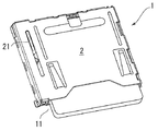
図1は本発明の実施の形態に係るメモリカード用コネクタ1(以下、単に「コネクタ1」ともいう)を示し、所定のメモリーカード(以下、単に「カード」ともいう)に対応している。このカードは、携帯電話などに用いられる小型かつ薄型のメモリーカードであり、そのためこのコネクタ1も当該メモリーカードに合わせて、小型かつ薄型のものである。なお、符号11は、このコネクタ1のメモリーカード挿入用開口である。
FIG. 1 shows a memory card connector 1 (hereinafter also simply referred to as “connector 1”) according to an embodiment of the present invention, and corresponds to a predetermined memory card (hereinafter also simply referred to as “card”). This card is a small and thin memory card used for a cellular phone or the like. Therefore, the connector 1 is also small and thin in accordance with the memory card.
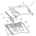
図2に示すように、コネクタ1は、概略、レール溝(カム溝)を有する合成樹脂製のコネクタ本体(ベース)3と、前記レール溝上をスライドするスライダ5と、該スライダ5に取り付けられたバネ部材6と、前記スライダ5をメモリーカード挿入用開口11の方向へ向けて付勢するコイルスプリング(付勢手段)7と、前記スライダ5に回動可能に設けられ、前記ベース3に設けられたレール溝のカム溝と協働してメモリーカードのロックおよびロック解除をするためのガイドピン51と、これらのスライダ5、バネ部材6、コイルスプリング7およびガイドピン51をコネクタ本体3の内部に収納するようにコネクタ本体3を覆う金属製のカバー2と、から構成されている。
As shown in FIG. 2, the connector 1 is roughly a synthetic resin connector body (base) 3 having a rail groove (cam groove), a
なお、このコネクタ本体3には、カードの複数の電極と夫々接触する複数の端子31と、カード挿入完了を検知するためのスイッチ電極32が設けられている。また、本発明では、上記スライダ5、バネ部材6、コイルスプリング7、ガイドピン51およびコネクタ本体3のレール溝のカム溝などで、カードのイジェクト機構を構成する。さらに、図2に示すように、コネクタ本体3のカード挿入用開口11側から見た左側には、コネクタ本体3上に一体に立設された薄板状の取り付けガイドレール4が設けられている。
The
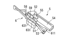
上記バネ部材6は、合成樹脂製のスライダ5に組み込まれ、スライダ5と一体となって図2の矢印で示す方向にスライドするようになっている。このバネ部材6は、図3〜図5に示すように、押さえバネ61と、ハーフロックバネ62と、スライダ取り付け部(基部)63とから構成されており、それらが一体形成されている。押さえバネ61は、後述するスライダ5に回動可能に組み込まれたガイドピン51をコネクタ本体3のレール溝(カム溝)33に押し付けるための板バネである。なお、図2中、符号4は、コネクタ本体3上に一体に立設された薄板状の取り付けガイドレール4を示し、主として、コネクタ1を組み立てる際に、スライダ5を適切な位置に案内するとともに、所定位置に保持(仮止め)しておくために設けられている。
The
このハーフロックバネ62は、図3に示すように、スライダ5に取り付けられる基部63と、該基部63からメモリーカード挿入用開口11の方へ向かって延出する第1の板バネ部626と、第1の板バネ部626の先端に設けられた折り返し部622と、折り返し部622から該折り返し部を頂部として第1の板バネ部626から徐々に離反し該第1の板バネ部626と略V字状をなすように後方へ向かって延出する第2の板バネ部625とを有し、該第2の板バネ部625の先端側にメモリーカードに形成された被係合部に係合するハーフロック用の略V字状の係合部621が設けられている。また、第1の板バネ部626と第2の板バネ部625は、前記折り返し部622において上下にずれた状態で略V字状に広がっている。
As shown in FIG. 3, the
以上のような構造のハーフロックバネ62を有するバネ部材6は、導電性の薄い金属板を所定形状に打ち抜くとともに、それを以上のような構造に曲げ加工することにより形成することができる。
The
なお、本実施形態では、ハーフロックバネ62は、その基部(スライダ取り付け部)63において、スライダ5に取り付けられており、スライダ5が、本発明の「コネクタ内部の被取り付け部」をなしている。すなわち、ハーフロックバネ62の基部63の一対の突起631,631をスライダ5の所定の開口に圧入することにより、バネ部材6がスライダ5に固定されるようになっている。このように基部63は、ハーフロックバネ62と押さえバネ61の共通の圧入部(取り付け部)となっており、圧入部を一つにすることができ、部品を配置するためのスペースを小さくすることが可能となる。
In the present embodiment, the
図4は、スライダ5に組み込まれたバネ部材6を示している。スライダ5のガイドピン51は、押さえバネ61の先端部611により押し付けられている。なお、スライダ5の符号56で示す部分は、図1に示すカバー2のスロット21に案内されるガイド突条である。
FIG. 4 shows the
図5は、図4に示すスライダ5とバネ部材6を裏返した状態を示している。スライダ5の中央に延在する半円筒状の溝54は、コイルスプリング7を収容するためのものである。また、溝54の端部に設けられている突起55は、コイルスプリング7の端部と係合するためのものである。ガイドピン51は、軸52によりスライダ5に取り付けられており、水平方向に回動可能である。また、前述したように、バネ部材6は、基部(スライダ取り付け部)63の突起631、631により、スライダ5に取り付けられている。
FIG. 5 shows a state in which the
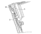
図6は、スライダ5とバネ部材6が、コネクタ本体3に組み込まれた状態を示している。この状態のスライダ5は、コイルスプリング7によって、メモリーカード挿入用開口11側に付勢されている。そして、この状態におけるスライダ5は、スライダ5の取り付けガイド溝58の略角穴状の被係止部59にガイドレール4の係止突起41(図2参照)が係合することにより、保持(仮止め)される。
FIG. 6 shows a state in which the
図7は、本体3のレール溝(カム溝)33を示している。このレール溝33の底面は、スライダ部5に回動可能に組み込まれたガイドピン51の先端部53が所定の方向へと案内されるように、段階的な複数のスロープおよび段部33a〜33fが形成されており、いわゆるハートロックカム機構を構成している。ガイドピン51の先端部53がハーフロック位置から出発してハーフロック位置へ復帰するまでの各スロープ33a〜33f間の高さ関係については、図8に示されている。なお、図7に示す、符号71は、コイルスプリング7をコネクタ本体3に係止するための突起である。
FIG. 7 shows a rail groove (cam groove) 33 of the
このレール溝33をガイドピン51の先端部53がガイドされる様子を、図6、図9ないし図11を用いて説明する。最初に図6の状態において、カード挿入用開口11からカードが挿入されると、カード側方の凹部12(図9参照)にハーフロックバネ62の係合部621が係合する。この状態がハーフロック状態であり、カードが軽く保持される。なお、図9は、このハーフロック状態から、カードがコネクタ1内に押しこまれた状態を示している。
The manner in which the
さらにカードをコネクタ1に挿入してゆくと、スライダ5の斜面57がカードの傾斜部13と当接し(図9参照)、コイルスプリング7を押し縮めながらスライダ部5が挿入方向に移動してゆく。このとき、ガイドピン51の先端部53がレール溝33のスロープ33bを登ってゆく状態を示したのが図9である。
When the card is further inserted into the connector 1, the
図10は、カードをコネクタ1に完全に押し込んだ状態を示している。ここで、ガイドピン51の先端部53は、レール溝33の段部33cに落とし込まれる。このため、先端部53はスロープ33bに戻ることはできない。そして、カードの押し込み止めると、コイルスプリング7の付勢力により、スライダ5はメモリーカード挿入用開口11側へ押し戻され、ガイドピン51の先端部は段部33dに移動し、その凹部34に係合する。この状態がカード挿入完了状態(ロック状態)である。
FIG. 10 shows a state in which the card is completely pushed into the connector 1. Here, the
ロック状態を解除してカードを取り外す場合には、カードをカード挿入完了状態からさらに奥に向けてコネクタ1へ押し込む。ガイドピン51の先端部53は、図11に示すように、段部33e(図7及び図8参照)へ進出し、上記凹部34から離脱する。そして、図12に示すように、コイルスプリング7の付勢力により、スロープ33fを経てハーフロック位置、すなわち、図6に示す位置まで復帰する。この際、スライダ5の取り付けガイド溝58の略角穴状の被係止部59にガイドレール4の係止突起41(図2)が係合することにより、スライダ5の後退が制限され、その状態で保持(仮止めされる)。この復帰したハーフロック位置において、カードはコネクタ1に軽く支持されている。
When releasing the locked state and removing the card, the card is pushed into the connector 1 from the card insertion completion state to the back. As shown in FIG. 11, the
以下、本実施例の作用効果を説明する。
図6に示すハーフロック位置の状態において、カードを挿入すると、ハーフロックバネ62の係合部621が十分なストロークと反発力で変形しかつ復元してカードの凹部12に係合し、カードをハーフロック状態で確実に保持する。すなわち、このハーフロックバネ62は、全体が略V字状に折返された形状の板バネとなっており、そのため全長は短くても十分な反発力とストローク量を提供できる十分なバネ長を確保している。そのため、コネクタの小型化に貢献できる。
Hereinafter, the function and effect of the present embodiment will be described.
When the card is inserted in the half-locked position shown in FIG. 6, the engaging
また、ハーフロックバネ62と押さえバネ61が一体に形成されたバネ部材6を用いているので、部品点数を削減でき、また組み付け工程も減らすことが可能となる。この場合、このハーフロックバネ62と押さえバネ61は、共通の取り付け部であるハーフロックバネの基部(スライダ取り付け部)63に突起631,631をスライダ5に圧入することによりスライダに固定されているので、圧入部を一箇所にでき、部品を配置するスペースを小さくできる。
Further, since the
以上、本発明の好適実施形態について説明したが、本発明が以上の実施形態に限定されるものではなく、種々の改良や改変が可能なことは言うまでもない。 As mentioned above, although preferred embodiment of this invention was described, it cannot be overemphasized that this invention is not limited to the above embodiment, and various improvement and a change are possible.
たとえば、上記実施形態では、ハーフロックバネ62とガイドピンの押さえバネ61を一体に形成したバネ部材6を用いるとともに、そのようなバネ部材6をイジェクト機構を構成するスライダに取り付けた構成としたが、以上の構造のハーフロックバネ62を押さえバネ61とは別体に構成し、そのようなハーフロックバネをコネクタ本体3に独立して固定的に設けるようにしてもよい。そのような構成にした場合でも、全長は短くても十分な反発力とストローク量を提供できる十分なバネ長を有するハーフロックバネを備えることができ、コネクタの小型化を実現できる。なお、このような構造の場合、コネクタ本体3のハーフロックバネの取り付け部が本発明の「コネクタ内部の被取り付け部」をなすことになる。
For example, in the above-described embodiment, the
また、本発明のハーフロックバネの構造は、ハーフロック機構が必要なものであれば、上記実施形態にかかるメモリーカード以外の各種メモリーカード用のコネクタに適用することができる。 Further, the structure of the half lock spring of the present invention can be applied to connectors for various memory cards other than the memory card according to the embodiment as long as a half lock mechanism is required.
1 メモリーカード用コネクタ
2 カバー
3 コネクタ本体
4 ガイドレール
5 スライダ
6 バネ部材
7 コイルスプリング(付勢手段)
11 メモリーカード挿入用開口
12 凹部
13 傾斜部
21 スロット
31 端子
32 スイッチ電極
33 レール溝(カム溝)
33a〜33f スロープおよび段部
34 凹部
41 係止突起
51 ガイドピン
52 軸
53 ピン先端部
54 溝
55 突起
56 ガイド突条
57 斜面
58 取り付けガイド溝
59 被係止部
61 押さえバネ
62 ハーフロックバネ
621 係合部
622 折り返し部
625 第2の板バネ部
626 第1の板バネ部
63 基部(スライダ取り付け部)
631 突起
71 突起
DESCRIPTION OF SYMBOLS 1
11 Memory
33a to 33f Slope and step 34
631
Claims (4)
And a pressing spring that biases the guide pin toward the cam groove, and the base of the half-lock spring extends so that the pressing spring extends substantially opposite to the half-lock spring across the slider. 4. The memory card connector according to claim 3, wherein the memory card connector is formed integrally with the connector.
Priority Applications (1)
| Application Number | Priority Date | Filing Date | Title |
|---|---|---|---|
| JP2004108271A JP2005294075A (en) | 2004-03-31 | 2004-03-31 | Memory card connector |
Applications Claiming Priority (1)
| Application Number | Priority Date | Filing Date | Title |
|---|---|---|---|
| JP2004108271A JP2005294075A (en) | 2004-03-31 | 2004-03-31 | Memory card connector |
Publications (1)
| Publication Number | Publication Date |
|---|---|
| JP2005294075A true JP2005294075A (en) | 2005-10-20 |
Family
ID=35326768
Family Applications (1)
| Application Number | Title | Priority Date | Filing Date |
|---|---|---|---|
| JP2004108271A Pending JP2005294075A (en) | 2004-03-31 | 2004-03-31 | Memory card connector |
Country Status (1)
| Country | Link |
|---|---|
| JP (1) | JP2005294075A (en) |
-
2004
- 2004-03-31 JP JP2004108271A patent/JP2005294075A/en active Pending
Similar Documents
| Publication | Publication Date | Title |
|---|---|---|
| JP3818256B2 (en) | Memory card connector device | |
| US7182645B2 (en) | Card connector for an electronic device and a contact used therein | |
| US6210193B1 (en) | Card reader connector | |
| US6881086B2 (en) | Card connector | |
| KR100865610B1 (en) | Connector for card | |
| US7447522B2 (en) | Card holding structure for cellular phone | |
| US6840786B2 (en) | Card connector having improved support member for eject mechanism | |
| US6554627B1 (en) | Electronic card connector and method for assembling same | |
| CN101447613A (en) | Card connector capable of switching a card holding state with a simple structure | |
| JP2006318216A (en) | Memory card socket | |
| US7014508B2 (en) | Multi-card connector assembly with a movable multi-card connector | |
| JP2007234472A (en) | Card connector | |
| JP4023389B2 (en) | Memory card socket | |
| JP4109669B2 (en) | Card connector | |
| JP3935830B2 (en) | Card connector | |
| JP2005294075A (en) | Memory card connector | |
| JP2005294076A (en) | Memory card connector with eject mechanism | |
| US7179104B2 (en) | Connector which can be reduced in size | |
| JP4502699B2 (en) | Card connector | |
| JP4079867B2 (en) | Card connector | |
| JP3885286B2 (en) | Push switch | |
| JP4414398B2 (en) | Electric socket device for card | |
| JP4406349B2 (en) | Card connector | |
| JP2004362892A (en) | Socket for memory card | |
| JP2004335173A (en) | IC card connector |