JP2005294047A - Safety switch - Google Patents
Safety switch Download PDFInfo
- Publication number
- JP2005294047A JP2005294047A JP2004107716A JP2004107716A JP2005294047A JP 2005294047 A JP2005294047 A JP 2005294047A JP 2004107716 A JP2004107716 A JP 2004107716A JP 2004107716 A JP2004107716 A JP 2004107716A JP 2005294047 A JP2005294047 A JP 2005294047A
- Authority
- JP
- Japan
- Prior art keywords
- switch
- operation unit
- rod
- actuator
- outside
- Prior art date
- Legal status (The legal status is an assumption and is not a legal conclusion. Google has not performed a legal analysis and makes no representation as to the accuracy of the status listed.)
- Granted
Links
- 238000003780 insertion Methods 0.000 claims abstract description 16
- 230000037431 insertion Effects 0.000 claims abstract description 16
- 230000005284 excitation Effects 0.000 description 2
- 230000005856 abnormality Effects 0.000 description 1
- 230000000881 depressing effect Effects 0.000 description 1
- 238000012423 maintenance Methods 0.000 description 1
- 230000002093 peripheral effect Effects 0.000 description 1
Images
Landscapes
- Mechanisms For Operating Contacts (AREA)
Abstract
Description
本発明は、産業用ロボットや工作機械などの機械への出入口などに設置される安全スイッチに関する。 The present invention relates to a safety switch installed at an entrance to an industrial robot or machine tool.
従来の安全スイッチとしては特許文献1がある。
There exists
この特許文献1に開示のような安全スイッチは、出入口の扉にアクチュエータが取り付けられており、扉を閉めると、このアクチュエータ(操作キーや鍵とも称される)が安全スイッチに挿入され、アクチュエータの挿入その他の動作に対応して内蔵の操作ロッドが移動し、操作ロッドが内蔵のスイッチを押し下げてオフあるいはオンする構成になっている。
In the safety switch as disclosed in
従来の安全スイッチは操作ロッドでスイッチを押し下げるという考え方なので、安全スイッチの細かな動作、すなわち操作ロッドの様々な移動箇所を検出する場合、多数のスイッチが必要になり、構成が複雑になるという問題点があった。 The conventional safety switch is based on the concept that the switch is pushed down by the operating rod. Therefore, when detecting the detailed movement of the safety switch, that is, when various moving parts of the operating rod are detected, a large number of switches are required and the configuration is complicated. There was a point.
本発明は上記の問題点を解決するためになされたものであり、様々な動作状態を検出することが可能で、しかも構成が簡単な安全スイッチを得ることを目的とする。 The present invention has been made to solve the above problems, and an object of the present invention is to obtain a safety switch that can detect various operating states and has a simple configuration.
請求項1に記載の課題解決手段において、所定方向に移動可能で、側面に複数の段差のある移動体と、外部からアクチュエータが抜差しされ、当該アクチュエータの抜差しに応じて前記移動体を移動させる第1の操作部と、前記移動体の側面に沿って進退することでオンあるいはオフする複数のスイッチとを備えた安全スイッチ。
The problem-solving means according to
請求項2に記載の課題解決手段において、前記第1の操作部が前記移動体を移動させることができる範囲外に前記移動体を移動させることが可能な第2の操作部をさらに備え、前記複数の段差のうち少なくとも1つは、前記移動体が前記範囲外に移動しているときに、前記スイッチをオンあるいはオフさせる。
The problem solving means according to
請求項3に記載の課題解決手段において、前記範囲外には、前記第1の操作部内の所定領域を含み、前記第2の操作部は前記移動体を前記第1の操作部の所定領域に差し込むことで、前記第1の操作部の動作を固定する。
The problem-solving means according to
請求項4に記載の課題解決手段において、前記移動体及び前記複数のスイッチを内蔵し、前記第1の操作部に取り付けられる筐体をさらに備え、前記範囲外には、前記筐体外の所定領域を含み、前記第1の操作部が前記筐体から外れると、前記第2の操作部は前記移動体を前記筐体外の所定領域へ移動させる。
The problem solving means according to
請求項1に記載の発明によれば、複数のスイッチは移動体の側面に沿って進退することでオンあるいはオフするので、移動体の様々な移動位置、つまり、様々な動作状態を検出することが可能で、しかも構成が簡単である。 According to the first aspect of the present invention, since the plurality of switches are turned on or off by moving back and forth along the side surface of the moving body, various moving positions of the moving body, that is, various operating states can be detected. Is possible, and the configuration is simple.
請求項2に記載の発明によれば、第2の操作部の作用による移動体の移動を検出することができる。 According to the second aspect of the present invention, it is possible to detect the movement of the moving body due to the action of the second operation unit.
請求項3に記載の発明によれば、第2の操作部によって第1の操作部の動作が固定されたことを検出することができる。 According to the third aspect of the present invention, it can be detected that the operation of the first operation unit is fixed by the second operation unit.
請求項4に記載の発明によれば、筐体から第1の操作部が外れたことを検出することができる。
According to invention of
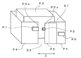
本発明の実施の形態の安全スイッチは例えば図5に示すようなシステムに適用される。安全柵P4は部屋S1を囲み、部屋S1内には機械P3が設置されている。安全柵P4には出入口S2が設けられ、出入口S2を通ってオペレータや搬送物が外部と部屋S1との間を出入りできる。また、安全柵P4には出入口S2を閉じるための扉P5が設けられている。扉P5は方向Zに移動できる。安全柵P4の端部P4a付近には安全スイッチP1が設けられ、扉P5の端部P5a付近にはアクチュエータP2が設けられている。 The safety switch according to the embodiment of the present invention is applied to a system as shown in FIG. 5, for example. The safety fence P4 surrounds the room S1, and a machine P3 is installed in the room S1. The safety fence P4 is provided with an entrance S2, and an operator and a transported object can enter and exit between the outside and the room S1 through the entrance S2. The safety fence P4 is provided with a door P5 for closing the entrance S2. The door P5 can move in the direction Z. A safety switch P1 is provided near the end P4a of the safety fence P4, and an actuator P2 is provided near the end P5a of the door P5.
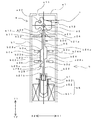
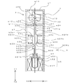
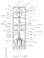
図1〜図3は本発明の実施の形態における安全スイッチの内部構造図である。本実施の形態における安全スイッチは図5の安全スイッチP1に対応し、図1〜図3のアクチュエータcは図5のアクチュエータP2に対応している。 1 to 3 are internal structural views of the safety switch according to the embodiment of the present invention. The safety switch in the present embodiment corresponds to the safety switch P1 in FIG. 5, and the actuator c in FIGS. 1 to 3 corresponds to the actuator P2 in FIG.
本実施の形態の安全スイッチは、操作ヘッドaとスイッチ本体bとを含んで構成される。なお、図ではスイッチ本体b下方を省略している。操作ヘッドaは外部からアクチュエータcが差し込まれることによって、外部からの操作力を受け、この操作力をスイッチ本体bへ伝える機能を有する。スイッチ本体bは操作ヘッドaから伝えられた操作力を受け、この操作力に基づいてオンあるいはオフする機能と、操作ヘッドaの動作を固定(ロック)する機能とを有する。 The safety switch according to the present embodiment includes an operation head a and a switch body b. In the figure, the lower part of the switch body b is omitted. The operating head a has a function of receiving an operating force from the outside when the actuator c is inserted from the outside and transmitting the operating force to the switch body b. The switch body b has an operation force received from the operation head a and has a function of turning on or off based on the operation force and a function of fixing (locking) the operation of the operation head a.
まず、操作ヘッドaの構成について説明する。操作ヘッドaは筐体a1と偏心カムa2とを含んで構成される。筐体a1は内部に偏心カムa2を収納する略立方体形状であり、上面、下面、一つの側面にそれぞれに挿入孔a11、開口部a12、挿入孔a13が設けられている。側面の挿入孔a13は図1などに示すように、外部からのアクチュエータcが差し込まれるためのものである。また、上面にもアクチュエータcが差し込むことができるように、挿入孔a11が設けられている。 First, the configuration of the operation head a will be described. The operation head a includes a housing a1 and an eccentric cam a2. The housing a1 has a substantially cubic shape for accommodating the eccentric cam a2 therein, and an upper surface, a lower surface, and one side surface are provided with an insertion hole a11, an opening a12, and an insertion hole a13, respectively. The side insertion hole a13 is for inserting an actuator c from the outside, as shown in FIG. Also, an insertion hole a11 is provided on the upper surface so that the actuator c can be inserted.
偏心カムa2は筐体a1の内部において、挿入孔a11のある上面と挿入孔a13のある側面との法線方向の中心軸a21を中心に回動可能に保持されている。偏心カムa2の外周の表面には、凹部a22、凹部a23、凹部a24が設けられている。凹部a22は挿入孔a13から挿入されたアクチュエータcの先端部を引っかけるために設けられている。凹部a23は挿入孔a11から挿入されたアクチュエータcの先端部が引っかけるために設けられている。凹部a24は後述の操作ロッド(移動体)b2が差し込まれて操作ヘッドaの偏心カムa2の回動動作をロックするために設けられている。 The eccentric cam a2 is held inside the housing a1 so as to be rotatable about a central axis a21 in the normal direction between the upper surface with the insertion hole a11 and the side surface with the insertion hole a13. A concave portion a22, a concave portion a23, and a concave portion a24 are provided on the outer peripheral surface of the eccentric cam a2. The recess a22 is provided to hook the tip of the actuator c inserted from the insertion hole a13. The recess a23 is provided to catch the tip of the actuator c inserted from the insertion hole a11. The recess a24 is provided to lock an operation of the eccentric cam a2 of the operation head a by inserting an operation rod (moving body) b2 described later.
次にスイッチ本体bの構成について説明する。スイッチ本体bは筐体b1、操作ロッドb2、スイッチb3a、スイッチb3b、スイッチb3c、スイッチb3d、付勢手段b4及びロック部(第2の操作部)b5を含んで構成されている。 Next, the configuration of the switch body b will be described. The switch body b includes a housing b1, an operation rod b2, a switch b3a, a switch b3b, a switch b3c, a switch b3d, an urging means b4, and a lock part (second operation part) b5.
筐体b1は内部に操作ロッドb2、スイッチb3a、スイッチb3b、スイッチb3c、スイッチb3d、付勢手段b4及びロック部b5を収納する略四角柱状である。筐体b1の上面には操作ロッドb2の先端が突出するための開口部b11が設けられている。この筐体b1の上面と操作ヘッドaの開口部a12のある下面とが対向するように、操作ヘッドaがスイッチ本体bに取り付けられる。 The housing b1 has a substantially quadrangular prism shape that houses the operation rod b2, the switch b3a, the switch b3b, the switch b3c, the switch b3d, the urging means b4, and the lock portion b5. An opening b11 through which the tip of the operation rod b2 protrudes is provided on the upper surface of the housing b1. The operation head a is attached to the switch body b so that the upper surface of the housing b1 and the lower surface with the opening a12 of the operation head a face each other.
操作ロッドb2は細長い棒状であり、方向Y1、その逆の方向Y2に移動可能に筐体b1内に保持されている。操作ロッドb2の側面には基準表面b22に対して突出する台形状凸部b23、台形状凸部b24、台形状凸部b25が設けられている。台形状凸部b23、台形状凸部b24はそれぞれ基準表面b22に対して外側に突出した台形状である。つまり、台形状凸部b23、台形状凸部b24、台形状凸部b25それぞれにおける操作ロッドb2の側面は基準表面b22から台形状凸部b23、台形状凸部b24、台形状凸部b25の傾斜部b23a、傾斜部b24a、傾斜部b25aに沿って突出して頂部b23b、頂部b24b、頂部b25bに達し、この頂部から傾斜部b23c、傾斜部b24cに沿って基準表面b22に達する。 The operation rod b2 has a long and narrow bar shape, and is held in the housing b1 so as to be movable in the direction Y1 and in the opposite direction Y2. A trapezoidal convex part b23, a trapezoidal convex part b24, and a trapezoidal convex part b25 projecting with respect to the reference surface b22 are provided on the side surface of the operation rod b2. Each of the trapezoidal convex part b23 and the trapezoidal convex part b24 has a trapezoidal shape protruding outward with respect to the reference surface b22. That is, the side surfaces of the operation rod b2 in each of the trapezoidal convex part b23, the trapezoidal convex part b24, and the trapezoidal convex part b25 are inclined from the reference surface b22 to the trapezoidal convex part b23, the trapezoidal convex part b24, and the trapezoidal convex part b25. It protrudes along the part b23a, the inclined part b24a, and the inclined part b25a and reaches the top part b23b, the top part b24b, and the top part b25b, and reaches the reference surface b22 along the inclined part b23c and the inclined part b24c.
操作ロッドb2の側面の近傍には、スイッチb3a、スイッチb3b、スイッチb3c、スイッチb3dが配置されている。スイッチb3a、スイッチb3b、スイッチb3c、スイッチb3dのそれぞれは進退部b3eが設けられている。この進退部b3eは、方向Y1、方向Y2と交わる方向の方向X1、その逆の方向X2(ここでは方向Y1、方向Y2と方向X1、方向X2とは互いに直角方向)に進退し、進退部b3eの先端は操作ロッドb2の側面に対向する。 A switch b3a, a switch b3b, a switch b3c, and a switch b3d are disposed in the vicinity of the side surface of the operation rod b2. Each of the switch b3a, the switch b3b, the switch b3c, and the switch b3d is provided with an advance / retreat portion b3e. The advancing / retreating portion b3e advances / retreats in the direction Y1, the direction X1 intersecting the direction Y2, and the opposite direction X2 (here, the direction Y1, the direction Y2, the direction X1, and the direction X2 are perpendicular to each other), and the advancing / retreating portion b3e. The tip of the is opposed to the side surface of the operating rod b2.
操作ロッドb2の他端部b21bには操作ロッドb2を方向Y1へ常に付勢する付勢手段b4が設けられている。付勢手段b4は付勢力を付勢手段b4へ与えられるものであればよく、図示のようなコイルバネの他、板バネなどでもよい。 The other end b21b of the operating rod b2 is provided with a biasing means b4 that constantly biases the operating rod b2 in the direction Y1. The urging means b4 is not limited as long as it can apply an urging force to the urging means b4, and may be a plate spring or the like in addition to the coil spring as shown.
また、操作ロッドb2の他端部b21bには操作ロッドb2を偏心カムa2の凹部a24に差し込むことで、操作ヘッドaの動作をロックするためのロック部b5が設けられている。ロック部b5はソレノイドb51と保持部b52と付勢手段b53とを含んで構成されている。保持部b52は操作ロッドb2を方向Y1、方向Y2に移動可能に保持し、付勢手段b4は保持部b52から操作ロッドb2を引き離すように操作ロッドb2に付勢力を与える。ソレノイドb51は電流が流れて励磁されると、保持部b52を方向Y2へ引き込み、これによって、操作ロッドb2を偏心カムa2の凹部a24から外し、操作ヘッドaの動作のロックを解除する。付勢手段53は図示のようにコイルバネの他、板バネで構成してもよい。付勢手段b53の付勢力はソレノイドb51が保持部b52を引き込む力と比較して弱く、ソレノイドb51に電流が流れず励磁が止むと、付勢手段b53はソレノイドb51から保持部b52を引き離すように保持部b52に付勢力を与え、これによって、操作ロッドb2が偏心カムa2の凹部a24に差し込まれ、操作ヘッドaの動作がロックされる。 The other end b21b of the operation rod b2 is provided with a lock portion b5 for locking the operation of the operation head a by inserting the operation rod b2 into the recess a24 of the eccentric cam a2. The lock part b5 includes a solenoid b51, a holding part b52, and an urging means b53. The holding part b52 holds the operating rod b2 so as to be movable in the directions Y1 and Y2, and the biasing means b4 applies a biasing force to the operating rod b2 so as to pull the operating rod b2 away from the holding part b52. When the solenoid b51 is excited by a current flowing, it pulls the holding part b52 in the direction Y2, thereby removing the operation rod b2 from the recess a24 of the eccentric cam a2 and unlocking the operation of the operation head a. The biasing means 53 may be constituted by a plate spring in addition to a coil spring as shown in the figure. The urging force of the urging means b53 is weaker than the force with which the solenoid b51 pulls the holding part b52, and when the excitation stops without current flowing through the solenoid b51, the urging means b53 pulls the holding part b52 away from the solenoid b51. A biasing force is applied to the holding part b52, whereby the operation rod b2 is inserted into the concave part a24 of the eccentric cam a2, and the operation of the operation head a is locked.
次に安全スイッチの動作について説明する。まず、図3において、扉P5(図5参照)が開いており、アクチュエータcが安全スイッチの操作ヘッドaに差し込まれておらず、また、ソレノイドb51は励磁されており、保持部b52を方向Y2に引き込んでおり、操作ロッドb2は偏心カムa2に押されて、方向Y2へ後退している。この状態では、スイッチb3aの進退部b3eは操作ロッドb2の表面に押されておらず前進し、スイッチb3aはオンの状態である。スイッチb3aがオンであることは操作ヘッドaの偏心カムa2の回動動作がロックされていないことを示す。スイッチb3bの進退部b3eは操作ロッドb2の台形状凸部b23の頂部b23bに押されて後退し、スイッチb3bはオフの状態である。スイッチb3cの進退部b3eは操作ロッドb2の表面に押されておらず前進し、スイッチb3cはオンの状態である。スイッチb3cがオンであることは扉P5が開いていることを示す。スイッチb3dの進退部b3eは操作ロッドb2の台形状凸部b24の頂部b24bに押されて後退し、スイッチb3dはオフの状態である。 Next, the operation of the safety switch will be described. First, in FIG. 3, the door P5 (see FIG. 5) is open, the actuator c is not inserted into the operation head a of the safety switch, the solenoid b51 is excited, and the holding portion b52 is moved in the direction Y2. The operating rod b2 is pushed by the eccentric cam a2 and retracted in the direction Y2. In this state, the advance / retreat portion b3e of the switch b3a moves forward without being pushed by the surface of the operation rod b2, and the switch b3a is in an on state. The fact that the switch b3a is on indicates that the rotation operation of the eccentric cam a2 of the operation head a is not locked. The forward / backward part b3e of the switch b3b is pushed back by the top part b23b of the trapezoidal convex part b23 of the operating rod b2, and the switch b3b is in an OFF state. The forward / backward portion b3e of the switch b3c moves forward without being pushed by the surface of the operation rod b2, and the switch b3c is in an ON state. The switch b3c being on indicates that the door P5 is open. The forward / backward part b3e of the switch b3d is pushed back by the top part b24b of the trapezoidal convex part b24 of the operating rod b2, and the switch b3d is in an OFF state.
コントローラP6はスイッチb3aのオン、スイッチb3bのオフ、スイッチb3cのオン、スイッチb3dのオフを受け、機械P3の動作を許可しない。 The controller P6 receives the ON state of the switch b3a, the OFF state of the switch b3b, the ON state of the switch b3c, and the OFF state of the switch b3d, and does not permit the operation of the machine P3.
次に、扉P5を閉じると、操作ヘッドaの挿入孔a13にアクチュエータcが差し込まれる。アクチュエータcの先端は凹部a22に係合し、アクチュエータcが操作ヘッドa内のさらに奥へ差し込まれることにより、偏心カムa2は中心軸a21を中心に回動する。この偏心カムa2の回動に伴い、付勢手段b4によって方向Y1へ付勢力が与えられている操作ロッドb2は一端部b21aが偏心カムa2の外縁に接して動く。そして、アクチュエータcが完全に操作ヘッドa内に差し込まれ、操作ヘッドaの凹部a24が操作ロッドb2の一端部b21aに対向するところに位置する。操作ロッドb2は付勢手段b4の付勢力によって方向Y1へ移動しようとするが、保持部b52によって移動が規制される。この操作ロッドb2の移動により、スイッチb3cの進退部b3eは操作ロッドb2の基準表面b22から台形状凸部b24の傾斜部b24aに沿って押されて後退し、進退部b3eが頂部b24bに達したとき、スイッチb3cはオフになる。スイッチb3dの進退部b3eは操作ロッドb2の台形状凸部b24の頂部b24bから傾斜部b24cに沿って前進し、進退部b3eが基準表面b22に対向する位置に達したとき、スイッチb3dはオンになる。スイッチb3dがオンであることは扉P5が閉じていることを示す。スイッチb3a、スイッチb3bについてはそれぞれオン、オフの状態のままである(図2)。 Next, when the door P5 is closed, the actuator c is inserted into the insertion hole a13 of the operation head a. The tip of the actuator c engages with the recess a22, and the actuator c is inserted further into the operation head a, whereby the eccentric cam a2 rotates about the central axis a21. As the eccentric cam a2 rotates, the operation rod b2 to which the urging force is applied in the direction Y1 by the urging means b4 moves with its one end b21a in contact with the outer edge of the eccentric cam a2. The actuator c is completely inserted into the operation head a, and the concave portion a24 of the operation head a is positioned so as to face the one end b21a of the operation rod b2. The operating rod b2 tries to move in the direction Y1 by the urging force of the urging means b4, but the movement is restricted by the holding portion b52. By this movement of the operating rod b2, the advance / retreat portion b3e of the switch b3c is pushed back from the reference surface b22 of the operation rod b2 along the inclined portion b24a of the trapezoidal convex portion b24, and the advance / retreat portion b3e reaches the top portion b24b. When switch b3c is turned off. The advance / retreat portion b3e of the switch b3d advances from the top b24b of the trapezoidal convex portion b24 of the operation rod b2 along the inclined portion b24c, and when the advance / retreat portion b3e reaches a position facing the reference surface b22, the switch b3d is turned on. Become. The switch b3d being on indicates that the door P5 is closed. The switches b3a and b3b remain on and off, respectively (FIG. 2).
コントローラP6はスイッチb3aのオン、スイッチb3bのオフ、スイッチb3cのオフ、スイッチb3dのオンを受け、機械P3の動作を許可しない。 The controller P6 receives the ON state of the switch b3a, the OFF state of the switch b3b, the OFF state of the switch b3c, and the ON state of the switch b3d, and does not permit the operation of the machine P3.
次に、ソレノイドb51に電流を流すことを止めてソレノイドb51の励磁が止むと、ソレノイドb51から保持部b52を引き離す付勢手段b53の付勢力により、操作ロッドb2は方向Y1へ移動し、操作ロッドb2の一端部b21aは偏心カムa2の凹部a24に差し込まれる。これによって、回動しないように偏心カムa2の動作はロックされ、アクチュエータcを操作ヘッドaから引き抜くことができない。また、操作ロッドb2の移動により、スイッチb3aの進退部b3eは操作ロッドb2の基準表面b22から台形状凸部b23の傾斜部b23aに沿って押されて後退し、進退部b3eが頂部b23bに達したとき、スイッチb3aはオフになる。スイッチb3bの進退部b3eは操作ロッドb2の台形状凸部b23の頂部b23bから傾斜部b23cに沿って前進し、進退部b3eが基準表面b22に対向する位置に達したとき、スイッチb3bはオンになる。スイッチb3bがオンであることは操作ヘッドaの偏心カムa2の回動動作がロックされていることを示す。スイッチb3c、スイッチb3dについてはそれぞれオフ、オンの状態のままである(図1)。 Next, when the current flow to the solenoid b51 is stopped and the excitation of the solenoid b51 is stopped, the operation rod b2 moves in the direction Y1 by the urging force of the urging means b53 that separates the holding portion b52 from the solenoid b51, and the operation rod One end b21a of b2 is inserted into the recess a24 of the eccentric cam a2. As a result, the operation of the eccentric cam a2 is locked so as not to rotate, and the actuator c cannot be pulled out from the operation head a. Further, by the movement of the operation rod b2, the advance / retreat portion b3e of the switch b3a is pushed back from the reference surface b22 of the operation rod b2 along the inclined portion b23a of the trapezoidal convex portion b23, and the advance / retreat portion b3e reaches the top portion b23b. When this occurs, the switch b3a is turned off. The advance / retreat portion b3e of the switch b3b advances from the top b23b of the trapezoidal convex portion b23 of the operation rod b2 along the inclined portion b23c, and when the advance / retreat portion b3e reaches a position facing the reference surface b22, the switch b3b is turned on. Become. The fact that the switch b3b is on indicates that the rotation operation of the eccentric cam a2 of the operation head a is locked. The switches b3c and b3d remain off and on, respectively (FIG. 1).
コントローラP6はスイッチb3aのオフ、スイッチb3bのオン、スイッチb3cのオフ、スイッチb3dのオンを受け、機械P3の動作を許す。 The controller P6 receives the turn-off of the switch b3a, the turn-on of the switch b3b, the turn-off of the switch b3c, and the turn-on of the switch b3d, and permits the operation of the machine P3.
扉P5を開く場合は、上述と逆の動作である。すなわち、まず、図1において、扉P5が閉じており、アクチュエータcが安全スイッチの操作ヘッドaに差し込まれ、ソレノイドb51は励磁されていない状態である。操作ロッドb2の一端部b21aは偏心カムa2の凹部a24に差し込まれている。これによって、回動しないように偏心カムa2の動作はロックされ、アクチュエータcを操作ヘッドaから引き抜くことができない。この状態では、スイッチb3aの進退部b3eは操作ロッドb2の台形状凸部b23の頂部b23bに押されて後退し、スイッチb3aはオフの状態である。スイッチb3bの進退部b3eは操作ロッドb2の表面に押されておらず前進し、スイッチb3bはオンの状態である。スイッチb3bがオンであることは操作ヘッドaの偏心カムa2の回動動作がロックされていることを示す。スイッチb3cの進退部b3eは操作ロッドb2の台形状凸部b24の頂部b24bに押されて後退し、スイッチb3cはオフの状態である。スイッチb3dの進退部b3eは操作ロッドb2の表面に押されておらず前進し、スイッチb3dはオンの状態である。スイッチb3dがオンであることは扉P5が閉じていることを示す。 When the door P5 is opened, the operation is the reverse of the above. That is, first, in FIG. 1, the door P5 is closed, the actuator c is inserted into the operation head a of the safety switch, and the solenoid b51 is not excited. One end b21a of the operation rod b2 is inserted into the recess a24 of the eccentric cam a2. As a result, the operation of the eccentric cam a2 is locked so as not to rotate, and the actuator c cannot be pulled out from the operation head a. In this state, the forward / backward portion b3e of the switch b3a is pushed back by the top portion b23b of the trapezoidal convex portion b23 of the operation rod b2, and the switch b3a is in an off state. The forward / backward portion b3e of the switch b3b moves forward without being pushed by the surface of the operation rod b2, and the switch b3b is in an ON state. The fact that the switch b3b is on indicates that the rotation operation of the eccentric cam a2 of the operation head a is locked. The forward / backward part b3e of the switch b3c is pushed back by the top part b24b of the trapezoidal convex part b24 of the operating rod b2, and the switch b3c is in an OFF state. The forward / backward portion b3e of the switch b3d moves forward without being pushed by the surface of the operation rod b2, and the switch b3d is in an on state. The switch b3d being on indicates that the door P5 is closed.
コントローラP6はスイッチb3aのオフ、スイッチb3bのオン、スイッチb3cのオフ、スイッチb3dのオンを受け、機械P3の動作を許す。 The controller P6 receives the turn-off of the switch b3a, the turn-on of the switch b3b, the turn-off of the switch b3c, and the turn-on of the switch b3d, and permits the operation of the machine P3.
次に、ソレノイドb51を励磁して、保持部b52をソレノイドb51が引き込み、操作ロッドb2を方向Y2へ移動させることで、操作ロッドb2の一端部b21aは偏心カムa2の凹部a24から引き抜かれる。これによって、偏心カムa2の動作のロックは解除される。また、操作ロッドb2の移動により、スイッチb3aの進退部b3eは操作ロッドb2の頂部b23bから台形状凸部b23の傾斜部b23aに沿って前進し、進退部b3eが基準表面b22に達したとき、スイッチb3aはオンになる。スイッチb3aがオンであることは操作ヘッドaの偏心カムa2の回動動作がロックされていないことを示す。スイッチb3bの進退部b3eは操作ロッドb2の基準表面b22から傾斜部b23cに沿って押されて後退し、進退部b3eが頂部b23bに達したとき、スイッチb3bはオフになる。スイッチb3c、スイッチb3dについてはそれぞれオフ、オンの状態のままである(図2)。 Next, the solenoid b51 is excited, the holding part b52 is pulled by the solenoid b51, and the operating rod b2 is moved in the direction Y2, whereby the one end b21a of the operating rod b2 is pulled out from the recess a24 of the eccentric cam a2. Thereby, the operation lock of the eccentric cam a2 is released. Further, when the operation rod b2 moves, the advance / retreat portion b3e of the switch b3a advances from the top portion b23b of the operation rod b2 along the inclined portion b23a of the trapezoidal convex portion b23, and when the advance / retreat portion b3e reaches the reference surface b22, The switch b3a is turned on. The fact that the switch b3a is on indicates that the rotation operation of the eccentric cam a2 of the operation head a is not locked. The forward / backward portion b3e of the switch b3b is pushed back from the reference surface b22 of the operating rod b2 along the inclined portion b23c, and when the forward / backward portion b3e reaches the top portion b23b, the switch b3b is turned off. The switches b3c and b3d remain off and on (FIG. 2).
コントローラP6はスイッチb3aのオン、スイッチb3bのオフ、スイッチb3cのオフ、スイッチb3dのオンを受け、機械P3の動作を許可しない。 The controller P6 receives the ON state of the switch b3a, the OFF state of the switch b3b, the OFF state of the switch b3c, and the ON state of the switch b3d, and does not permit the operation of the machine P3.
次に、扉P5を開くと、操作ヘッドaの挿入孔a13からアクチュエータcが引き抜かれる。これに伴い、偏心カムa2は中心軸a21を中心に回動する。この偏心カムa2の回動に伴い、操作ロッドb2は一端部b21aが偏心カムa2の外周に接しながら方向Y2へ動く。そして、アクチュエータcが完全に操作ヘッドaから引き抜かれる。この操作ロッドb2の移動により、スイッチb3cの進退部b3eは操作ロッドb2の頂部b24bから台形状凸部b24の傾斜部b24aに沿って前進し、進退部b3eが基準表面b22に達したとき、スイッチb3cはオンになる。スイッチb3cがオンであることは扉P5が開いていることを示す。スイッチb3dの進退部b3eは操作ロッドb2の基準表面b22から傾斜部b24cに沿って押されて後退し、進退部b3eが頂部b24bに達したとき、スイッチb3dはオフになる。スイッチb3a、スイッチb3bについてはそれぞれオン、オフの状態のままである(図3)。 Next, when the door P5 is opened, the actuator c is pulled out from the insertion hole a13 of the operation head a. Accordingly, the eccentric cam a2 rotates around the central axis a21. As the eccentric cam a2 rotates, the operation rod b2 moves in the direction Y2 while the one end b21a is in contact with the outer periphery of the eccentric cam a2. Then, the actuator c is completely pulled out from the operation head a. When the operation rod b2 moves, the advance / retreat portion b3e of the switch b3c advances from the top portion b24b of the operation rod b2 along the inclined portion b24a of the trapezoidal convex portion b24, and when the advance / retreat portion b3e reaches the reference surface b22, b3c is turned on. The switch b3c being on indicates that the door P5 is open. The forward / backward part b3e of the switch b3d is pushed back along the inclined part b24c from the reference surface b22 of the operating rod b2, and when the forward / backward part b3e reaches the top part b24b, the switch b3d is turned off. The switches b3a and b3b remain on and off, respectively (FIG. 3).
コントローラP6はスイッチb3aのオン、スイッチb3bのオフ、スイッチb3cのオン、スイッチb3dのオフを受け、機械P3の動作を許可しない。 The controller P6 receives the ON state of the switch b3a, the OFF state of the switch b3b, the ON state of the switch b3c, and the OFF state of the switch b3d, and does not permit the operation of the machine P3.
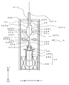
また、扉P5が閉じて機械P3が動作可能な状態のときに(図1)、何らかの原因で操作ヘッドaがスイッチ本体bから外れると(図4)、操作ロッドb2は付勢手段b4の付勢力によってさらに方向Y1へ移動し、操作ロッドb2の側面に突設されたストッパb26が筐体b1の内壁に当たり、位置決めされる。この操作ロッドb2の移動により、スイッチb3bの進退部b3eは操作ロッドb2の基準表面b22から傾斜部b25aに沿って押されて後退し、進退部b3eが頂部b25bに達したとき、スイッチb3bはオフになる。スイッチb3a、スイッチb3c、スイッチb3dについてはそれぞれオフ、オフ、オンの状態のままである(図3)。スイッチb3a、スイッチb3bが共にオフであることは操作ヘッドaがスイッチ本体bから外れていることを示す。 When the door P5 is closed and the machine P3 is operable (FIG. 1), if the operating head a is detached from the switch body b for some reason (FIG. 4), the operating rod b2 is attached to the biasing means b4. The stopper b26, which is further moved in the direction Y1 by the force and protrudes on the side surface of the operation rod b2, hits the inner wall of the housing b1, and is positioned. By this movement of the operating rod b2, the advance / retreat portion b3e of the switch b3b is pushed back from the reference surface b22 of the operation rod b2 along the inclined portion b25a, and when the advance / retreat portion b3e reaches the top portion b25b, the switch b3b is turned off. become. The switches b3a, b3c, and b3d remain off, off, and on (FIG. 3). The fact that both the switch b3a and the switch b3b are off indicates that the operation head a is detached from the switch body b.
コントローラP6はスイッチb3aのオフ、スイッチb3bのオフ、スイッチb3cのオフ、スイッチb3dのオンを受け、機械P3の動作を許可しない。 The controller P6 receives the OFF of the switch b3a, the OFF of the switch b3b, the OFF of the switch b3c, and the ON of the switch b3d, and does not permit the operation of the machine P3.
以上のように、本実施の形態の安全スイッチは、方向Y1、方向Y2に移動可能で、側面に複数の段差(傾斜部b23a、傾斜部b23c、傾斜部b24a、傾斜部b24c、傾斜部b25aにおける頂部と基準表面b22との差)のある操作ロッドb2と、外部からアクチュエータcが抜差しされ、アクチュエータcの抜差しに応じて操作ロッドb2を移動させる操作ヘッドaと、操作ロッドb2の側面に沿って進退することでオンあるいはオフする複数のスイッチb3a、スイッチb3b、スイッチb3c、スイッチb3bとを備えたことにより、操作ロッドb2の様々な位置を検出することが可能である。例えば、スイッチb3a、スイッチb3bのオンあるいはオフについて、図1ではそれぞれオフ、オン、操作ロッドb2が上方へ移動した図3の状態ではそれぞれオン、オフ、操作ロッドb2がさらに上方へ移動した図4ではそれぞれオフ、オフになり、専用のスイッチを設けるなくても、操作ヘッドaが外れたことを検出できる。このように、操作ロッドb2の様々な位置、すなわち、動作状態を検出することができ、細かな制御が可能になる。しかも、専用のスイッチを設ける必要がないので、構成が簡単、小型になる。 As described above, the safety switch of the present embodiment is movable in the direction Y1 and the direction Y2, and has a plurality of steps on the side surface (in the inclined part b23a, the inclined part b23c, the inclined part b24a, the inclined part b24c, and the inclined part b25a). The operation rod b2 having a difference between the top and the reference surface b22), the actuator c is inserted and removed from the outside, and the operation rod b2 is moved in accordance with the insertion and removal of the actuator c, and along the side surface of the operation rod b2 By providing a plurality of switches b3a, switches b3b, switches b3c, and switches b3b that are turned on or off by advancing and retreating, it is possible to detect various positions of the operating rod b2. For example, regarding the on / off of the switch b3a and the switch b3b, FIG. 4 shows that the on / off state and the operation rod b2 are further moved upward in the state of FIG. Then, it is turned off and off, respectively, and it is possible to detect that the operation head a is detached without providing a dedicated switch. In this way, various positions of the operating rod b2, that is, operating states can be detected, and fine control is possible. In addition, since there is no need to provide a dedicated switch, the configuration is simple and small.
また、偏心カムa2は操作ロッドb2を図2から図3に示す範囲しか移動させることができないが、ロック部b5はその範囲外の図1や図4に示す位置へ操作ロッドb2を移動させることが可能であり、操作ロッドb2の側面の段差のうち、傾斜部b23cや傾斜部b25aにおける段差は操作ロッドb2が図1や図4に示す前述の範囲外に移動しているとき、スイッチb3bをオン、オフさせる。これによって、ロック部b5の作用による操作ロッドb2の移動を検出することができる。特に、図1に示すように操作ロッドb2の先端が偏心カムa2の凹部a24(所定領域)内に移動したとき、傾斜部b23cにおける段差によってスイッチb3bがオンすることで操作ヘッドaがロックされたことを検出することができ、図1の操作ヘッドaが筐体b1から外れて、操作ロッドb2の先端が筐体b1からさらに離れて図4に示す領域に移動したとき、傾斜部b25aにおける段差によってスイッチb3bがオフすることで操作ヘッドaが筐体b1から外れたことを検出することができる。 The eccentric cam a2 can move the operating rod b2 only within the range shown in FIGS. 2 to 3, but the lock b5 moves the operating rod b2 to the position shown in FIGS. 1 and 4 outside the range. Among the steps on the side surface of the operating rod b2, the steps on the inclined portion b23c and the inclined portion b25a can be switched when the operating rod b2 is moved out of the aforementioned range shown in FIGS. Turn on and off. Thereby, the movement of the operation rod b2 due to the action of the lock part b5 can be detected. In particular, as shown in FIG. 1, when the tip of the operation rod b2 moves into the recess a24 (predetermined region) of the eccentric cam a2, the operation head a is locked by turning on the switch b3b by the step in the inclined portion b23c. When the operation head a in FIG. 1 is detached from the housing b1 and the tip of the operation rod b2 is further away from the housing b1 and moves to the region shown in FIG. 4, a step in the inclined portion b25a is detected. By turning off the switch b3b, it is possible to detect that the operation head a is detached from the housing b1.
また、ロックされていないこと、ロックされていること、扉が開いていること、扉が閉じていることはそれぞれスイッチb3a、スイッチb3b、スイッチb3c、スイッチb3dがオンすることで示されるが、以上のような構成により、これら全てのスイッチをb接点(押すと接点間が開く)で構成することができる。これにより、全てのスイッチについて、内蔵の接点同士が溶着しても、スイッチの進退部b3eを押すことで溶着した接点同士を強制的に引き離すことができ、安全性が増す。 In addition, the fact that it is not locked, locked, that the door is open, and that the door is closed is indicated by turning on the switch b3a, the switch b3b, the switch b3c, and the switch b3d. With such a configuration, all these switches can be configured with b contacts (when pressed, the contacts are opened). Thereby, even if the built-in contacts are welded to each other for all the switches, the welded contacts can be forcibly separated by pressing the advance / retreat portion b3e of the switch, and safety is increased.
また、操作ロッドb2の方向Y1とスイッチの進退部b3eの進退方向X1とが交差(図では直交)しているため、より多くのスイッチを設けても、安全スイッチの方向Y1の長さが長くはならない。また、操作ロッドb2の方向Y1とスイッチの進退部b3eの進退方向X1とが交差しているため、進退部b3eが基準表面b22あるいは台形状凸部の頂部に達している状態において、スイッチに内蔵の付勢手段による付勢力が操作ロッドb2を方向Y1へ移動させることへの影響が少ないため、その分、ソレノイドb51の励磁力を低くでき、ソレノイドb51を小型化、低電力化できる。 Further, since the direction Y1 of the operating rod b2 and the advance / retreat direction X1 of the switch advance / retreat part b3e intersect (orthogonal in the figure), the length of the safety switch direction Y1 is long even if more switches are provided. Must not. Also, since the direction Y1 of the operating rod b2 and the advance / retreat direction X1 of the switch advance / retreat part b3e intersect, the switch is built in the state where the advance / retreat part b3e reaches the reference surface b22 or the top of the trapezoidal convex part. Since the urging force of the urging means has little influence on the movement of the operating rod b2 in the direction Y1, the exciting force of the solenoid b51 can be reduced accordingly, and the solenoid b51 can be reduced in size and power consumption.
また、スイッチb3a及びスイッチb3bとスイッチb3c及びスイッチb3dとは操作ロッドb2を介して対向して配置されているため、操作ロッドb2が傾くなどの異常が発生しにくい。 In addition, since the switch b3a and the switch b3b and the switch b3c and the switch b3d are arranged to face each other via the operation rod b2, an abnormality such as the operation rod b2 being inclined hardly occurs.
なお、本発明は図示するものに限らない。例えば、第1の操作部は外部からアクチュエータが抜差しされ、アクチュエータの抜差しに応じて移動体を移動させるものであればよく、実施の形態では偏心カムa2を用いて構成したが、偏心カムa2以外を用いて構成してもよい。また、第2の操作部は実施の形態ではソレノイドb51、保持部b52、付勢手段b53を含んで構成したが、それら以外を用いて構成してもよい。 In addition, this invention is not restricted to what is illustrated. For example, the first operation unit may be any unit as long as the actuator is inserted and removed from the outside and the movable body is moved in accordance with the insertion and removal of the actuator. In the embodiment, the first operation unit is configured using the eccentric cam a2, but other than the eccentric cam a2. You may comprise using. Moreover, although the 2nd operation part comprised the solenoid b51, the holding | maintenance part b52, and the urging | biasing means b53 in embodiment, you may comprise using them.
a 操作ヘッド、b1 筐体、b2 操作ロッド、b3a,b3b,b3c,b3d スイッチ、b5 ロック部、c アクチュエータ。 a operation head, b1 housing, b2 operation rod, b3a, b3b, b3c, b3d switch, b5 lock part, c actuator.
Claims (4)
外部からアクチュエータが抜差しされ、当該アクチュエータの抜差しに応じて前記移動体を移動させる第1の操作部と、
前記移動体の側面に沿って進退することでオンあるいはオフする複数のスイッチと、
を備えた安全スイッチ。 A movable body that is movable in a predetermined direction and has a plurality of steps on a side surface;
A first operation unit that is inserted and removed from outside, and that moves the moving body according to the insertion and removal of the actuator;
A plurality of switches that are turned on or off by moving back and forth along the side surface of the moving body;
Safety switch with
前記複数の段差のうち少なくとも1つは、前記移動体が前記範囲外に移動しているときに、前記スイッチをオンあるいはオフさせる請求項1に記載の安全スイッチ。 A second operation unit capable of moving the movable body outside a range in which the first operation unit can move the movable body;
2. The safety switch according to claim 1, wherein at least one of the plurality of steps is configured to turn on or off the switch when the moving body moves out of the range.
前記第2の操作部は前記移動体を前記第1の操作部の所定領域に差し込むことで、前記第1の操作部の動作を固定する請求項2に記載の安全スイッチ。 Outside the range includes a predetermined area in the first operation unit,
The safety switch according to claim 2, wherein the second operation unit fixes the operation of the first operation unit by inserting the movable body into a predetermined region of the first operation unit.
前記範囲外には、前記筐体外の所定領域を含み、
前記第1の操作部が前記筐体から外れると、前記第2の操作部は前記移動体を前記筐体外の所定領域へ移動させる請求項2に記載の安全スイッチ。 The mobile body and the plurality of switches are incorporated, and further includes a housing attached to the first operation unit,
Outside the range includes a predetermined area outside the housing,
The safety switch according to claim 2, wherein when the first operation unit is detached from the housing, the second operation unit moves the movable body to a predetermined region outside the housing.
Priority Applications (1)
| Application Number | Priority Date | Filing Date | Title |
|---|---|---|---|
| JP2004107716A JP4402501B2 (en) | 2004-03-31 | 2004-03-31 | Safety switch |
Applications Claiming Priority (1)
| Application Number | Priority Date | Filing Date | Title |
|---|---|---|---|
| JP2004107716A JP4402501B2 (en) | 2004-03-31 | 2004-03-31 | Safety switch |
Publications (2)
| Publication Number | Publication Date |
|---|---|
| JP2005294047A true JP2005294047A (en) | 2005-10-20 |
| JP4402501B2 JP4402501B2 (en) | 2010-01-20 |
Family
ID=35326746
Family Applications (1)
| Application Number | Title | Priority Date | Filing Date |
|---|---|---|---|
| JP2004107716A Expired - Lifetime JP4402501B2 (en) | 2004-03-31 | 2004-03-31 | Safety switch |
Country Status (1)
| Country | Link |
|---|---|
| JP (1) | JP4402501B2 (en) |
Cited By (7)
| Publication number | Priority date | Publication date | Assignee | Title |
|---|---|---|---|---|
| WO2007066803A1 (en) * | 2005-12-09 | 2007-06-14 | Idec Corporation | Safety switch |
| JP2009544125A (en) * | 2006-07-19 | 2009-12-10 | オイフナー ゲゼルシャフト ミット ベシュレンクテル ハフツング ウント コンパニー コマンディト ゲゼルシャフト | Equipment for monitoring the state of protective devices on machines |
| JP2010123306A (en) * | 2008-11-18 | 2010-06-03 | Idec Corp | Safety switch |
| JP2010123305A (en) * | 2008-11-18 | 2010-06-03 | Idec Corp | Safety system |
| WO2020175413A1 (en) * | 2019-02-27 | 2020-09-03 | Idec株式会社 | Operation switch unit with operation assistance function, operation unit with operation assistance function, and operation assistance system |
| JP2020188079A (en) * | 2019-05-10 | 2020-11-19 | Idec株式会社 | Solenoid drive controller and safety switch having the same |
| DE102022100787A1 (en) | 2021-01-22 | 2022-07-28 | Idec Corporation | SAFETY SWITCH |
-
2004
- 2004-03-31 JP JP2004107716A patent/JP4402501B2/en not_active Expired - Lifetime
Cited By (13)
| Publication number | Priority date | Publication date | Assignee | Title |
|---|---|---|---|---|
| WO2007066803A1 (en) * | 2005-12-09 | 2007-06-14 | Idec Corporation | Safety switch |
| JP2009544125A (en) * | 2006-07-19 | 2009-12-10 | オイフナー ゲゼルシャフト ミット ベシュレンクテル ハフツング ウント コンパニー コマンディト ゲゼルシャフト | Equipment for monitoring the state of protective devices on machines |
| JP2010123306A (en) * | 2008-11-18 | 2010-06-03 | Idec Corp | Safety switch |
| JP2010123305A (en) * | 2008-11-18 | 2010-06-03 | Idec Corp | Safety system |
| JP7286344B2 (en) | 2019-02-27 | 2023-06-05 | Idec株式会社 | Operation switch unit with operation support function, operation unit with operation support function and operation support system |
| WO2020175413A1 (en) * | 2019-02-27 | 2020-09-03 | Idec株式会社 | Operation switch unit with operation assistance function, operation unit with operation assistance function, and operation assistance system |
| JP2020140828A (en) * | 2019-02-27 | 2020-09-03 | Idec株式会社 | Operation switch unit with operation support function, operation unit with operation support function, and operation support system |
| US11942288B2 (en) | 2019-02-27 | 2024-03-26 | Idec Corporation | Operation switch unit with operation support function, operation unit with operation support function, and operation support system |
| JP2020188079A (en) * | 2019-05-10 | 2020-11-19 | Idec株式会社 | Solenoid drive controller and safety switch having the same |
| CN113785376A (en) * | 2019-05-10 | 2021-12-10 | Idec株式会社 | Drive control device for solenoid and safety switch provided with same |
| JP7345272B2 (en) | 2019-05-10 | 2023-09-15 | Idec株式会社 | Solenoid drive control device and safety switch equipped with the same |
| WO2020230547A1 (en) * | 2019-05-10 | 2020-11-19 | Idec株式会社 | Drive control device for solenoid, and safety switch provided therewith |
| DE102022100787A1 (en) | 2021-01-22 | 2022-07-28 | Idec Corporation | SAFETY SWITCH |
Also Published As
| Publication number | Publication date |
|---|---|
| JP4402501B2 (en) | 2010-01-20 |
Similar Documents
| Publication | Publication Date | Title |
|---|---|---|
| JP4620598B2 (en) | Emergency stop pushbutton switch | |
| JP4402501B2 (en) | Safety switch | |
| JP4486049B2 (en) | Machine with safety door | |
| WO2019006309A1 (en) | Locking device with anti-jam mechanism | |
| JP4727290B2 (en) | Safety switch | |
| US7605335B2 (en) | Position switch | |
| US20200219678A1 (en) | Switching apparatus and associated switch | |
| US6483053B2 (en) | Lock switch apparatus | |
| JP4396478B2 (en) | Key switch | |
| JP4763696B2 (en) | Device for monitoring the state of the protection mechanism | |
| KR101524539B1 (en) | Key switch | |
| JP4493073B2 (en) | Safety switch | |
| WO2006117965A1 (en) | Safety switch | |
| JP3938275B2 (en) | Safety switch | |
| JP6737876B2 (en) | Safety switch | |
| JP6746248B2 (en) | Injection molding machine safety door | |
| JP2004356069A (en) | Safety switch | |
| US4778954A (en) | Switching device to be operated by means of a cylinder lock | |
| JP4805805B2 (en) | Switch device | |
| JP4119192B2 (en) | Push button switch | |
| JP2004107902A (en) | Locking/unlocking device for cabinet | |
| JP7542427B2 (en) | Operation switches, emergency stop switches and control systems | |
| JP4700398B2 (en) | Safety switch | |
| JP2006120480A (en) | Key switch | |
| JP2005053336A (en) | Steering lock device |
Legal Events
| Date | Code | Title | Description |
|---|---|---|---|
| A621 | Written request for application examination |
Free format text: JAPANESE INTERMEDIATE CODE: A621 Effective date: 20061110 |
|
| A131 | Notification of reasons for refusal |
Free format text: JAPANESE INTERMEDIATE CODE: A131 Effective date: 20090316 |
|
| A521 | Request for written amendment filed |
Free format text: JAPANESE INTERMEDIATE CODE: A523 Effective date: 20090515 |
|
| A131 | Notification of reasons for refusal |
Free format text: JAPANESE INTERMEDIATE CODE: A131 Effective date: 20090730 |
|
| A521 | Request for written amendment filed |
Free format text: JAPANESE INTERMEDIATE CODE: A523 Effective date: 20090928 |
|
| TRDD | Decision of grant or rejection written | ||
| A01 | Written decision to grant a patent or to grant a registration (utility model) |
Free format text: JAPANESE INTERMEDIATE CODE: A01 Effective date: 20091026 |
|
| A01 | Written decision to grant a patent or to grant a registration (utility model) |
Free format text: JAPANESE INTERMEDIATE CODE: A01 |
|
| A61 | First payment of annual fees (during grant procedure) |
Free format text: JAPANESE INTERMEDIATE CODE: A61 Effective date: 20091029 |
|
| R150 | Certificate of patent or registration of utility model |
Ref document number: 4402501 Country of ref document: JP Free format text: JAPANESE INTERMEDIATE CODE: R150 Free format text: JAPANESE INTERMEDIATE CODE: R150 |
|
| FPAY | Renewal fee payment (event date is renewal date of database) |
Free format text: PAYMENT UNTIL: 20121106 Year of fee payment: 3 |
|
| FPAY | Renewal fee payment (event date is renewal date of database) |
Free format text: PAYMENT UNTIL: 20121106 Year of fee payment: 3 |
|
| FPAY | Renewal fee payment (event date is renewal date of database) |
Free format text: PAYMENT UNTIL: 20131106 Year of fee payment: 4 |
|
| S531 | Written request for registration of change of domicile |
Free format text: JAPANESE INTERMEDIATE CODE: R313531 |
|
| R350 | Written notification of registration of transfer |
Free format text: JAPANESE INTERMEDIATE CODE: R350 |
|
| EXPY | Cancellation because of completion of term |