JP2005293945A - Plasma heating device, and electrode with nozzle - Google Patents
Plasma heating device, and electrode with nozzle Download PDFInfo
- Publication number
- JP2005293945A JP2005293945A JP2004105130A JP2004105130A JP2005293945A JP 2005293945 A JP2005293945 A JP 2005293945A JP 2004105130 A JP2004105130 A JP 2004105130A JP 2004105130 A JP2004105130 A JP 2004105130A JP 2005293945 A JP2005293945 A JP 2005293945A
- Authority
- JP
- Japan
- Prior art keywords
- electrode
- nozzle
- plasma
- plasma arc
- gas
- Prior art date
- Legal status (The legal status is an assumption and is not a legal conclusion. Google has not performed a legal analysis and makes no representation as to the accuracy of the status listed.)
- Pending
Links
- 238000010438 heat treatment Methods 0.000 title claims abstract description 140
- 238000002347 injection Methods 0.000 claims description 29
- 239000007924 injection Substances 0.000 claims description 29
- 230000007246 mechanism Effects 0.000 claims description 9
- WFKWXMTUELFFGS-UHFFFAOYSA-N tungsten Chemical compound [W] WFKWXMTUELFFGS-UHFFFAOYSA-N 0.000 claims description 9
- 229910052721 tungsten Inorganic materials 0.000 claims description 9
- 239000010937 tungsten Substances 0.000 claims description 9
- 239000007772 electrode material Substances 0.000 claims description 5
- OKTJSMMVPCPJKN-UHFFFAOYSA-N Carbon Chemical compound [C] OKTJSMMVPCPJKN-UHFFFAOYSA-N 0.000 claims description 3
- 229910052799 carbon Inorganic materials 0.000 claims description 3
- 239000000126 substance Substances 0.000 abstract description 17
- 238000007599 discharging Methods 0.000 abstract 3
- 239000007789 gas Substances 0.000 description 159
- 238000010586 diagram Methods 0.000 description 25
- 238000012545 processing Methods 0.000 description 21
- 230000008901 benefit Effects 0.000 description 18
- 230000001681 protective effect Effects 0.000 description 15
- 239000000463 material Substances 0.000 description 10
- IJGRMHOSHXDMSA-UHFFFAOYSA-N Atomic nitrogen Chemical compound N#N IJGRMHOSHXDMSA-UHFFFAOYSA-N 0.000 description 8
- 239000004020 conductor Substances 0.000 description 8
- 238000000034 method Methods 0.000 description 7
- XKRFYHLGVUSROY-UHFFFAOYSA-N Argon Chemical compound [Ar] XKRFYHLGVUSROY-UHFFFAOYSA-N 0.000 description 6
- 230000008859 change Effects 0.000 description 6
- 230000000694 effects Effects 0.000 description 6
- 238000012546 transfer Methods 0.000 description 6
- 230000007704 transition Effects 0.000 description 6
- 239000002440 industrial waste Substances 0.000 description 5
- 239000012811 non-conductive material Substances 0.000 description 5
- 229910052786 argon Inorganic materials 0.000 description 4
- 238000001816 cooling Methods 0.000 description 4
- 229910052734 helium Inorganic materials 0.000 description 4
- 239000011261 inert gas Substances 0.000 description 4
- 229910052757 nitrogen Inorganic materials 0.000 description 4
- XLYOFNOQVPJJNP-UHFFFAOYSA-N water Substances O XLYOFNOQVPJJNP-UHFFFAOYSA-N 0.000 description 4
- 238000010891 electric arc Methods 0.000 description 3
- 239000001307 helium Substances 0.000 description 3
- SWQJXJOGLNCZEY-UHFFFAOYSA-N helium atom Chemical compound [He] SWQJXJOGLNCZEY-UHFFFAOYSA-N 0.000 description 3
- 229910052751 metal Inorganic materials 0.000 description 3
- 239000002184 metal Substances 0.000 description 3
- 230000005012 migration Effects 0.000 description 3
- 238000013508 migration Methods 0.000 description 3
- 239000000203 mixture Substances 0.000 description 3
- 230000005855 radiation Effects 0.000 description 3
- RYGMFSIKBFXOCR-UHFFFAOYSA-N Copper Chemical compound [Cu] RYGMFSIKBFXOCR-UHFFFAOYSA-N 0.000 description 2
- 229910001080 W alloy Inorganic materials 0.000 description 2
- 238000009835 boiling Methods 0.000 description 2
- 238000006243 chemical reaction Methods 0.000 description 2
- 230000000052 comparative effect Effects 0.000 description 2
- 229910052802 copper Inorganic materials 0.000 description 2
- 239000010949 copper Substances 0.000 description 2
- 238000001784 detoxification Methods 0.000 description 2
- 150000002013 dioxins Chemical class 0.000 description 2
- 238000010494 dissociation reaction Methods 0.000 description 2
- 230000005593 dissociations Effects 0.000 description 2
- 239000002906 medical waste Substances 0.000 description 2
- -1 needles Substances 0.000 description 2
- 229910052760 oxygen Inorganic materials 0.000 description 2
- 230000008569 process Effects 0.000 description 2
- 239000002893 slag Substances 0.000 description 2
- 230000001954 sterilising effect Effects 0.000 description 2
- 229910001029 Hf alloy Inorganic materials 0.000 description 1
- 241000700605 Viruses Species 0.000 description 1
- QVGXLLKOCUKJST-UHFFFAOYSA-N atomic oxygen Chemical compound [O] QVGXLLKOCUKJST-UHFFFAOYSA-N 0.000 description 1
- 239000008280 blood Substances 0.000 description 1
- 210000004369 blood Anatomy 0.000 description 1
- 239000000919 ceramic Substances 0.000 description 1
- 238000002485 combustion reaction Methods 0.000 description 1
- 239000012141 concentrate Substances 0.000 description 1
- 238000011038 discontinuous diafiltration by volume reduction Methods 0.000 description 1
- 239000012530 fluid Substances 0.000 description 1
- 229910052735 hafnium Inorganic materials 0.000 description 1
- VBJZVLUMGGDVMO-UHFFFAOYSA-N hafnium atom Chemical compound [Hf] VBJZVLUMGGDVMO-UHFFFAOYSA-N 0.000 description 1
- 229910001385 heavy metal Inorganic materials 0.000 description 1
- 238000005304 joining Methods 0.000 description 1
- 230000007774 longterm Effects 0.000 description 1
- 238000004519 manufacturing process Methods 0.000 description 1
- 238000002844 melting Methods 0.000 description 1
- 230000008018 melting Effects 0.000 description 1
- 238000012986 modification Methods 0.000 description 1
- 230000004048 modification Effects 0.000 description 1
- NJPPVKZQTLUDBO-UHFFFAOYSA-N novaluron Chemical compound C1=C(Cl)C(OC(F)(F)C(OC(F)(F)F)F)=CC=C1NC(=O)NC(=O)C1=C(F)C=CC=C1F NJPPVKZQTLUDBO-UHFFFAOYSA-N 0.000 description 1
- 239000011368 organic material Substances 0.000 description 1
- 239000001301 oxygen Substances 0.000 description 1
- 229920003023 plastic Polymers 0.000 description 1
- 239000004033 plastic Substances 0.000 description 1
- 230000001737 promoting effect Effects 0.000 description 1
- 239000002689 soil Substances 0.000 description 1
- 239000007787 solid Substances 0.000 description 1
- 239000002910 solid waste Substances 0.000 description 1
- 238000007711 solidification Methods 0.000 description 1
- 230000008023 solidification Effects 0.000 description 1
- 239000007921 spray Substances 0.000 description 1
- 230000006641 stabilisation Effects 0.000 description 1
- 238000011105 stabilization Methods 0.000 description 1
- 239000007858 starting material Substances 0.000 description 1
- 238000004659 sterilization and disinfection Methods 0.000 description 1
- 230000001052 transient effect Effects 0.000 description 1
- 238000004056 waste incineration Methods 0.000 description 1
- 239000002699 waste material Substances 0.000 description 1
Images


Landscapes
- Discharge Heating (AREA)
- Physical Or Chemical Processes And Apparatus (AREA)
- Crucibles And Fluidized-Bed Furnaces (AREA)
- Furnace Details (AREA)
- Plasma Technology (AREA)
Abstract
Description
本発明は、単数または複数のノズル付き電極から電子を含む高温ガス流であるプラズマアークを出力し、当該プラズマアークを被加熱物に接触させて加熱するプラズマ加熱装置、および、そのプラズマ加熱装置に好適に用いることが可能なノズル付き電極に関するものである。 The present invention relates to a plasma heating apparatus that outputs a plasma arc, which is a high-temperature gas flow containing electrons, from one or more nozzle electrodes, and heats the plasma arc by contacting an object to be heated, and the plasma heating apparatus. The present invention relates to an electrode with a nozzle that can be suitably used.
プラズマ加熱を行うためのノズル付き電極としては、ノズル付き電極内部の電極間に電圧を印加して超高温度アークを発生させ被加熱物に対しては電子を殆ど含まない高温ガス流を噴射する非移行型のプラズマジェットと、ノズル付き電極内部の電極と被加熱物との間に電圧を印加して超高温度アークを発生させ、この超高温度アークを被加熱物の表面にまで移行させ(この移行後の超高温度アークを、以下、トーチプラズマアーク、または、単にプラズマアークという)により直接、被加熱物を加熱する移行型のノズル付き電極(プラズマトーチ)とに大別される。
移行型は被加熱物に電圧を印加する必要があることから導電性物質や高沸点物質の加熱に適しているが、電流が通しにくい非導電性物質の処理が苦手である。これに対し、非移行型は被加熱物が導電性であることを必要としないため非導電性物質の加熱も可能であるが、温度が低いことから高融点物質や無機物の処理が苦手である。
As an electrode with a nozzle for performing plasma heating, a voltage is applied between electrodes inside the electrode with a nozzle to generate an ultra-high temperature arc, and a high-temperature gas flow containing almost no electrons is injected to the object to be heated. A voltage is applied between the non-migration type plasma jet and the electrode inside the electrode with nozzle and the object to be heated to generate an ultra high temperature arc, and this ultra high temperature arc is transferred to the surface of the object to be heated. (The ultra-high temperature arc after the transition will be roughly divided into a transition type nozzle-equipped electrode (plasma torch) that directly heats an object to be heated by a torch plasma arc or simply a plasma arc).
The transfer type is suitable for heating a conductive substance or a high boiling point substance because a voltage needs to be applied to an object to be heated, but is not good at processing a non-conductive substance that is difficult to pass current. On the other hand, the non-migrating type does not require the object to be heated to be conductive, so it can also heat non-conductive substances, but because of its low temperature, it is not good at treating high melting point substances and inorganic substances. .
このようなプラズマ加熱のうち、とくにプラズマトーチから出力される移行型のトーチプラズマアークは、超高温熱源あるいは超高輝度放射源としての種々の用途がある。そして、一般には、複数のノズル付き電極を用いる場合が多い。たとえば導電性を有する溶融金属を加熱するために複数のノズル付き電極を用いる技術が知られている(特許文献1参照)。
この特許文献1に記載の技術では、それぞれ棒状の金属電極を備える複数のノズル付き電極が、加熱対象物の離れた位置で、各先端部が所定間隔を隔てて加熱対象物に近接するように垂直状態に配置される。したがって電流が加熱対象物に流れ、そのジュール熱も加熱に寄与することから加熱効率は高い。ところが、加熱対象物が導電性の固体または流体に限定され、その点で用途が限定される。
Among such plasma heating, a transition type torch plasma arc output from a plasma torch in particular has various uses as an ultra-high temperature heat source or an ultra-high brightness radiation source. In general, a plurality of nozzle electrodes are often used. For example, a technique using a plurality of nozzle-equipped electrodes to heat molten metal having conductivity is known (see Patent Document 1).
In the technique described in
これに対し、近年は超高温熱源として廃棄物処理などへの用途が注目され、そのために適した構成のプラズマ加熱装置が知られている(たとえば、特許文献2あるいは非特許文献1参照)。
産業廃棄物は無機物や有機物など導電性が異なる物質が混在することから、被加熱物の導電性に依存しないプラズマ加熱時の電流経路を確保する必要がある。そのため、複数のノズル付き電極を用い、かつ、正電極側のプラズマアークと負電極側のプラズマアークとを接触させ、プラズマアークを介する電流経路の形成が必要である。
特許文献2では、3本の電極棒(ノズル付き電極)を逆円錐状に配置し、各電極にはパルス波状の3相交流を通電しているが、ノズル付き電極の配置の詳細は示されていない。また、非特許文献1では、V字型プラズマアークが形成されるように2本のノズル付き電極を先端ほど互いの距離が近くなるように配置し、その一方に陽極側電圧を、他方に陰極側電圧を印加している。
On the other hand, in recent years, attention has been focused on the use of waste treatment as an ultra-high temperature heat source, and a plasma heating apparatus having a configuration suitable for this purpose is known (for example, see
Since industrial waste contains a mixture of inorganic and organic substances having different electrical conductivity, it is necessary to secure a current path during plasma heating that does not depend on the electrical conductivity of the object to be heated. For this reason, it is necessary to form a current path through the plasma arc by using a plurality of electrodes with nozzles and bringing the plasma arc on the positive electrode side into contact with the plasma arc on the negative electrode side.
In
このように複数のノズル付き電極を用いると、移行型でありながらプラズマ加熱時の電流経路を確保できる。そのため、被加熱物の導電性に依存しない高温度アークの生成が可能で、産業廃棄物などの様々な材質が混在している場合の加熱処理に適したプラズマ加熱装置を実現できる。このときのプラズマ加熱は移行型であることから極めて高い温度の処理が可能であり、埋め立てると周辺土壌に深刻な影響を与える重金属などの物質をスラグにすることにより閉じ込めて無害化できる。さらに、炉で焼却すると不完全燃焼によるダイオキシンなどの有害物質が発生しやすいが、プラズマ加熱ではダイオキシンなどの有害物質の無害化することが可能である。
特許文献2に記載のプラズマ加熱装置では、交流電源により発生したプラズマアーク(以下、交流アークという)を用いている。しかし、交流アークでは、アークの発生、および、安定したアークの持続が困難である。このため、スタータとしての直流電源を別途設ける必要があり、装置規模やコストが増大するという欠点がある。
一方、非特許文献1に記載のプラズマ加熱装置では、直流電源により発生したプラズマアーク(以下、直流アークという)を用いることから、アークの発生および安定したアークの持続が容易である。
In the plasma heating apparatus described in
On the other hand, in the plasma heating apparatus described in Non-Patent
ところが従来のプラズマ加熱装置では、交流アーク、直流アークに限らず、プラズマアークを接触させて電流経路を確保する必要から、その接触点付近での加熱が基本となる。したがって、狭い領域にエネルギーが集中しやすいことから、処理面積が狭くなるという課題がある。つまり、このような複数のプラズマアークを1点に集中させて用いる場合は、ある程度大きな電流で高い温度まで加熱しやすいが、太いアークを得ようとして電流を上げると若干はアーク径を太くできるが、電流量を上げることだけでは処理のための高温領域の拡大に限度がある。また、大きな電流を流すための電源設備は高価でありコストが高くなる。このように、従来のプラズマ加熱装置は、設備コストを抑制しながら加熱面積を大きくすることが不可能である。
また、とくに従来のノズル付き電極は、電極の保護のために電極の先端以外をノズル枠体で覆った構造が採用されることが多く、その場合にアーク自体が細くなりがちである。さらに、いわゆるV字アークではプラズマアークの接触点付近での加熱を前提とすることから、加熱処理可能な深さ方向の距離も小さい。
However, the conventional plasma heating apparatus is not limited to an AC arc and a DC arc, and since it is necessary to secure a current path by contacting the plasma arc, heating near the contact point is fundamental. Therefore, there is a problem that the processing area becomes narrow because energy tends to concentrate in a narrow region. That is, when such a plurality of plasma arcs are concentrated on one point, it is easy to heat to a high temperature with a certain amount of current, but if the current is increased to obtain a thick arc, the arc diameter can be slightly increased. Only by increasing the amount of current, there is a limit to the expansion of the high temperature region for processing. Moreover, the power supply equipment for flowing a large current is expensive and expensive. Thus, the conventional plasma heating apparatus cannot increase the heating area while suppressing the equipment cost.
In particular, a conventional electrode with a nozzle often employs a structure in which a portion other than the tip of the electrode is covered with a nozzle frame for protection of the electrode, and in this case, the arc itself tends to be thin. Furthermore, since the so-called V-shaped arc presupposes heating near the contact point of the plasma arc, the distance in the depth direction that can be heat-treated is also small.
本発明が解決しようとする課題は、直流電源により発生させた複数のプラズマアークを接触させて用いるタイプのプラズマ加熱装置において、その加熱処理可能な面積や深さを容易に大きくし、また、そのために適した構造のノズル付き電極を提供することにある。 The problem to be solved by the present invention is to easily increase the area and depth of heat treatment in a plasma heating apparatus of a type that uses a plurality of plasma arcs generated by a direct current power supply in contact with each other. It is an object to provide an electrode with a nozzle having a structure suitable for the above.
本発明に係るプラズマ加熱装置は、単数または複数のノズル付き電極から電子を含む高温ガス流であるプラズマアークを出力し、当該プラズマアークを被加熱物に接触させて加熱するプラズマ加熱装置であって、複数のノズル付き電極の電極間またはノズル付き電極の電極と被加熱物との間に直流電圧を供給し、複数のノズル付き電極から直流電流の経路となるプラズマアークを出力させる直流電源と、前記プラズマアークにガスまたは高温ガス流を噴射し、当該プラズマアークの被加熱物への接触状態を制御する加熱部制御手段とを備える。 A plasma heating apparatus according to the present invention is a plasma heating apparatus that outputs a plasma arc, which is a high-temperature gas flow containing electrons, from one or more electrodes with nozzles, and heats the plasma arc in contact with an object to be heated. A DC power source that supplies a DC voltage between the electrodes of the plurality of nozzle-equipped electrodes or between the electrode of the nozzle-equipped electrode and the object to be heated, and outputs a plasma arc serving as a path of a DC current from the plurality of nozzle-equipped electrodes; A heating unit control means is provided for injecting a gas or a high-temperature gas flow into the plasma arc and controlling a contact state of the plasma arc with an object to be heated.
前記加熱部制御手段は、前記プラズマアークに高温ガス流を出力可能な加熱部制御用のノズル付き電極を含み、当該加熱部制御用のノズル付き電極からガスおよび/または高温ガス流を噴射することによってプラズマアークの被加熱物への接触状態を制御する構成が望ましい。 The heating unit control means includes an electrode with a nozzle for heating unit control capable of outputting a high-temperature gas flow to the plasma arc, and jets a gas and / or a high-temperature gas flow from the electrode with a nozzle for heating unit control It is desirable to control the contact state of the plasma arc with the object to be heated.
また、前記加熱部制御手段は、ガスを噴射可能なノズル付き電極またはノズルからなるガス噴射部と、当該ガス噴射部から加熱部制御用に噴射するガスの単位時間当たりの流量を制御する第1のガス流量制御部と、前記ノズル付き電極が、プラズマアークを出力する電極と当該電極の周囲にガスの通路となる隙間を形成するノズル枠体とを備えている場合に、当該ノズル付き電極から出力されるガスの単位時間当たりの流量を制御する第2のガス流量制御部と、を含む構成が望ましい。 The heating unit control means controls a gas injection unit including a nozzle-equipped electrode or nozzle capable of injecting gas, and a flow rate per unit time of gas injected from the gas injection unit for heating unit control. When the gas flow rate control unit and the electrode with nozzle are provided with an electrode that outputs a plasma arc and a nozzle frame that forms a gap serving as a gas passage around the electrode, the electrode with nozzle It is desirable to include a second gas flow rate control unit that controls the flow rate of the output gas per unit time.
このプラズマ加熱装置によれば、たとえば、複数のノズル付き電極のアーク出力端を互いに近接させた状態で、直流電源により、その少なくとも一つに陽極側電圧を印加し、その少なくとも一つに陰極側電圧を印加する。あるいは、ノズル付き電極と非加熱物の一方に陽極側電圧を印加し、他方に陰極側電圧を印加する。これによりプラズマアークが発生する。このプラズマアークに接触するように被加熱物の処理したい部分を近づけるのが今までの加熱方法であるが、本発明では、加熱部制御手段からガスまたは高温ガス流をプラズマアークに噴射する。本発明で「ガス」とは通常の非活性または活性のガスのことであり、「高温ガス流」とは、電子を含む超高温ガス流であるプラズマアーク、または、殆ど電子を含まない高温ガス流のことである。このときガスや高温ガス流の噴射範囲、流速あるいは噴射方向などに応じてプラズマアークの被加熱物への接触面積が大きくなる。また、噴射するガスなどの流速をある程度大きくすると、たとえば段差による深さのある形状の被加熱物の段差の表面部だけでなく底部も加熱される。 According to this plasma heating apparatus, for example, an anode side voltage is applied to at least one of the plurality of nozzle-equipped electrodes by a DC power source in a state where the arc output ends are close to each other, and at least one of the electrodes is connected to the cathode side Apply voltage. Alternatively, an anode side voltage is applied to one of the nozzle electrode and the non-heated material, and a cathode side voltage is applied to the other. As a result, a plasma arc is generated. The conventional heating method is to bring the part to be heated of the object to be processed close to the plasma arc. In the present invention, a gas or a high-temperature gas flow is jetted from the heating unit control means to the plasma arc. In the present invention, “gas” refers to a normal inactive or active gas, and “hot gas flow” refers to a plasma arc, which is an ultra-high temperature gas flow containing electrons, or a high temperature gas containing almost no electrons. It is a flow. At this time, the contact area of the plasma arc to the object to be heated increases according to the injection range, flow velocity, or injection direction of the gas or high-temperature gas flow. Further, when the flow velocity of the gas to be injected is increased to some extent, for example, not only the surface portion of the step of the heated object having a depth due to the step but also the bottom is heated.
本発明に係るノズル付き電極は、プラズマアークを出力し、当該プラズマアークを被加熱物に接触させて加熱するノズル付き電極であって、プラズマアークを出力する電極と、当該電極の周囲にガスの通路となる隙間を形成するノズル枠体と、電極の先端がノズル枠体の端面より内側の位置から外側の位置まで軸方向にスライド可能な電極のスライド機構とを備える。 An electrode with a nozzle according to the present invention is an electrode with a nozzle that outputs a plasma arc and heats the plasma arc in contact with an object to be heated, the electrode having a plasma arc, and a gas around the electrode. A nozzle frame that forms a gap serving as a passage, and an electrode sliding mechanism that can slide the tip of the electrode in the axial direction from a position inside the end surface of the nozzle frame to an outside position.
このノズル付き電極は、電極の先端がノズル枠体の端面より内側の位置から外側の位置まで軸方向にスライド可能な電極のスライド機構を備えることから、ガスの噴射口が広く、そこから多量のガスが一度に安定して噴射される。 This nozzle-equipped electrode is equipped with an electrode slide mechanism in which the tip of the electrode can slide in the axial direction from an inner position to an outer position from the end face of the nozzle frame. Gas is stably injected at a time.
本発明に係るプラズマ加熱装置によれば、加熱部制御手段を有していることから、そのガスの噴射範囲や流速などに応じてプラズマアークの被加熱物への接触面積を制御できる。また、被加熱物の表面から深い位置まで加熱が可能となる、さらには被加熱物が導電性物質からなる場合、ガスの噴射によってプラズマアークを分断して異なる箇所で被加熱物に接触させ、その結果、ジュール加熱効果が加わった効率が高いプラズマ加熱も可能となる。
このように、本装置によれば、被加熱物が導電性物質か非導電性物質かを問わず、その大きさや形状に応じて柔軟にプラズマアークの接触部を制御できるという効果が得られる。
According to the plasma heating apparatus of the present invention, since the heating unit control means is provided, the contact area of the plasma arc with the object to be heated can be controlled according to the gas injection range, the flow velocity, and the like. In addition, it is possible to heat from the surface of the object to be heated to a deep position, and when the object to be heated is made of a conductive material, the plasma arc is divided by gas injection to contact the object to be heated at different locations, As a result, high-efficiency plasma heating with the Joule heating effect added is also possible.
As described above, according to this apparatus, regardless of whether the object to be heated is a conductive substance or a non-conductive substance, it is possible to flexibly control the contact portion of the plasma arc according to the size and shape thereof.
また、本発明に係るノズル付き電極によれば、多量のガスを一度に安定して噴射できる形状であることから、加熱部制御用に用いるガスまたは高温ガス流の噴射部を、このノズル付き電極により実現できるという利点がある。このときプラズマアークと称される電子を含む超高温ガス流、あるいは、電子を殆ど含まない高温ガス流の出力が可能であり、この点でもプラズマの径の拡大に寄与できる。
また、ノズル枠体の径より小さい径の電極がノズル枠体の端面の内側の位置から外側の位置までスライド可能であることから、電極の先端同士を極限まで近づけ、電極同士を接触させ、あるいは、各電極が被加熱物に接触した状態でプラズマの発生を開始させることができるという利点がある。このため、プラズマアーク生成の開始が容易であるという効果が得られる。
Further, according to the electrode with nozzle according to the present invention, since it has a shape capable of stably injecting a large amount of gas at a time, the injection part for the gas or high-temperature gas flow used for heating part control is used as the electrode with nozzle. There is an advantage that can be realized. At this time, it is possible to output an ultra-high temperature gas flow containing electrons called a plasma arc, or a high-temperature gas flow containing almost no electrons, and this point can also contribute to the expansion of the plasma diameter.
In addition, since an electrode having a diameter smaller than the diameter of the nozzle frame can be slid from the inner position to the outer position of the end face of the nozzle frame, the tips of the electrodes are brought close to each other as much as possible, or the electrodes are brought into contact with each other, or There is an advantage that generation of plasma can be started in a state where each electrode is in contact with an object to be heated. For this reason, the effect that the start of plasma arc generation is easy is obtained.
本発明のプラズマ加熱装置は、複数のノズル付き電極の電極間またはノズル付き電極の電極と被加熱物との間に直流電圧を供給し、ノズル付き電極から直流電流の経路となるプラズマアークを出力させる直流電源と、当該プラズマアークにガスまたは高温ガス流を噴射し、当該プラズマアークの被加熱物への接触状態を制御する加熱部制御手段とを備えることを特徴とする。この加熱部制御手段は、好適に、ガス噴射部と、ガス流量制御部とを備える。 The plasma heating apparatus of the present invention supplies a DC voltage between electrodes of a plurality of nozzle electrodes or between an electrode of a nozzle electrode and an object to be heated, and outputs a plasma arc serving as a DC current path from the nozzle electrode. And a heating unit control means for controlling a contact state of the plasma arc with an object to be heated by injecting a gas or a high-temperature gas flow into the plasma arc. The heating unit control means preferably includes a gas injection unit and a gas flow rate control unit.
以下、被加熱部にも電圧を印加する場合にノズル付き電極は少なくとも1本で足りるが、ここでは、ノズル付き電極を2本組で用いるツイントーチプラズマアークを出力する2つのノズル付き電極をベースとして、その2つのノズル付き電極から出力されるツイントーチプラズマアークにガスを噴射する加熱部制御用のノズル付き電極を付加した3プラズマトーチ構成を主な例として、本発明の実施の形態を説明する。なお、加熱部制御用のノズル付き電極は、プラズマアークを出力する移行型のプラズマトーチ、プラズマアークと異なり電子を殆ど含まない高温ガス流を出力する非移行型のプラズマジェットの何れでもよい。この加熱部制御用のノズル付き電極に代えて、プラズマトーチとしての機能を備えていない通常のノズルを設けることもできる。本発明の“ガス噴射部”は、このノズルおよび加熱部制御用のノズル付き電極の総称である。また、後述するように3プラズマトーチ構成を複数設けることがきる。本実施の形態では、3プラズマトーチ構成を2つ設ける場合までを説明するが、3より多い数のノズル付き電極を有するマルチプラズマトーチ構成でもよい。 Hereinafter, when a voltage is also applied to the heated part, at least one electrode with a nozzle is sufficient, but here, based on two electrodes with a nozzle that outputs a twin torch plasma arc using two electrodes with a nozzle. As an example, a description will be given of an embodiment of the present invention, mainly using a three-plasma torch configuration in which an electrode with a nozzle for heating part control for injecting gas to a twin torch plasma arc output from the two nozzle-provided electrodes is added. To do. Note that the nozzle-equipped electrode for controlling the heating unit may be either a transfer type plasma torch that outputs a plasma arc or a non-transfer type plasma jet that outputs a high-temperature gas flow containing almost no electrons unlike the plasma arc. Instead of the nozzle-equipped electrode for controlling the heating section, a normal nozzle that does not have a function as a plasma torch can be provided. The “gas injection part” of the present invention is a general term for the nozzle and electrode with nozzle for controlling the heating part. Also, as will be described later, a plurality of three plasma torch configurations can be provided. In the present embodiment, a case where two three plasma torch configurations are provided will be described, but a multi-plasma torch configuration having more than three nozzle electrodes may be used.
[第1の実施例]
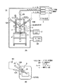
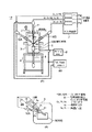
図1(A)は、第1の実施例に係るプラズマ加熱装置の構成図である。また、図1(B)は、プラズマアークの発生状態および電圧関係を示す模式図である。なお、図1(B)は、被加熱物の処理面に対して斜めの位置からプラズマアークを発生させているが、その角度は任意である。処理後のガス流を電極から遠ざけて当該ガス流の電極への影響を低減するという意味では、このような斜めからのプラズマアーク処理が望ましい。ただし、そのような電極への影響を考慮する必要がない場合は、被加熱物の処理面に対して垂直にプラズマアークを当てることも可能である。
[First embodiment]
FIG. 1A is a configuration diagram of the plasma heating apparatus according to the first embodiment. FIG. 1B is a schematic diagram showing a plasma arc generation state and a voltage relationship. In FIG. 1B, the plasma arc is generated from a position oblique to the processing surface of the object to be heated, but the angle is arbitrary. In order to reduce the influence of the gas flow on the electrode by moving the gas flow after the treatment away from the electrode, such an oblique plasma arc treatment is desirable. However, when it is not necessary to consider such an influence on the electrode, it is possible to apply a plasma arc perpendicular to the processing surface of the object to be heated.
図1(A)に示すプラズマ加熱装置1Aは、ロータリーポンプ2により内部が真空引きされるチャンバー3と、チャンバー3を支えるベース4とを備える。なお、とくに図示を省略しているが、チャンバー3内に所定の雰囲気ガスを導入し、処理時に発生するガスを排気して無害化する設備がチャンバー3に設けられている。
チャンバー3内に、被加熱物100を支持し、加熱後の溶湯およびスラグを集める、たとえば銅製の坩堝5が設けられている。被加熱物100に電圧を印加可能な電極6が坩堝5に接続され、チャンバー3外部に引き出されているが、この構成は、被加熱物100に電圧を印加する必要がない場合は省略可能である。また、とくに斜めからのプラズマアーク処理を行う場合に好適な機構として、プラズマアーク処理が被加熱物100に均一に行われるように坩堝5を自転させる機構を設けてもよい。
A
A
被加熱物100の処理面の上方に、2つの移行型のノズル付き電極10Aと10Bが設けられている。2つのノズル付き電極10Aと10Bは、それらのプラズマアークの出力端に近いほど互いの距離が近接する向きに配置されている。ノズル付き電極10Aと10Bのそれぞれは、詳細は後述するが、電極と、電極の周囲にガスの通路となる隙間を形成するノズル枠体とを備えている。電極からプラズマアークが出力されるときに、この隙間に不活性ガス(保護ガス)を流すと、電極とチャンバー内雰囲気とが隔離され、チャンバー内に活性ガスが存在している場合でも、その活性ガスによる電極の損耗を有効に防止できる。保護ガスとしては、たとえば、アルゴンAr、または、ヘリウムHeなどを用いる。ただし、電極材料によって、その保護の必要がない場合は、保護ガスを流すための構成は省略可能であり、また、保護ガス(不活性ガス)に代えて、加熱処理を促進する活性ガスを流すようにすることもできる。ここでは、2つのノズル付き電極10Aと10Bはどちらも、何らかのガスを電極周囲から出力可能な構成を備えている。
なお、プラズマアークの角度を変えるために、ノズル付き電極10Aと10B、坩堝5の少なくとも一方を傾ける機構を設けてもよい。
Two transition-type nozzle-equipped
In order to change the angle of the plasma arc, a mechanism for tilting at least one of the
2つのノズル付き電極10Aと10Bとからそれぞれ出力されるプラズマアークの合流部付近にガスを噴射するノズル20が設けられている。このノズル20は、ノズル付き電極の機能、すなわち電子を含む超高温ガス流(プラズマアーク)を出力する移行型のプラズマトーチの機能、あるいは、電子を殆ど含まない高温ガス流を出力する非移行型のプラズマジェットの機能を有していてもよいが、第1の実施例では通常のガスを出力するガス噴射部としての機能のみで十分である。したがって、ノズル20からは噴射ガス流Gが出力される。なお、噴射ガス流Gは活性ガス、非活性のガスのどちらでもよいが、ノズル20が高温ガス流を出力可能な構成を有しているが、その電極に電圧が印加されていない場合は、電極保護のために保護ガス(非活性ガス)を出力させることが望ましい。なお、ノズル20の位置およびガス噴射角度は固定でもよいし、可変ででもよい。
ノズル20および2つのノズル付き電極10Aと10Bのそれぞれに、それぞれに必要なガスを必要な流量で供給するガス供給部7が設けられている。ガス供給部7は、ノズル付き電極10Aと10B、およびノズル20のそれぞれに供給するガスの流量を調整するガス流量制御部7a,7bおよび7cを備える。ガス流量制御部7cが本発明の“第1のガス流量制御部”の一実施態様を構成し、ガス流量制御部7aと7bが本発明の“第2のガス流量制御部”の一実施態様を構成する。
A
Each of the
また、2つのノズル付き電極10Aと10B間に直流電圧を印加する直流源(DC Power supply)8Aが設けられている。ここでは、ノズル付き電極10Aに陰極(−)が接続され、ノズル付き電極10Bに陽極(+)が接続されている。なお、ノズル付き電極10Aと10Bの直流電源8Aの陽極と陰極に対する接続関係を入れ替えることも可能である。
この2つのノズル付き電極10Aと10Bに直流電圧が印加されることによって、ノズル付き電極10AからはプラズマアークAaが出力され、ノズル付き電極10BからプラズマアークAbが出力され、2つプラズマアークAaとAbが接触することで電流経路を構成する。そのため、被加熱物100の導電性を問わずに安定したプラズマアークの発生を実現できる。
このとき、ノズル20から流量が可変なガス(噴射ガス流G)が、2つのプラズマアークAaとAbの合流部付近に噴射される。
A
By applying a DC voltage to the two
At this time, a gas (injection gas flow G) having a variable flow rate is injected from the
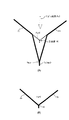
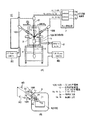
図2(A)に、この噴射ガス流Gの流速Fuを変更可能な本実施例の場合のプラズマアーク中心軸の基本形状を模式的に示す。また、図2(B)に比較例としてガス噴射を行わない場合(流速Fu=0)のプラズマアーク中心軸の基本形状を模式的に示す。
ガス噴射を行わない図2(B)の場合、2つのプラズマアークAaとAbとの合流部P付近での加熱処理を前提とし、このため、いわゆるV字アークと称される。
これに対し、図2(A)に示すように、本例ではガス流速Fuをゼロより大きく、最大流速Fu(max)以下の範囲で調整できる。したがって、プラズマアークAaとAbとの合流点がP0(破線)からPmax(実線)の範囲で変化する。なお、図示する実線と破線は、電子が存在しジュール加熱により超高温となるガス流(プラズマアーク)の中心線を示すが、実際のプラズマアークは太く長いことから、2本のプラズマアークがある程度近接する領域には、プラズマアークの周囲に電子は少ないが加熱された高温ガス流が存在する。したがって、プラズマアークの接触面積や位置、さらには、加熱された高温ガス流の接触面積の位置を被加熱物の処理したい部分に対しどのように設定するかに応じて加熱効率が変化する。本例では、被加熱物100の位置が固定の場合に、ガス流速Fuを変化させると、プラズマアークの接触面積や位置、その周囲の高温ガス流の接触面積や位置が変化する。これにより加熱状態が制御されるが、一般にガス流量を上げると、プラズマアークおよび高温ガス流の被加熱物100への接触面積が増えて入力可能なエネルギーも増加する。
FIG. 2A schematically shows the basic shape of the plasma arc central axis in the case of this embodiment in which the flow velocity Fu of the jet gas flow G can be changed. FIG. 2B schematically shows the basic shape of the central axis of the plasma arc when gas injection is not performed (flow velocity Fu = 0) as a comparative example.
In the case of FIG. 2B in which gas injection is not performed, it is assumed that heat treatment is performed in the vicinity of the junction P between the two plasma arcs Aa and Ab, and is therefore referred to as a so-called V-shaped arc.
On the other hand, as shown in FIG. 2 (A), in this example, the gas flow rate Fu can be adjusted within the range of greater than zero and less than or equal to the maximum flow rate Fu (max). Therefore, the confluence of plasma arcs Aa and Ab changes in the range from P0 (dashed line) to Pmax (solid line). The solid line and broken line shown in the figure indicate the center line of the gas flow (plasma arc) in which electrons are present and become extremely high temperature due to Joule heating. However, since the actual plasma arc is thick and long, the two plasma arcs have some extent. In the adjacent area, there is a heated hot gas stream around the plasma arc but with few electrons. Therefore, the heating efficiency varies depending on how the contact area and position of the plasma arc, and further, the position of the contact area of the heated high-temperature gas flow are set for the portion of the object to be heated. In this example, when the position of the object to be heated 100 is fixed and the gas flow rate Fu is changed, the contact area and position of the plasma arc and the contact area and position of the high-temperature gas flow around it change. Although the heating state is controlled by this, generally, when the gas flow rate is increased, the contact area of the plasma arc and the high-temperature gas flow with the object to be heated 100 increases, and the energy that can be input also increases.
図2(A)は、2つのノズル付き電極10A,10Bのそれぞれから吹き付けられるArまたはHeからなる保護ガス流Ga,Gbの流量Fa,Fbがほぼ同じ場合にも適用できる。ただし、2つのノズル付き電極10A,10Bからのガス流量を意図的に変えて、これによりプラズマアークの被加熱物への接触状態を変化させることもできる。
FIG. 2A can also be applied when the flow rates Fa and Fb of the protective gas flows Ga and Gb made of Ar or He sprayed from the two nozzle-equipped
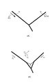
図3(A)は、ノズル付き電極10AからプラズマアークAaとともに出力される保護ガス流Gaの流速Faを、ノズル付き電極10BからプラズマアークAbとともに出力される保護ガス流Gbの流速Fbより十分大きくした場合の、プラズマアーク中心軸の基本形状を模式的に示す図である。
この場合、図2(B)の場合に比較して、プラズマアークの被加熱物への接触状態が変化する。このことから、この保護ガス流の流量比を制御する図1(A)に示すガス流量制御部7aと7bが、本発明の“加熱部制御手段”の一実施態様を構成する。さらに、ノズル20からの噴射ガス流量を制御する場合、ガス流量制御部7a〜7cが、本発明の“加熱部制御手段”の一実施態様を構成する。
FIG. 3A shows that the flow velocity Fa of the protective gas flow Ga output from the
In this case, the contact state of the plasma arc with the object to be heated changes compared to the case of FIG. Accordingly, the gas flow
なお、同じようにプラズマアークを斜めに変化させるためには、図3(B)に示すように、噴射ガス流Gを斜めから当てるようにしてもよい。
また、プラズマアークの被加熱物への接触状態を変化させるという意味では、被加熱物をプラズマアークに対して斜めにチルトさせる機構も採用できる。そのような機構は、ガス流量制御部7aと7b、あるいは、ガス流量制御部7a〜7cとともに、本発明の“加熱部制御手段”の一実施態様を構成する。
Similarly, in order to change the plasma arc diagonally, as shown in FIG. 3B, the injection gas flow G may be applied diagonally.
In addition, a mechanism for tilting the object to be heated obliquely with respect to the plasma arc can be employed in the sense that the contact state of the plasma arc with the object to be heated is changed. Such a mechanism, together with the gas flow
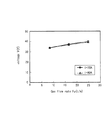
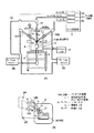
図4は、入力電流を一定とした場合に、ノズル20により真上からガスを吹き付ける流速(Gas flow rate)Fuを変化させたときの入力電圧値を測定し、グラフ化したものである。
このグラフから、ガス流速Fuを増大すると入力可能なエネルギーも増大していることが分かる。その結果、ガスの噴射によって加熱効率が向上するという効果が得られる。
FIG. 4 is a graph obtained by measuring the input voltage value when the flow rate Fu at which gas is blown from directly above by the
From this graph, it can be seen that the energy that can be input increases as the gas flow rate Fu increases. As a result, the effect that the heating efficiency is improved by gas injection is obtained.
前述したように、ノズル20から噴射するガスの種類は、アルゴンAr、ヘリウムHeなどの不活性ガスのほかに、たとえば酸素O2、窒素N2、あるいはアルゴンと窒素の混合ガス(Ar+N2)などの活性ガスであってもよい。ノズル20から活性ガスを噴射すると、その化学反応により被加熱物の処理が促進されるという利点がある。とくに窒素を入れると熱伝導率が大きくなり、化学反応が起きやすくなる。一方、ノズルから不活性ガスを噴射する場合は、電極の損耗への影響が小さく、その意味では好ましい。ガスの種類は、そのような利点を考慮して適宜決定される。
As described above, the type of gas ejected from the
また、ノズル20からガスを噴射すると、アーク接触状態の制御のほかに、いわゆるY字型のアーク形状が得やすいことから、処理面から発生する有害ガスを無害化するという意味でも好ましい作用がある。つまり、いわゆるV字型のアーク形状では、処理面から発生したガスがプラズマアークによって無害化される機会は少ないが、いわゆるY字型アーク形状の場合、相対的に、処理面から発生したガスがプラズマアークによって無害化される機会が増える。
なお、このような処理後のガスの無害化処理の効率を上げるために適した位置に、ガスの吸引口を設けるような変更も可能である。
また、Y字型のアークでは、被加熱物100の表面より深い箇所の加熱効率が高まり、段差のある物体の加熱が容易となる。
Further, when the gas is injected from the
In addition, it is possible to change such that a gas suction port is provided at a position suitable for increasing the efficiency of the gas detoxification process after such a process.
In addition, in the Y-shaped arc, the heating efficiency at a location deeper than the surface of the object to be heated 100 is increased, and heating of an object having a step becomes easy.
以下、本発明の実施の形態に係るプラズマ加熱装置の他の実施例を説明する。これらの実施例の説明では、先に説明した他の実施例と共通する構成は、同一符号を付して、その説明を省略する。 Hereinafter, other examples of the plasma heating apparatus according to the embodiment of the present invention will be described. In the description of these embodiments, the same reference numerals are given to configurations common to the other embodiments described above, and the description thereof is omitted.
[第2の実施例]
図5(A)は、第2の実施例に係るプラズマ加熱装置1Bの構成図である。また、図5(B)は、プラズマアークの発生状態および電圧関係を示す模式図である。なお、図5(B)は、被加熱物の処理面に対して斜めの位置からプラズマアークを発生させているが、その角度は任意であり、被加熱物の処理面に対して垂直にプラズマアークを当てることが可能である。
[Second Embodiment]
FIG. 5A is a configuration diagram of a plasma heating apparatus 1B according to the second embodiment. FIG. 5B is a schematic diagram showing a plasma arc generation state and a voltage relationship. In FIG. 5B, the plasma arc is generated from a position oblique to the processing surface of the object to be heated, but the angle is arbitrary, and the plasma is perpendicular to the processing surface of the object to be heated. It is possible to hit an arc.
第2の実施例の第1の実施例(図1参照)に対する第1の相違点は、ノズル20に代えて加熱部制御用の第3のノズル付き電極11を備えることである。この加熱部制御用のノズル付き電極11は、他の2つのノズル付き電極10Aと10Bと同様、電極とノズル枠体を備え、その隙間から噴射ガス流Guが出力可能な構成を有する。ここで噴射ガス流Guは、第1の実施例で述べた通常のガスからなる噴射ガス流Gを含み、さらに、電子を含む移行型の超高温ガス流(プラズマアーク)、電子を殆ど含まない非移行型の高温ガス流を含む広い概念である。この噴射ガス流Guの定義は、後述する第3〜第8の実施例にも適用される。
The first difference of the second embodiment from the first embodiment (see FIG. 1) is that a third nozzle-equipped
第2の実施例の第1の実施例に対する第2の相違点は、直流電源8Bが、2つのノズル付き電極10Aおよび10Bの各電極と、加熱部制御用のノズル付き電極11の電極との間に接続されていることである。ここでは、直流電源8Bの陽極(+)を2つのノズル付き電極10Aと10Bに共通に接続し、その陰極(−)を加熱部制御用のノズル付き電極11に接続している。
なお、第1の実施例と同様、陽極と陰極の接続関係を図5(A)および図5(B)の場合と入れ替えることが可能である。ただし、プラズマアークでは、陰極の電極に比べ陽極の電極が損耗しやすいことから、陽極側の電流を分流することができるという理由により、図5(A)および図5(B)に示すように、陽極数を陰極数より増やすほうが望ましい。このようにすると、1つの陽極側電極に流れる電流が分流数に比例して小さくなり、損耗しにくくなるという利点が得られる。
The second difference of the second embodiment from the first embodiment is that the
As in the first embodiment, the connection relationship between the anode and the cathode can be interchanged with the case of FIG. 5 (A) and FIG. 5 (B). However, in the plasma arc, since the anode electrode is more easily worn than the cathode electrode, the current on the anode side can be shunted as shown in FIGS. 5 (A) and 5 (B). It is more desirable to increase the number of anodes than the number of cathodes. In this way, there is an advantage that the current flowing through one anode side electrode becomes smaller in proportion to the number of shunts and is less likely to wear out.
このような構成のプラズマ加熱装置1Bにおいて、図5(B)に示すように、陽極側の2つのプラズマアークAaおよびAbと、加熱部制御用のノズル付き電極11から出力される陰極側のプラズマアークAuとにより電流経路が形成される。このため、プラズマアークの径自体が第1の実施例より太くなる。また、高温領域が保たれやすくなり、プラズマアークの解離や電離を加速させ、安定したY字アークが発生する。
これに加え、第1の実施例と同様に、噴射ガス流Guの流速Fu(および/または保護ガス流Ga,Gbの流速Fa,Fbの比)により、被加熱物へのアーク接触状態を制御する。このときプラズマアークが太い分、アーク接触面積を増大させて、より効率が高い加熱処理を実行することができる。
In the plasma heating apparatus 1B having such a configuration, as shown in FIG. 5 (B), two plasma arcs Aa and Ab on the anode side and plasma on the cathode side output from the
In addition to this, similarly to the first embodiment, the arc contact state to the object to be heated is controlled by the flow velocity Fu of the injection gas flow Gu (and / or the ratio of the flow rates Fa and Fb of the protective gas flows Ga and Gb). To do. At this time, since the plasma arc is thick, the arc contact area can be increased, and a heat treatment with higher efficiency can be executed.
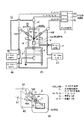
[第3の実施例]
図6(A)は、第3の実施例に係るプラズマ加熱装置1Cの構成図である。また、図6(B)は、プラズマアークの発生状態および電圧関係を示す模式図である。なお、図6(B)は、被加熱物の処理面に対して斜めの位置からプラズマアークを発生させているが、その角度は任意であり、被加熱物の処理面に対して垂直にプラズマアークを当てることも可能である。
[Third embodiment]
FIG. 6A is a configuration diagram of a
第3の実施例の第2の実施例(図5参照)に対する相違点は、加熱部制御用の第3のノズル付き電極11の電位を基準に、2つのノズル付き電極10Aと10Bに独立に直流電圧を印加する2つの直流電源8Cと8Dを備えることである。直流電源8Cの陽極(+)をノズル付き電極10Bに接続し、直流電源8Dの陽極(+)をノズル付き電極10Aに接続し、2つの直流電源8C,8Dの陰極(−)を加熱部制御用のノズル付き電極11に共通に接続している。なお、加熱部制御用のノズル付き電極11は、第2の実施例の場合と同様、電極とノズル枠体を備え、その隙間から噴射ガス流Guが出力可能な構成を有する。
The third embodiment differs from the second embodiment (see FIG. 5) in that the two nozzle-equipped
このような構成のプラズマ加熱装置1Cにおいて、図6(B)に示すように、陽極側の2つのプラズマアークAaおよびAbと、加熱部制御用のノズル付き電極11から出力される陰極側のプラズマアークAuとにより電流経路が形成される。その結果、第2の実施例と同様、プラズマアークが太い分、アーク接触面積が大きく、より効率が高い加熱処理を実行することができるという利点がある。
さらに、第3の実施例では、2つの直流電源8Cと8Dを有することから、電圧印加の自由度が高く、その分、よりアーク接触状態の制御性が向上するという利点がある。
In the
Furthermore, since the third embodiment has two
[第4の実施例]
図7(A)は、第4の実施例に係るプラズマ加熱装置1Dの構成図である。また、図7(B)は、プラズマアークの発生状態および電圧関係を示す模式図である。なお、図7(B)は、被加熱物の処理面に対して斜めの位置からプラズマアークを発生させているが、その角度は任意であり、被加熱物の処理面に対して垂直にプラズマアークを当てることが可能である。
[Fourth embodiment]
FIG. 7A is a configuration diagram of a plasma heating apparatus 1D according to the fourth embodiment. FIG. 7B is a schematic diagram showing a plasma arc generation state and a voltage relationship. Note that in FIG. 7B, the plasma arc is generated from a position oblique to the processing surface of the object to be heated, but the angle is arbitrary, and the plasma is perpendicular to the processing surface of the object to be heated. It is possible to hit an arc.
第4の実施例の第1の実施例(図1参照)に対する第1の相違点は、ノズル20に代えて加熱部制御用の第3のノズル付き電極11を備えることである。
また、第2の相違点は、直流電源8B以外の直流電源として、加熱部制御用のノズル付き電極11と坩堝5および被加熱物100との間に直流電圧を印加する直流電源8Eを備えることである。ここでは、直流電源8Eの陽極(+)を坩堝5および被加熱物100に接続し、その陰極(−)を加熱部制御用のノズル付き電極11に接続している。
このように被加熱物100に電圧を印加する構成では、被加熱物100がある程度高い導電性を有することが望ましい。ただし、導電性が低い場合でも、その電圧印加がアーク状態を多少とも安定させることに寄与するので、この加熱方法を有機物などの非導電性物質の加熱に適用することを排除するものではない。被加熱物100が導電性物質の場合、2つの直流電源8Aと8Eのそれぞれ、または、少なくとも一方で、陽極と陰極の接続関係を入れ替えることができる。また、被加熱物100が非導電性物質の場合、2つの直流電源8Aと8Eの双方で、陽極と陰極の接続関係を入れ替えることができる。
The first difference of the fourth embodiment from the first embodiment (see FIG. 1) is that a third nozzle-equipped
The second difference is that a
Thus, in the structure which applies a voltage to the to-
このような構成のプラズマ加熱装置1Bにおいて、図7(B)に示すように、2つのプラズマアークAaとAbの間、並びに、加熱部制御用のノズル付き電極11と被加熱物100との間に電流経路が形成される。その結果、第2,第3の実施例と同様、プラズマアークが太い分、アーク接触面積が大きく、より効率が高い加熱処理を実行することができるという利点がある。
さらに、第4の実施例では、2つの直流電源8Bと8Eを有することから、第3の実施例と同様に、電圧印加の自由度が高く、その分、よりアーク接触状態の制御性が向上するという利点がある。また、被加熱物100が電位的に固定可能であることからプラズマアークが安定するという利点がある。
In the plasma heating apparatus 1B having such a configuration, as shown in FIG. 7B, between the two plasma arcs Aa and Ab, and between the
Furthermore, since the fourth embodiment has two
[第5の実施例]
図8(A)は、第5の実施例に係るプラズマ加熱装置1Eの構成図である。また、図8(B)は、プラズマアークの発生状態および電圧関係を示す模式図である。なお、図8(B)は、被加熱物の処理面に対して斜めの位置からプラズマアークを発生させているが、その角度は任意であり、被加熱物の処理面に対して垂直にプラズマアークを当てることが可能である。
[Fifth embodiment]
FIG. 8A is a configuration diagram of a
第5の実施例の第4の実施例(図7参照)に対する相違点は、ノズル付き電極10Bに直流電圧を印加する直流電源8Aのほかに、ノズル付き電極10Aに直流電圧を印加する直流電源8Cを備えることである。直流電源8Aの陽極(+)をノズル付き電極10Bに接続し、直流電源8Cの陽極(+)をノズル付き電極10Aに接続し、2つの直流電源8A,8Cの陰極(−)を共通に接続している。第5の実施例は、この点で図6に示す第3の実施例と共通する。本実施例が第3の実施例と異なる点は、直流電源8A,8Cの陰極(−)を加熱部制御用のノズル付き電極11に接続しないで、第4の実施例の場合と同様、加熱部制御用のノズル付き電極11と坩堝5および被加熱物100との間に直流電圧を印加する直流電源8Eを備えることである。このようにすると、非導電物内に導電物が混在している場合でも、導電物に電流が流れやすくなることから、その確実な加熱処理が可能となる。
The fifth embodiment differs from the fourth embodiment (see FIG. 7) in that a DC power source that applies a DC voltage to the
このような構成のプラズマ加熱装置1Eにおいて、図8(B)に示すように、陽極側のプラズマアークAaと加熱部制御用のノズル付き電極11から出力される陰極側のプラズマアークAuとの間、陽極側のプラズマアークAbと陰極側のプラズマアークAuとの間、さらには、加熱部制御用のノズル付き電極11と被加熱物100との間に電流経路が形成される。その結果、第2〜第4の実施例と同様、プラズマアークが太い分、アーク接触面積が大きく、より効率が高い加熱処理を実行することができるという利点がある。
さらに、第5の実施例では、3つの直流電源8A,8Cおよび8Eを有することから、第4の実施例よりさらに電圧印加の自由度が高く、その分、よりアーク接触状態の制御性が向上するという利点がある。また、被加熱物100が電位的に固定可能であることからプラズマアークが安定するという利点がある。
In the
Furthermore, since the fifth embodiment has three
[第6〜第8の実施例]
前述した第1の実施例ではノズル20と2本のノズル付き電極10Aおよび10Bとを有し、上述した第2〜第5の実施例では3本のノズル付き電極10A,10Bおよび11を有するが、本実施の形態では、この3つの構成を1つの組として、当該組を複数設けることができる。この組の数に限定はないが、ここでは2組設けることを前提とした3つの実施例を述べる。
[Sixth to eighth embodiments]
The first embodiment described above has the
図9(A)〜図9(C)は、この3つの実施例において、プラズマアークの発生状態および電圧関係を示す模式図である。なお、ここでは、第1の実施例の場合の3つの構成、すなわちノズル20と2本のノズル付き電極10Aおよび10Bとを1つの組として、これを2組備える場合を例示するが、ノズル20は加熱部制御用のノズル付き電極11により代替可能である。その場合、第2〜第5の実施例で述べた電圧印加方法が、任意に適用可能である。また、上述した実施例で述べた変更は全て適用可能である。
FIG. 9A to FIG. 9C are schematic diagrams showing the plasma arc generation state and the voltage relationship in these three examples. Here, three configurations in the case of the first embodiment, that is, a case in which the
図9(A)に示す第6の実施例では、それぞれノズル20と2本のノズル付き電極10Aおよび10Bからなる組から出力されるプラズマアークを、被加熱物100の処理面に対して、それぞれ所定の角度で出力させ、これにより非常に広範な範囲でのプラズマ加熱処理を実現している。このとき、このプラズマアークの入射角度を変え、あるいは、噴射ガス流Guの流量、保護ガス流Gaの流量、保護ガス流Gbの流量の何れか1つまたは任意の組み合わせで複数の流量を制御することにより、被加熱物100に対するアーク接触状態を制御する。
In the sixth embodiment shown in FIG. 9 (A), the plasma arc output from the set of the
図9(B)に示す第7の実施例では、さらに被加熱物100にも電圧、ここでは陽極の電圧を印加している。これにより、第6の実施例と同様、非常に広範な範囲でのプラズマ加熱処理が可能であるとともに、アークが安定するという利点が得られる。
In the seventh embodiment shown in FIG. 9B, a voltage, here, an anode voltage is also applied to the
図9(C)に示す第8の実施例では、たとえば中央に、加熱部制御用のプラズマアークを出力するノズル付き電極12を設け、これを陰極とした電圧印加を行う。このときノズル付き電極12から出力する噴射ガス流Gucを制御すると、さらに制御パラメータが1つ増えることになり、より広範な範囲でのプラズマ加熱処理が可能となるという利益が得られる。ここで噴射ガス流Gucは、第1の実施例で述べた通常のガスからなる噴射ガス流Gを含み、さらに、電子を含む移行型の超高温ガス流(プラズマアーク)、電子を殆ど含まない非移行型の高温ガス流を含む広い概念である。
In the eighth embodiment shown in FIG. 9C, for example, a nozzle-equipped
以上述べてきた第1〜第8の実施例では、被加熱物100の加熱面積を制御できる、非加熱物の深い部分の加熱も可能である、被加熱物100の処理面から発生する有害ガスを無害化する機会が増えるなどの数々の利点があるほかに、直流電源は交流電源に比べ小型化が容易で、電力消費も少なくてすむ、さらにはアーク放電のスタートも容易である。
被加熱物100として産業廃棄物を処理する場合に、本発明の第1〜第8の実施例で述べたプラズマ加熱装置は、とくに医療産業廃棄物などのように雑固体廃棄物を処理するのに適している。医療産業廃棄物は、たとえば針などの導電物、たとえば、おむつ、プラスチック、ウイルスあるいは血液などの有機物、セラミックなどの様々な非導電物が混在する。そのような場合でも、導電物に適した加熱や、非導電物に適した加熱が有効かつ柔軟に行えるという利点がある。たとえば、図7のように、被加熱物100表面が非導電性物の場合は、2つのノズル付き電極10Aと10BからのプラズマアークAaとAbが電流経路となって、表面の非導電性物を溶かし、導電性物質が表面に現れると、その導電性物質を電流経路とするプラズマアークAuが機能してさらに加熱が進むことから、表面に現れる加熱対象の導電性に応じて効率がよい加熱を段階的に行うことができる。なお、表面に現れる加熱対象物の種類に応じて電源を切り換える制御も可能である。
In the first to eighth embodiments described above, the heating area of the object to be heated 100 can be controlled, and a deep portion of the non-heated object can be heated. In addition to numerous advantages such as increasing the chance of detoxification, the DC power supply is easier to miniaturize than the AC power supply, consumes less power, and is easier to start arc discharge.
When treating industrial waste as the object to be heated 100, the plasma heating apparatus described in the first to eighth embodiments of the present invention treats miscellaneous solid waste such as medical industrial waste. Suitable for Medical industrial waste includes a mixture of conductive materials such as needles, organic materials such as diapers, plastics, viruses or blood, and various non-conductive materials such as ceramics. Even in such a case, there is an advantage that heating suitable for a conductive material and heating suitable for a non-conductive material can be effectively and flexibly performed. For example, as shown in FIG. 7, when the surface of the object to be heated 100 is a non-conductive material, the plasma arcs Aa and Ab from the two
つぎに、上述した第1〜第8の実施例で採用可能なノズル付き電極の構造を説明する。
図10(A)と図10(B)は、本実施の形態で採用可能なノズル付き電極の構造図である。この構造は、2つのノズル付き電極10Aと10B、加熱部制御用のプラズマアーク11または12のいずれに対しても任意に適用できる。
Next, the structure of the electrode with nozzle that can be employed in the first to eighth embodiments described above will be described.
10A and 10B are structural diagrams of electrodes with nozzles that can be employed in this embodiment. This structure can be arbitrarily applied to any of the two
図10(A)に示すアーク構造は、熱伝導率が高い材料、たとえば銅からなる台座30に、たとえばハフニウム、ハフニウム合金、タングステンまたはタングステン合金からなる電極31が取り付けられた電極構造を有する。台座30には水冷用の水循環路が形成され、電極31の温度を冷やして損耗を防いでいる(間接冷却)。また、電極31に水循環路を設けることもできる(直接冷却)。電極構造の周囲に隙間をおいてノズル枠体32が形成され、これにより保護ガスまたは噴射ガス(以下、作動ガスと総称する)の通路が確保されている。ノズル本体32の先端部分は、アーク出力部分を残して閉じられており、これにより、雰囲気ガスが活性である場合に、その活性ガスによる電極の損耗を防いでいる。また、直流電流を流すことから安定したプラズマアークが生成される。このため図10(A)に示す電極構造をノズル閉鎖型と称する。なお、ノズル枠体32も間接冷却体として水循環路を備えてもよいし、そうでなくともよい。
The arc structure shown in FIG. 10A has an electrode structure in which an
これに対し、図10(B)に示す電極構造をノズル開放型と称する。
ノズル開放型電極構造では、ノズル枠体33の先端が開放された筒状になっている。このためタングステンまたはタングステン合金からなる棒状の電極34を、ノズル枠体33の開放端から外側に突出させて形成し、あるいは、棒状の電極34の先端をノズル枠体33内部空間から、外側の任意の長さまでスライド可能に構成することができる。この構成は、雰囲気ガスが活性でない場合に好適であるが、雰囲気ガスが活性の場合でも、電極34の長さを予め十分長く形成しておき、その先端が損耗すると、その分だけ電極34を外側にスライドさせて長期の使用に耐えられるようにできる。また、アーク発生後は、電極34の先端をノズル枠体34の内側に引っ込めて、電極34を保護することができる。さらに、作動ガスの圧力を下げて真空アークによる電極34のセルフクリーニングもできるなどの利点がある。
なお、ノズル枠体33の先端部分33Aは高沸点あるいは高抵抗の材料、たとえば炭素から形成され、これにより、この部分での不要なアーク放電を防止し、電極34が無駄に損耗し、さらにノズル枠体33やその先端部分33Aが損耗することを抑止している。また、この場合も、電極34を直接冷却する構成、ノズル枠体33や電極34に接触した不図示の部材を冷却して電極を間接的に冷却する構成のいずれか、または、両方の採用が可能である。
On the other hand, the electrode structure shown in FIG. 10B is referred to as a nozzle open type.
In the nozzle open-type electrode structure, the
The
ノズル開放型電極構造では電極34を外側に突出させた状態で電極34同士を接触させた状態、あるいは、この電極34を被加熱物100に直接接触した状態からプラズマアークの発生を開始させる接触アークスタートが可能である。また、電極34をスライドさせて、その先端同士を極力近づけた状態でパイロットアークを発生させ、このパイロットアークに基づいてプラズマアークを発生させることが可能である。そのため、交流電源型の場合に比べてプラズマアークの発生が容易である。なお、接触アークスタートでない場合でも、本発明では直流電源を用いていることから、インダクタを電極と電源との間に接続させると、より安定したプラズマアークを発生させることができる。
In the open nozzle electrode structure, a contact arc that starts the generation of a plasma arc from a state in which the
ところで、電極34を、タングステンを含む材料から構成すると、そのタングステンの組成率が低くても、比較的低温で莫大な紫外線や赤外線が出る。ノズル開放型電極構造では、この電極部34が長く、その周囲に作動ガスが均一に流れる。このため、電極34からの紫外線発光、赤外線発光および、タングステン蒸気による紫外線放射が可能である。とくに、作動ガスに窒素やヘリウムといったガスを混合させると、タングステン蒸気の放射量を増大させることができる。
紫外線は殺菌効果があるため、たとえば医療用廃棄物の処理時に殺菌を行うことができるという利点がある。また、赤外線により被加熱物を加熱する効果が得られ、加熱効率が高まるという利点がある。このため電極34にタングステンを含む材料から構成することが、より望ましい。これらのノズル付き電極構造、紫外線や赤外線を利用するための電極材料の選択は、前述した第1〜第8の実施例のいずれにおいても適用できる。
By the way, when the
Since ultraviolet rays have a sterilizing effect, there is an advantage that sterilization can be performed at the time of treatment of medical waste, for example. Moreover, the effect which heats a to-be-heated object with infrared rays is acquired, and there exists an advantage that a heating efficiency increases. For this reason, it is more desirable that the
前述した噴射ガス流の定義から明らかであるが、第1〜第8の実施例では、この電極構造の変更のほかに、噴射ガス流Gu,Gucを出力する加熱部制御用のノズル付き電極11,12を、非移行型に変更することができる。
非移行型のノズル付き電極(プラズマジェット)では、たとえば図10(A)に示すノズル閉鎖型の場合、ノズル32を電極材料から形成し、このノズルを陽極、電極31を陰極とする高温アーク放電がノズル内部で発生し、電子が殆ど存在しない高温ガス流が作動ガスとともにノズル先端の開放部から出力される。このプラズマジェットからの高温ガス流により、ノズル付き電極10A,10Bが出力するプラズマアークAa,Abの高温領域を保つと同時に、その解離や電離を加速させ、安定したY字アークを発生させる効果が得られる。なお、この場合でも作動ガスによる被加熱物100に対するアーク接触状態の制御効果は、上述した実施例と変わらない。
As is apparent from the definition of the jet gas flow described above, in the first to eighth embodiments, in addition to the change in the electrode structure, the nozzle-equipped
In the case of a non-migration type electrode with a nozzle (plasma jet), for example, in the case of the nozzle closed type shown in FIG. 10A, a high-temperature arc discharge in which the
また、各直流電源8A〜8E内部または外部に、これらの電源の陽極、陰極の双方と、それに接続すべき各ノズル付き電極との間にインダクタを接続させてもよい。これにより、過渡的電流の増減(急激な電流値の変動)を抑え、安定したプラズマアークの発生が可能となる。
その他、本発明の趣旨を逸脱しない範囲で、種々の変更が可能である。
Moreover, you may connect an inductor inside each
In addition, various modifications can be made without departing from the spirit of the present invention.
1A〜1E…プラズマ加熱装置、3…チャンバー、5…坩堝、6…被加熱物への電圧印加のための電極、7…ガス供給部、7a〜7c…ガス流量制御部、8A〜8E…直流電源、10A,10B…ノズル付き電極、11,12…加熱部制御用のノズル付き電極、20…加熱部制御用のノズル、31,34…電極、32,33…ノズル枠体、Aa,Ab,Au…プラズマアーク、G,Gu,Guc…噴射ガス流、Ga,Gb…保護ガス流
DESCRIPTION OF
Claims (9)
複数のノズル付き電極の電極間またはノズル付き電極の電極と被加熱物との間に直流電圧を供給し、ノズル付き電極から直流電流の経路となる前記プラズマアークを出力させる直流電源と、
前記プラズマアークにガスまたは高温ガス流を噴射し、当該プラズマアークの被加熱物への接触状態を制御する加熱部制御手段と
を備えるプラズマ加熱装置。 A plasma heating apparatus that outputs a plasma arc, which is a high-temperature gas flow containing electrons, from one or a plurality of nozzle electrodes, and heats the plasma arc in contact with an object to be heated,
A DC power source for supplying a DC voltage between electrodes of a plurality of nozzle-equipped electrodes or between an electrode of a nozzle-equipped electrode and an object to be heated, and outputting the plasma arc serving as a DC current path from the nozzle-equipped electrode;
A plasma heating apparatus comprising: heating unit control means for injecting a gas or a high-temperature gas flow into the plasma arc and controlling a contact state of the plasma arc with an object to be heated.
請求項1に記載のプラズマ加熱装置。 The heating unit control means includes an electrode with a nozzle for heating unit control capable of outputting a high-temperature gas flow to the plasma arc, and jets a gas and / or a high-temperature gas flow from the electrode with a nozzle for heating unit control The plasma heating apparatus according to claim 1, wherein the contact state of the plasma arc with the object to be heated is controlled.
請求項2に記載のプラズマ加熱装置。 A plurality of nozzle-attached electrodes arranged in such a direction that the distance from each other becomes closer to the tip that outputs the plasma arc, and the nozzle-attached electrode for controlling the heating unit are provided as one set, and a plurality of such sets are provided. The plasma heating apparatus according to claim 2.
請求項3に記載のプラズマ加熱装置。 In addition to the electrodes with nozzles for controlling the heating sections of each set, the heating section control means is provided between each set and can output a high-temperature gas flow to the plasma arc output from each set of electrodes with nozzles Including other nozzle-equipped electrodes for controlling the heating section, jetting gas from the other nozzle-equipped electrodes for controlling the heating section, or outputting a high-temperature gas flow from the other nozzle-equipped electrodes for controlling the heating section The plasma heating apparatus according to claim 3, wherein the contact state of the plasma arc output from each set of electrode groups with nozzles to the object to be heated is controlled.
ガスを噴射可能なノズル付き電極またはノズルからなるガス噴射部と、
当該ガス噴射部から加熱部制御用に噴射するガスの単位時間当たりの流量を制御する第1のガス流量制御部と、
前記ノズル付き電極が、プラズマアークを出力する電極と当該電極の周囲にガスの通路となる隙間を形成するノズル枠体とを備えている場合に、当該ノズル付き電極から出力されるガスの単位時間当たりの流量を制御する第2のガス流量制御部と、
を含む請求項1に記載のプラズマ加熱装置。 The heating unit control means includes
A gas injection unit comprising an electrode with nozzle or nozzle capable of injecting gas;
A first gas flow rate control unit that controls a flow rate per unit time of gas injected from the gas injection unit for heating unit control;
When the electrode with nozzle includes an electrode that outputs a plasma arc and a nozzle frame that forms a gap serving as a gas passage around the electrode, a unit time of gas output from the electrode with nozzle A second gas flow rate control unit for controlling the flow rate per hit,
The plasma heating apparatus according to claim 1, comprising:
プラズマアークを出力する電極と、
当該電極の周囲にガスの通路となる隙間を形成するノズル枠体と、
電極の先端がノズル枠体の端面より内側の位置から外側の位置まで軸方向にスライド可能な電極のスライド機構と
を備える請求項1に記載のプラズマ加熱装置。 Among the nozzle-equipped electrodes that are equipped, the specific nozzle-equipped electrode that outputs a plasma arc serving as a direct current path is
An electrode that outputs a plasma arc;
A nozzle frame that forms a gap serving as a gas passage around the electrode;
The plasma heating apparatus according to claim 1, further comprising: an electrode sliding mechanism in which a tip of the electrode is slidable in an axial direction from an inner position to an outer position from an end face of the nozzle frame.
請求項6に記載のプラズマ加熱装置。 The electrode of the specific nozzle-equipped electrode is formed of an electrode material containing tungsten, and at least an end of the nozzle frame of the specific nozzle-equipped electrode is formed of carbon. Plasma heating device.
プラズマアークを出力する電極と、
当該電極の周囲にガスの通路となる隙間を形成するノズル枠体と、
電極の先端がノズル枠体の端面より内側の位置から外側の位置まで軸方向にスライド可能な電極のスライド機構と
を備えるノズル付き電極。 An electrode with a nozzle that outputs a plasma arc and contacts and heats the plasma arc to an object to be heated,
An electrode that outputs a plasma arc;
A nozzle frame that forms a gap serving as a gas passage around the electrode;
An electrode with a nozzle comprising: an electrode slide mechanism in which an electrode tip is slidable in an axial direction from an inner position to an outer position from an end face of a nozzle frame.
請求項8に記載のノズル付き電極。
The electrode with a nozzle according to claim 8, wherein the electrode of the electrode with a nozzle is formed from an electrode material containing tungsten, and at least an end portion of a nozzle frame of the electrode with a nozzle is formed from carbon.
Priority Applications (1)
| Application Number | Priority Date | Filing Date | Title |
|---|---|---|---|
| JP2004105130A JP2005293945A (en) | 2004-03-31 | 2004-03-31 | Plasma heating device, and electrode with nozzle |
Applications Claiming Priority (1)
| Application Number | Priority Date | Filing Date | Title |
|---|---|---|---|
| JP2004105130A JP2005293945A (en) | 2004-03-31 | 2004-03-31 | Plasma heating device, and electrode with nozzle |
Publications (1)
| Publication Number | Publication Date |
|---|---|
| JP2005293945A true JP2005293945A (en) | 2005-10-20 |
Family
ID=35326665
Family Applications (1)
| Application Number | Title | Priority Date | Filing Date |
|---|---|---|---|
| JP2004105130A Pending JP2005293945A (en) | 2004-03-31 | 2004-03-31 | Plasma heating device, and electrode with nozzle |
Country Status (1)
| Country | Link |
|---|---|
| JP (1) | JP2005293945A (en) |
Cited By (6)
| Publication number | Priority date | Publication date | Assignee | Title |
|---|---|---|---|---|
| JP2013512413A (en) * | 2009-12-16 | 2013-04-11 | ケーシーシー コーポレーション | Plasma arc torch position adjustment device |
| JP2014200755A (en) * | 2013-04-08 | 2014-10-27 | Global Energy Trade株式会社 | Water treatment method and water treatment apparatus |
| CN105830540A (en) * | 2013-12-11 | 2016-08-03 | 应用等离子体株式会社 | Plasma generating device |
| CN113484127A (en) * | 2021-06-18 | 2021-10-08 | 合肥原位科技有限公司 | Instantaneous ultra-high temperature vacuum platform device |
| CN117704783A (en) * | 2023-12-08 | 2024-03-15 | 北京碳源领航环保科技有限公司 | plasma heating furnace |
| CN117704347A (en) * | 2023-12-08 | 2024-03-15 | 北京碳源领航环保科技有限公司 | boiler system |
Citations (3)
| Publication number | Priority date | Publication date | Assignee | Title |
|---|---|---|---|---|
| JPS5118342A (en) * | 1974-06-07 | 1976-02-13 | Nat Res Dev | |
| JPS53119251A (en) * | 1977-03-28 | 1978-10-18 | Daido Steel Co Ltd | Method of forming plasma radiation surface and plasma torch |
| WO2002039791A1 (en) * | 2000-11-10 | 2002-05-16 | Apit Corp. S.A. | Atmospheric plasma method for treating sheet electricity conducting materials and device therefor |
-
2004
- 2004-03-31 JP JP2004105130A patent/JP2005293945A/en active Pending
Patent Citations (3)
| Publication number | Priority date | Publication date | Assignee | Title |
|---|---|---|---|---|
| JPS5118342A (en) * | 1974-06-07 | 1976-02-13 | Nat Res Dev | |
| JPS53119251A (en) * | 1977-03-28 | 1978-10-18 | Daido Steel Co Ltd | Method of forming plasma radiation surface and plasma torch |
| WO2002039791A1 (en) * | 2000-11-10 | 2002-05-16 | Apit Corp. S.A. | Atmospheric plasma method for treating sheet electricity conducting materials and device therefor |
Cited By (8)
| Publication number | Priority date | Publication date | Assignee | Title |
|---|---|---|---|---|
| JP2013512413A (en) * | 2009-12-16 | 2013-04-11 | ケーシーシー コーポレーション | Plasma arc torch position adjustment device |
| US8912463B2 (en) | 2009-12-16 | 2014-12-16 | Kcc Corporation | Plasma arc torch positioning apparatus |
| JP2014200755A (en) * | 2013-04-08 | 2014-10-27 | Global Energy Trade株式会社 | Water treatment method and water treatment apparatus |
| CN105830540A (en) * | 2013-12-11 | 2016-08-03 | 应用等离子体株式会社 | Plasma generating device |
| CN105830540B (en) * | 2013-12-11 | 2018-10-26 | 应用等离子体株式会社 | Plasma producing apparatus |
| CN113484127A (en) * | 2021-06-18 | 2021-10-08 | 合肥原位科技有限公司 | Instantaneous ultra-high temperature vacuum platform device |
| CN117704783A (en) * | 2023-12-08 | 2024-03-15 | 北京碳源领航环保科技有限公司 | plasma heating furnace |
| CN117704347A (en) * | 2023-12-08 | 2024-03-15 | 北京碳源领航环保科技有限公司 | boiler system |
Similar Documents
| Publication | Publication Date | Title |
|---|---|---|
| JP5226536B2 (en) | Transfer arc type plasma torch | |
| US5801489A (en) | Three-phase alternating current plasma generator | |
| Rutberg | Plasma pyrolysis of toxic waste | |
| KR100807806B1 (en) | DC arc plasmatron device and method of use | |
| US6215091B1 (en) | Plasma torch | |
| EP3277061B1 (en) | Plasma torch with structure capable of reversed polarity/straight polarity operation | |
| KR101111207B1 (en) | Apparatus for generating plasma | |
| KR101041026B1 (en) | Cavity Plasma Torch, Plasma / Gas Combustion Apparatus and Melting Method Using the Same | |
| US6781087B1 (en) | Three-phase plasma generator having adjustable electrodes | |
| CA1323670C (en) | Electric arc reactor | |
| JP3733461B2 (en) | Composite torch type plasma generation method and apparatus | |
| AU2015258742A1 (en) | Energy efficient high power plasma torch | |
| KR100568238B1 (en) | Plasma Hazardous Gas Treatment System | |
| JP2005293945A (en) | Plasma heating device, and electrode with nozzle | |
| CN214101883U (en) | Plasma torch | |
| WO2010095980A1 (en) | Dc electric arc plasmatron for apparatuses for plasma-processing solid waste | |
| KR20200090406A (en) | Thermal plasma processing apparatus | |
| KR100775995B1 (en) | Method for obtaining carbon black by pyrolysis by high temperature thermal plasma and reverse polarity cavity torch with gap for this | |
| Wang et al. | Production of long, laminar plasma jets at atmospheric pressure with multiple cathodes | |
| Shchitsyn et al. | Effect of polarity on the heat input into the nozzle of a plasma torch | |
| KR100253723B1 (en) | High-temperature DC plasma torch that increases the durability of the electrode by forming a vacuum atmosphere | |
| Anshakov et al. | Material processing using arc plasmatrons with thermochemical cathodes | |
| JPH04124445A (en) | Plasma jet generating method and plasma generator | |
| EP1258177A1 (en) | Three-phase plasma generator having adjustable electrodes | |
| JP2004156819A (en) | Plasma arc melting furnace |
Legal Events
| Date | Code | Title | Description |
|---|---|---|---|
| A621 | Written request for application examination |
Free format text: JAPANESE INTERMEDIATE CODE: A621 Effective date: 20070402 |
|
| A131 | Notification of reasons for refusal |
Free format text: JAPANESE INTERMEDIATE CODE: A131 Effective date: 20100406 |
|
| A521 | Written amendment |
Free format text: JAPANESE INTERMEDIATE CODE: A523 Effective date: 20100607 |
|
| A131 | Notification of reasons for refusal |
Free format text: JAPANESE INTERMEDIATE CODE: A131 Effective date: 20101005 |
|
| A521 | Written amendment |
Free format text: JAPANESE INTERMEDIATE CODE: A523 Effective date: 20101206 |
|
| A02 | Decision of refusal |
Free format text: JAPANESE INTERMEDIATE CODE: A02 Effective date: 20110405 |