JP2005293902A - Fuel cell separator and fuel cell - Google Patents
Fuel cell separator and fuel cell Download PDFInfo
- Publication number
- JP2005293902A JP2005293902A JP2004103989A JP2004103989A JP2005293902A JP 2005293902 A JP2005293902 A JP 2005293902A JP 2004103989 A JP2004103989 A JP 2004103989A JP 2004103989 A JP2004103989 A JP 2004103989A JP 2005293902 A JP2005293902 A JP 2005293902A
- Authority
- JP
- Japan
- Prior art keywords
- ribs
- rib
- fuel cell
- heat
- electrode assembly
- Prior art date
- Legal status (The legal status is an assumption and is not a legal conclusion. Google has not performed a legal analysis and makes no representation as to the accuracy of the status listed.)
- Pending
Links
Images
Classifications
-
- Y—GENERAL TAGGING OF NEW TECHNOLOGICAL DEVELOPMENTS; GENERAL TAGGING OF CROSS-SECTIONAL TECHNOLOGIES SPANNING OVER SEVERAL SECTIONS OF THE IPC; TECHNICAL SUBJECTS COVERED BY FORMER USPC CROSS-REFERENCE ART COLLECTIONS [XRACs] AND DIGESTS
- Y02—TECHNOLOGIES OR APPLICATIONS FOR MITIGATION OR ADAPTATION AGAINST CLIMATE CHANGE
- Y02E—REDUCTION OF GREENHOUSE GAS [GHG] EMISSIONS, RELATED TO ENERGY GENERATION, TRANSMISSION OR DISTRIBUTION
- Y02E60/00—Enabling technologies; Technologies with a potential or indirect contribution to GHG emissions mitigation
- Y02E60/30—Hydrogen technology
- Y02E60/50—Fuel cells
Landscapes
- Fuel Cell (AREA)
Abstract
Description
本発明は、燃料電池及び燃料電池用セパレータに係り、特に、固体高分子形燃料電池(PEFC)や直接メタノール形燃料電池(DMFC)など高分子電解質膜を備えた燃料電池及びこれを構成するのに好適な燃料電池用セパレータに関する。 The present invention relates to a fuel cell and a fuel cell separator, and more particularly, to a fuel cell including a polymer electrolyte membrane such as a solid polymer fuel cell (PEFC) and a direct methanol fuel cell (DMFC), and the same. It is related with the separator for fuel cells suitable for.
近年、水素と酸素の電気化学反応によって発電する燃料電池がエネルギー供給源として注目されている。イオン交換樹脂膜を含む燃料電池などでは一般に、高分子電解質であるイオン交換樹脂膜がアノード極とカソード極の両電極間に狭持された膜電極接合体に、さらに膜電極接合体の各電極との間に燃料(例えば水素ガス)を挿通する燃料流路(アノード側)と酸化剤ガスを挿通する酸化剤ガス流路(カソード側)とを形成するセパレータを設けて構成されている(例えば、特許文献1参照)。 In recent years, fuel cells that generate electricity by electrochemical reaction between hydrogen and oxygen have attracted attention as an energy supply source. In general, in a fuel cell including an ion exchange resin membrane, an ion exchange resin membrane as a polymer electrolyte is sandwiched between both electrodes of an anode electrode and a cathode electrode, and further each electrode of the membrane electrode assembly A separator that forms a fuel flow path (anode side) through which fuel (for example, hydrogen gas) is inserted and an oxidant gas flow path (cathode side) through which the oxidant gas is inserted is provided (for example, , See Patent Document 1).
燃料電池を発電運転させる場合、アノード側、カソード側にそれぞれ必要に応じて加湿された燃料、酸化剤ガスが供給されると、電気化学反応(電池反応)を起こさせて電気を取出すと共に、カソード側の酸化剤ガス流路には発電に伴なって水が生成される。このとき、電池反応による発熱で膜電極接合体は昇温するが、セパレータの熱伝達作用により冷却されて所定の温度域に保持され、通常の温度環境下では安定した発電性能が得られるように構成されている。 When a fuel cell is operated for power generation, if fuel and oxidant gas humidified as necessary are supplied to the anode side and the cathode side, respectively, an electrochemical reaction (cell reaction) is caused and electricity is taken out. Water is generated in the oxidant gas flow path on the side along with power generation. At this time, although the membrane electrode assembly is heated by heat generated by the battery reaction, it is cooled by the heat transfer action of the separator and held in a predetermined temperature range so that stable power generation performance can be obtained under a normal temperature environment. It is configured.
セパレータには、燃料流路等の流路をなす凹部が形成されるように凸状のリブが複数設けられている。セパレータに設けられたリブは、膜電極接合体を均一温度に保つために均等ピッチ(等間隔)で設けられるのが通例であり、発電効率を高めるためにリブの膜電極接合体への押付け圧も均一に高く設定されている。通常の発電運転時であれば、発電性能上、均等ピッチでリブ、つまり流路を形成するようにし、またリブの膜電極接合体への押付け圧を均一で高い設定として、膜電極接合体の温度領域を均一に保持して発電させる方が望ましい。 The separator is provided with a plurality of convex ribs so as to form a recess that forms a flow path such as a fuel flow path. The ribs provided on the separator are usually provided at equal pitches (equal intervals) in order to keep the membrane electrode assembly at a uniform temperature, and the pressing pressure of the ribs on the membrane electrode assembly to increase power generation efficiency Is also set uniformly high. During normal power generation operation, the ribs, that is, the flow paths are formed at a uniform pitch for power generation performance, and the pressing pressure of the ribs on the membrane electrode assembly is set to be uniform and high. It is desirable to generate electricity while keeping the temperature region uniform.
ところが、氷点下(0℃以下)の低温域で保持された場合、高分子電解質の内部や電極近傍に存在する水分が停止中に凍結して、再始動しようとする際に燃料や酸化剤ガスの拡散を阻害したり、高分子電解質でのイオン伝導率が低下する問題を生ずる。 However, if it is kept in a low temperature range below freezing point (below 0 ° C), the water present in the polymer electrolyte and in the vicinity of the electrode freezes during stoppage, and the fuel or oxidant gas is lost when trying to restart. There arises a problem that the diffusion is inhibited and the ionic conductivity in the polymer electrolyte is lowered.
燃料電池はそれ自体の熱容量が大きいために、氷点下から始動し充分な熱量を得て燃料電池全体を短時間で0℃以上にまで昇温するのは難しいため、このような低温域では燃料電池停止後に再起動できなかったり、起動できても発電効率が著しく損なわれてしまう。 Since the fuel cell itself has a large heat capacity, it is difficult to start from below freezing and obtain a sufficient amount of heat to raise the temperature of the entire fuel cell to 0 ° C or higher in a short time. Even if the system cannot be restarted after it has stopped, the power generation efficiency will be significantly impaired.
上記のような凍結による問題に対し、膜電極接合体のガス拡散層付近にヒータを設けて、凍結状態からの低温始動性を向上させる技術が提案されている(例えば、特許文献2参照)。しかし、新たにヒータを設けることは構成要素が増えるばかりか、ガス拡散層中への埋設技術やヒータ供給用と外部供給用とに電気の流れを分ける等の煩雑な作業が不可欠であり、コストや製造工数、構造の複雑化など点で現実的とはいい難い。 In order to solve the above-mentioned problem caused by freezing, a technique has been proposed in which a heater is provided in the vicinity of the gas diffusion layer of the membrane electrode assembly to improve the low-temperature startability from the frozen state (for example, see Patent Document 2). However, the provision of a new heater not only increases the number of components, but also requires complicated work such as embedding technology in the gas diffusion layer and dividing the flow of electricity between heater supply and external supply. It is difficult to say that it is realistic in terms of manufacturing man-hours and structural complexity.
以上のように、凍結を生じ易い低温環境下での始動性や発電性能に関わる技術についてはこれまで提案がなされているものの、現況では構造の複雑化やコスト、製造工数を損なわずに、凍結の可能性のある低温環境下での安定した始動性、発電性能を確保することが可能な技術については未だ確立されるまでには至っていない。特に電気自動車等に搭載して主たる電力供給源としようとするような場合には、想定されるあらゆる使用環境に対応した性能を備えていることが重要であり、0℃以下となる低温域での始動性、発電性能の更なる安定化が望まれていた。 As described above, although technologies related to startability and power generation performance in a low-temperature environment where freezing is likely to occur have been proposed so far, freezing is performed without compromising the structure, cost, and manufacturing man-hours. The technology that can ensure stable startability and power generation performance in a low-temperature environment that has the possibility of being not yet established. In particular, when it is intended to be installed in an electric vehicle or the like and used as a main power supply source, it is important to have performance corresponding to all assumed usage environments, and in a low temperature range of 0 ° C. or less. Therefore, further stabilization of startability and power generation performance has been desired.
本発明は、上記に鑑みなされたものであり、燃料電池の通常の発電性能を維持しつつ低温環境下での内部凍結を効果的に解消し、低温始動性を高めることができる燃料電池用セパレータ、及び通常の発電性能を維持しつつ低温環境下での内部凍結が効果的に解消され、低温始動性に優れた燃料電池を提供することを目的とし、該目的を達成することを本発明の課題とする。 The present invention has been made in view of the above, and is a fuel cell separator capable of effectively eliminating internal freezing in a low temperature environment and enhancing low temperature startability while maintaining the normal power generation performance of the fuel cell. The present invention aims to provide a fuel cell in which internal freezing in a low-temperature environment is effectively eliminated while maintaining normal power generation performance and is excellent in low-temperature startability. Let it be an issue.
上記目的を達成するために、第1の発明の燃料電池用セパレータは、膜電極接合体と対向する側に複数のリブを有し、複数のリブの一部を断熱体で構成したものである。 In order to achieve the above object, the fuel cell separator of the first invention has a plurality of ribs on the side facing the membrane electrode assembly, and a part of the plurality of ribs is constituted by a heat insulator. .
本明細書中において、リブはセパレータの凹凸状面において凸状に突出した凸部であり、リブとリブとの間の凹部は一般にリブ(凸部)先端が膜電極接合体(特に電極の表面)と当接した状態で燃料流路又は酸化剤ガス流路を構成する。 In the present specification, the rib is a convex portion protruding in a convex shape on the concave-convex surface of the separator, and the concave portion between the ribs is generally the tip of the rib (convex portion) generally at the membrane electrode assembly (especially the electrode surface). The fuel flow path or the oxidant gas flow path is configured in a state where it is in contact with ().
高分子電解質膜を備えた燃料電池は一般に、高分子電解質膜及びこれを狭持する電極対で構成された膜電極接合体、並びに該膜電極接合体をその電極対の各電極面で狭持すると共に、前記膜電極接合体と対向する側に複数のリブを有し、リブ先端を膜電極接合体に当接させて各電極面との間に燃料が通過する燃料流路と酸化ガスが通過する酸化ガス流路とを形成する一対のセパレータを備え、通常の発電運転時はこのセパレータの熱伝達により冷却されて膜電極接合体が略一定の温度域に保持されるように構成されるが、第1の発明において更に、冷却機能を担うセパレータの一部、具体的には膜電極接合体と対向する側に設けられた複数のリブの一部を断熱体で構成することで、低温環境下で発電運転を停止した場合に膜電極接合体の温度を部分的に高く保てるので、低温環境下での内部凍結を解消し、低温始動性を効果的に向上させることができる。しかも、断熱体を部分的に用いた構成とすることで、通常の発電運転時の発電性能を大きく損なうことがなく、低温始動性と通常運転時の発電効率との両立が可能となる。 A fuel cell having a polymer electrolyte membrane generally has a membrane electrode assembly composed of a polymer electrolyte membrane and an electrode pair sandwiching the polymer electrolyte membrane, and the membrane electrode assembly sandwiched between the electrode surfaces of the electrode pair. And a plurality of ribs on the side facing the membrane electrode assembly, a fuel flow path through which fuel passes between each electrode surface with the rib tip abutting against the membrane electrode assembly, and an oxidizing gas A pair of separators that form an oxidant gas passage that passes therethrough is configured to be cooled by heat transfer of the separators during normal power generation operation so that the membrane electrode assembly is maintained in a substantially constant temperature range. However, in the first invention, a part of the separator responsible for the cooling function, specifically, a part of the plurality of ribs provided on the side facing the membrane electrode assembly is constituted by a heat insulator, thereby reducing the temperature. Temperature of membrane electrode assembly when power generation operation is stopped under the environment Since partially kept high, to eliminate the internal freezing in a low temperature environment, it is possible to effectively improve the low-temperature startability. In addition, by using a configuration in which the heat insulator is partially used, the power generation performance during normal power generation operation is not significantly impaired, and both low-temperature startability and power generation efficiency during normal operation can be achieved.
すなわち、発熱反応である電池反応の継続に伴ない上昇する膜電極接合体の熱量を膜電極接合体の外部に逃がす熱伝達性を部分的に低下させる、つまり複数のリブの一部に代えて、通常の発電運転時の発熱が過度となって発電性能の低下を招来しない程度に部分的に熱伝達性の低い断熱体を設け、熱伝達性のセパレータ(即ちリブ)の膜電極接合体(特に電極の表面)との接触面積を小さくすることで簡易に構成することができる。 In other words, the heat transfer property for releasing the heat quantity of the membrane electrode assembly that rises as the battery reaction, which is an exothermic reaction, to the outside of the membrane electrode assembly is partially reduced, that is, instead of a part of the plurality of ribs. In addition, a heat insulator having a low heat transfer property is provided to such an extent that heat generation during normal power generation operation is excessive and does not cause a decrease in power generation performance, and a membrane electrode assembly of a heat transfer separator (ie, rib) ( In particular, it can be easily configured by reducing the contact area with the surface of the electrode.
第2の発明の燃料電池用セパレータは、膜電極接合体と対向する側に複数のリブを有し、複数のリブの一部を発熱体で構成したものである。複数のリブの一部に代え、通常の発電運転時の発熱が過度となって発電性能の低下を招来しないように冷却性が保持される程度に部分的に発熱体を設けることで、熱伝達性のセパレータ(即ちリブ)の膜電極接合体(特に電極の表面)との接触面積を小さくすると共に、昇温による保温状態が形成される構成としたものである。 The separator for a fuel cell of the second invention has a plurality of ribs on the side facing the membrane electrode assembly, and a part of the plurality of ribs is constituted by a heating element. In place of a part of the ribs, heat is transferred by providing a heating element partly to the extent that cooling performance is maintained so that heat generation during normal power generation operation is not excessive and deterioration of power generation performance is caused. The contact area between the conductive separator (i.e., rib) and the membrane electrode assembly (particularly the surface of the electrode) is reduced, and a heat retaining state is formed by raising the temperature.
すなわち、高分子電解質膜を有する燃料電池に構成した場合に、冷却機能を担うセパレータの一部、具体的には膜電極接合体と対向する側に設けられた複数のリブの一部を発熱体で構成することで、低温環境下で発電運転を停止するような場合に膜電極接合体の温度を部分的に高く保持できるので、低温環境下での内部凍結を解消でき、低温始動性を効果的に向上させることができ、しかも部分的に発熱体を用いて構成することで、通常の発電運転での発電性能を大きく損なうことがなく、低温始動性と通常運転時の発電効率との両立が可能となる。 That is, in the case of a fuel cell having a polymer electrolyte membrane, a part of the separator responsible for the cooling function, specifically, a part of the plurality of ribs provided on the side facing the membrane electrode assembly is used as the heating element. Because the membrane electrode assembly temperature can be kept partially high when power generation operation is stopped in a low-temperature environment, internal freezing in a low-temperature environment can be eliminated and low-temperature startability is effective. By using a heating element in part, the power generation performance in normal power generation operation is not significantly impaired, and both low-temperature startability and power generation efficiency during normal operation are compatible. Is possible.
上記の第1及び第2の発明の燃料電池用セパレータにおいて、断熱体又は発熱体は、リブとリブとの間隔を拡げてリブ間の凹部に断熱体又は発熱体を設けたり、あるいはリブの一部を断熱体又は発熱体に代えることで構成することができる。断熱体や発熱体は、セパレータに接着する等して設けることができる。 In the fuel cell separator according to the first and second inventions described above, the heat insulator or the heat generator is provided with a heat insulator or a heat generator in the recess between the ribs by widening the gap between the ribs, or one of the ribs. It can comprise by replacing a part with a heat insulating body or a heat generating body. The heat insulator and the heating element can be provided by bonding to a separator.
第3の発明の燃料電池用セパレータは、膜電極接合体と対向する側に複数のリブを有し、複数のリブを有する領域にリブとリブとの間隔が不等間隔な領域を設けて構成したものである。既述のように、セパレータは膜電極接合体(特に電極)と当接して外部に熱伝達して冷却する機能を有し、その熱伝達性はセパレータの膜電極接合体(特に電極)との接触面積に依存するため、例えば、複数のリブが所定間隔を有して設けられた領域内に部分的にリブとリブとの間隔が広い領域が存在するように構成(すなわち単位面積当たりのリブ数が少ない構成)する等、リブ間隔が均一でない不等間隔に構成することによって接触面積の低減が可能であり、低温環境下で発電運転を停止するような場合の熱伝達を抑え、膜電極接合体の温度を部分的に高く保持できる。これにより、低温環境下での内部凍結を解消でき、低温始動性を効果的に向上させることが可能であり、しかも部分的に熱伝達効率が低くなるようにリブ間隔を不等間隔にして構成することで、通常の発電運転での発電性能を大きく損なわずに、低温始動性と通常運転時の発電効率との両立が可能となる。 A separator for a fuel cell according to a third aspect of the invention has a plurality of ribs on the side facing the membrane electrode assembly, and a region having a plurality of ribs is provided with a region where the intervals between the ribs are not equal. It is a thing. As described above, the separator is in contact with the membrane electrode assembly (especially the electrode) and has a function of transferring heat to the outside and cooling it, and the heat transfer property between the separator and the membrane electrode assembly (especially the electrode). Since it depends on the contact area, for example, a configuration in which a region where a plurality of ribs are provided with a predetermined interval has a region where the interval between the ribs is partially wide exists (that is, ribs per unit area). It is possible to reduce the contact area by configuring non-uniform spacing between the ribs, such as a configuration with a small number of ribs), suppressing heat transfer when stopping power generation operation in a low temperature environment, and membrane electrodes The temperature of the joined body can be kept partially high. This makes it possible to eliminate internal freezing in a low-temperature environment, effectively improve low-temperature startability, and configure the rib intervals to be unequal to partially reduce heat transfer efficiency. By doing so, it is possible to achieve both low-temperature startability and power generation efficiency during normal operation without greatly impairing power generation performance during normal power generation operation.
リブとリブとの間隔が不等間隔な領域は、部分的にリブとリブとの間隔が広い領域が存在する構成とする以外に、個々のリブを膜電極接合体に向かって凸状に突出する方向を法線とする平面上のリブ断面の面積を小さくした形状に構成にしたり、凸状に突出する方向に徐々にリブ断面が小さくなる例えば円錐や角錐等の錐体形状にリブを構成する等、セパレータの膜電極接合体(特に電極)との接触面積が小さくなる構成とすることにより形成可能である。後者では、リブ数を変えない構成とすることが可能である。 The area where the distance between the ribs is unequal is set so that the area where the distance between the ribs is wide is partially present, and each rib protrudes convexly toward the membrane electrode assembly. The rib cross-section area on the plane with the normal direction as the normal direction is reduced, or the rib cross-section gradually decreases in the protruding direction. For example, the rib is formed into a cone shape such as a cone or a pyramid. For example, the separator can be formed by reducing the contact area with the membrane electrode assembly (particularly the electrode). In the latter case, the number of ribs can be changed.
第4の発明の燃料電池用セパレータは、膜電極接合体と対向する側に複数のリブを有し、複数のリブを有する領域にリブ高さの低い領域を含むように構成したものである。 The separator for a fuel cell according to a fourth aspect of the present invention is configured to have a plurality of ribs on the side facing the membrane electrode assembly and include a region having a low rib height in a region having the plurality of ribs.
セパレータの熱伝達性は、上記した接触面積以外に、セパレータ及び膜電極接合体(特に電極)間の接触抵抗にも依存するため、一般にはボルト等での締付けにより面圧が付与される。第4の発明においては、複数のリブを有する領域の一部を高さの低いリブで構成することによりボルト等での締め付けた時の締付け圧を部分的に低下させることで、接触抵抗の低下に伴なう熱伝達効率の低下を利用することができ、低温環境下で発電運転を停止するような場合の熱伝達を抑え、膜電極接合体の温度を部分的に高く保持できるので、低温環境下での内部凍結を解消でき、低温始動性を効果的に向上させることができる。しかも、リブ高さを部分的に変化させることで通常の発電運転での発電性能を大きく損なわずに、低温始動性と通常運転時の発電効率との両立が可能となる。 Since the heat transferability of the separator depends on the contact resistance between the separator and the membrane electrode assembly (particularly the electrode) in addition to the contact area described above, surface pressure is generally applied by tightening with a bolt or the like. In the fourth aspect of the invention, a part of the region having a plurality of ribs is constituted by a rib having a low height, so that the clamping pressure when partially tightened with a bolt or the like is partially reduced, thereby reducing the contact resistance. The lowering of heat transfer efficiency that accompanies the heat generation can be utilized, and heat transfer in the case where power generation operation is stopped in a low temperature environment can be suppressed, and the temperature of the membrane electrode assembly can be kept partially high. The internal freezing in the environment can be eliminated, and the low temperature startability can be effectively improved. In addition, by changing the rib height partially, it is possible to achieve both low-temperature startability and power generation efficiency during normal operation without significantly impairing power generation performance during normal power generation operation.
第4の発明において、リブ高さは、セパレータの凹凸状面で凸状に突出した凸部の長さ、つまり燃料電池を構成したときに膜電極接合体に向かって突出する方向の長さである。 In the fourth invention, the rib height is the length of the protrusion protruding in a convex shape on the uneven surface of the separator, that is, the length in the direction protruding toward the membrane electrode assembly when the fuel cell is formed. is there.
第5の発明の燃料電池用セパレータは、膜電極接合体と対向する側に複数のリブを有し、リブを有する側から反対側に至る領域の一部に断熱体を設けて構成したものである。セパレータのリブを複数有して燃料流路等の流路を形成する側(流路形成側)と反対側の一部、あるいは流路形成側からその反対側に至るセパレータ内部領域の一部に断熱体を設けることで、外部への熱伝達を抑えて膜電極接合体内に部分的に保温状態が形成され、低温環境下で発電運転を停止するような場合に膜電極接合体の温度を部分的に高く保持できるので、低温環境下での内部凍結を解消でき、低温始動性を効果的に向上させることができる。しかも、断熱体を部分的に設けることで、通常の発電運転での発電性能を大きく損なうことなく、低温始動性と通常運転時の発電効率との両立が可能である。 A fuel cell separator according to a fifth aspect of the invention comprises a plurality of ribs on the side facing the membrane electrode assembly, and a heat insulator provided in a part of the region from the side having the ribs to the opposite side. is there. A part on the side opposite to the side (flow path forming side) on which the flow path such as the fuel flow path is formed by having a plurality of separator ribs, or a part of the separator internal region extending from the flow path forming side to the opposite side By providing a heat insulator, the heat transfer to the outside is suppressed, a heat insulation state is partially formed in the membrane electrode assembly, and when the power generation operation is stopped in a low temperature environment, the temperature of the membrane electrode assembly is partially Therefore, it is possible to eliminate internal freezing in a low temperature environment and to effectively improve low temperature startability. In addition, by partially providing the heat insulator, it is possible to achieve both low temperature startability and power generation efficiency during normal operation without significantly impairing power generation performance during normal power generation operation.
第6の発明の燃料電池用セパレータは、膜電極接合体と対向する側に複数のリブを有し、リブを有する側から反対側に至る領域の一部に発熱体を設けて構成したものである。 The separator for a fuel cell according to a sixth aspect of the present invention comprises a plurality of ribs on the side facing the membrane electrode assembly, and a heating element provided in a part of the region from the side having the ribs to the opposite side. is there.
第6の発明は上記した第5の発明と同様に、セパレータのリブを複数有して燃料流路等の流路を形成する流路形成側と反対側の一部、あるいは流路形成側からその反対側に至るセパレータ内部領域の一部に発熱体を設けることで、低温環境下で発電運転を停止するような場合に膜電極接合体の温度を部分的に高く保持できるので、内部凍結を解消して、低温始動性を効果的に向上させることができる。また、発熱体を部分的に設けることで、通常の発電運転での発電性能を大きく損なうことなく、低温始動性と通常運転時の発電効率との両立が可能である。 As in the fifth aspect, the sixth aspect of the invention includes a part on the side opposite to the flow path forming side that has a plurality of ribs of the separator to form a flow path such as a fuel flow path, or from the flow path forming side. By providing a heating element in a part of the separator internal area that reaches the opposite side, it is possible to keep the temperature of the membrane electrode assembly partially high when power generation operation is stopped in a low temperature environment. This can be eliminated and the low temperature startability can be effectively improved. Further, by providing the heating element partially, it is possible to achieve both low temperature startability and power generation efficiency during normal operation without significantly impairing power generation performance during normal power generation operation.
第7の発明の燃料電池は、高分子電解質膜及び該高分子電解質膜を狭む電極対を含む膜電極接合体と、前記膜電極接合体を狭持する上記の第1ないし第6の発明のいずれか1つの燃料電池用セパレータとで構成したものである。 According to a seventh aspect of the present invention, there is provided a fuel cell comprising: a membrane electrode assembly including a polymer electrolyte membrane and an electrode pair for narrowing the polymer electrolyte membrane; and the first to sixth inventions holding the membrane electrode assembly. And any one of the fuel cell separators.
第7の発明においては、上記の第1ないし第6の発明のいずれか1つの燃料電池用セパレータを用いて構成されるので、低温環境下で発電運転を停止するような場合であっても膜電極接合体の温度を部分的に高く保持可能であり、低温環境下での内部凍結を解消して低温始動性を効果的に向上させることができる。しかもまた、通常の発電運転での発電性能を大きく損なうことなく、低温始動性及び通常運転時の発電効率の両方を確保することができる。 In the seventh invention, since the fuel cell separator according to any one of the first to sixth inventions described above is used, even if the power generation operation is stopped in a low temperature environment, the membrane The temperature of the electrode assembly can be kept partially high, and internal freezing in a low temperature environment can be eliminated to effectively improve low temperature startability. In addition, both low temperature startability and power generation efficiency during normal operation can be ensured without significantly impairing the power generation performance during normal power generation operation.
上記の第1ないし第6の発明に係る燃料電池、及び第7の発明の燃料電池には、固体高分子形燃料電池(PEFC)や直接メタノール形燃料電池(DMFC)などが含まれる。 The fuel cells according to the first to sixth inventions and the fuel cell of the seventh invention include a polymer electrolyte fuel cell (PEFC) and a direct methanol fuel cell (DMFC).
本発明によれば、燃料電池の通常の発電性能を維持しつつ低温環境下での内部凍結を効果的に解消し、低温始動性を高めることができる燃料電池用セパレータ、及び通常の発電性能を維持しつつ低温環境下での内部凍結が効果的に解消され、低温始動性に優れた燃料電池を提供することができる。 According to the present invention, it is possible to effectively eliminate internal freezing in a low temperature environment while maintaining the normal power generation performance of the fuel cell, and to improve the low temperature startability, and the normal power generation performance. It is possible to provide a fuel cell that effectively eliminates internal freezing in a low-temperature environment while maintaining it and has excellent low-temperature startability.
以下、図面を参照して、本発明の燃料電池の実施形態について詳細に説明すると共に、該説明を通じて本発明の燃料電池用セパレータの詳細についても具体的に説明する。なお、下記の実施形態において、発電運転に用いる燃料として水素ガスを、酸化剤ガスとして空気(酸素)を用いた固体高分子形燃料電池(PEFC)を中心に説明する。但し、本発明においては下記の実施形態に制限されるものではない。 Hereinafter, with reference to the drawings, embodiments of the fuel cell of the present invention will be described in detail, and details of the fuel cell separator of the present invention will also be specifically described through the description. In the following embodiment, a description will be given focusing on a polymer electrolyte fuel cell (PEFC) using hydrogen gas as a fuel used for power generation operation and air (oxygen) as an oxidant gas. However, the present invention is not limited to the following embodiment.
(第1実施形態)
本発明の燃料電池の第1実施形態を図1を参照して説明する。本実施形態は、セパレータの複数のリブが設けられた側(以下、この側をリブ面ともいう)の一部の領域においてリブとリブとの間隔(リブ間隔)を拡げ、部分的にセパレータ(リブ)と膜電極接合体との接触面積が小さくなるように構成したものである。
(First embodiment)
A first embodiment of the fuel cell of the present invention will be described with reference to FIG. In the present embodiment, the gap between the ribs (rib interval) is increased in a partial region on the side where the plurality of ribs of the separator are provided (hereinafter, this side is also referred to as a rib surface). Rib) and the membrane electrode assembly are configured to have a small contact area.
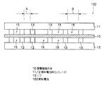
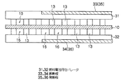
図1に示すように、本実施形態の燃料電池(単セル)100は、膜電極接合体10及び、膜電極接合体10を両側から狭持すると共に、燃料極(アノード極)側に水素ガスが通過する、すなわち給排される水素ガス流路15と酸化剤極(カソード極)側に空気(エア)が通過する、すなわち給排されるエア流路16とが形成されるようにリブ13が凸設された一対のセパレータ11,12で構成されている。
As shown in FIG. 1, a fuel cell (single cell) 100 according to this embodiment includes a
上記のように構成された単セルは、セパレータを介在させて複数積層することでスタック構造に構成することが可能であり、この場合には一つのセパレータが二つの膜電極接合体の間で共有され、セパレータの両側の面において流路が形成されるように構成することができる。 A single cell configured as described above can be formed into a stack structure by stacking a plurality of separators with a separator interposed therebetween. In this case, one separator is shared between two membrane electrode assemblies. The flow path can be formed on both sides of the separator.
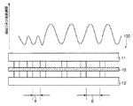
セパレータ11,12には各々、一方の側にリブ13が複数設けられたリブ面を有し、リブ面を膜電極接合体10に当接させたときに水素ガス、エアを給排する流路が形成されるようになっている。複数のリブが設けられたリブ面は、図1に示すように一部領域を除き、複数のリブがリブ間隔Aを有して規則的に配列されると共に、リブ面内の一部領域において部分的にリブ間隔が間隔Aより広いリブ間隔Bを有して配列されており、リブ面内のリブは部分的に不等間隔に設けられている。
Each of the
リブ間隔が間隔Bである領域は、リブ間隔が間隔Aである領域に比して単位面積当りの膜電極接合体とのリブ接触面積が小さく、セパレータ11,12による外部への熱伝達(冷却性)が小さくなる結果、図2に示すように、膜電極接合体10の温度をリブ間隔が間隔Bである領域で部分的に高く保つことが可能なようになっている。これにより、燃料電池全体としては通常の発電運転時の発電性能を大きく損なうことなく、低温環境下で発電運転を停止した場合などでの内部凍結が解消され、低温始動性を効果的に向上する。したがって、通常運転時の発電効率を確保しつつ、低温始動性をも向上させることが可能となる。
In the region where the rib interval is the interval B, the rib contact area with the membrane electrode assembly per unit area is smaller than the region where the rib interval is the interval A, and heat transfer (cooling) to the outside by the
リブ13のリブ間隔は、通常の発電運転時の発電性能を損なわず、所望とする条件下で凍結を回避して低温始動性を向上させ得る範囲で適宜選択すればよく、具体的な例として、狭い側の間隔Aが0.3mm〜1mmである場合に広い側の間隔Bを1.5mm〜5mmの範囲とし、かつ間隔Aの領域と間隔Bの領域との割合(A:B)を1:15〜2:3として構成することができる。なお、リブ間隔を拡げる場合、リブ間隔の上限としては10mm以下であるのが望ましい。
The rib interval of the
リブ13は、上記のようにリブ間隔を間隔A及び間隔Bの二つで構成する以外に、リブ間隔を3種以上異なるように適宜変えて構成することによって、例えば温度分布や間隔の分布を有するようにリブを設けるなど、所望の熱伝達率、すなわち所望のリブ接触面積とし所望の内部温度が保持されるように構成することができる。
The
具体的には、リブ間隔は、間隔A/間隔B/間隔C/間隔D…(A<B<C<D…)のように連続的に変化させることで、安定発電が可能な温度領域を広げることも可能である。また、リブ間隔を間隔Aと間隔Bとで構成する場合、例えば、間隔A/間隔A/間隔A/間隔B/間隔B/間隔B…などのブロック状の構成、あるいは間隔A/間隔B/間隔A/間隔B…や間隔A/間隔A/間隔A/間隔B/間隔A/間隔A/間隔A/間隔B…など、所望の形態で交互に変化させた構成とすることができる。 Specifically, the rib interval is continuously changed as an interval A / interval B / interval C / interval D (A <B <C <D. It can also be expanded. Further, when the rib interval is constituted by the interval A and the interval B, for example, a block-like configuration such as an interval A / interval A / interval A / interval B / interval B / interval B ... or an interval A / interval B / Interval A / interval B... Or interval A / interval A / interval A / interval B / interval A / interval A / interval A / interval B.
また、リブ間隔は、個々のリブの幅(リブ幅)を狭幅に構成することにより、あるいはリブ幅は所定の幅とし、リブの配置間隔を変化させることにより拡げ又は縮めることが可能である。 Further, the rib interval can be expanded or reduced by configuring the width of each rib (rib width) to be narrow, or by setting the rib width to a predetermined width and changing the arrangement interval of the ribs. .
セパレータ11及び12並びにリブ13は、ガス不透過の導電性部材、例えばカーボンを圧縮してガス不透過とした緻密質カーボンを用いて構成することができる。
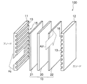
膜電極接合体10は、図3に示すように、フッ素系イオン交換樹脂膜20と、フッ素系イオン交換樹脂膜20を狭持するアノード極21及びカソード極22とで構成されている。フッ素系イオン交換樹脂膜20は、イオン導電性を有する高分子電解質で構成することができ、一般にパーフルオロスルホン酸膜などが用いられる。本実施形態では、ナフィオン膜(デュポン社製)で構成してある。この膜は、通常イオン導電性を高める点から湿潤状態とされ、水素ガスが供給されて得たアノード側の水素イオンは該膜を良好にイオン伝導してカソード側に移動することができる。この湿潤状態は、燃料である水素ガス及び/又はカソード側の酸素を含む空気に加水(加湿)することによって形成できる。
As shown in FIG. 3, the
アノード極21及びカソード極22は各々、図示しないが電気化学反応を担う触媒層と集電体として機能する拡散層とで構成されており、いずれにおいてもフッ素系イオン交換樹脂膜20側から順に触媒層と拡散層とが積層された構造に構成されている。各触媒層は、フッ素系イオン交換樹脂膜20の表面に、触媒としての白金又は白金と他の金属とからなる合金を塗布してなるものである。塗布は、白金又は白金と他の金属とからなる合金を担持したカーボン粉を作製し、このカーボン粉を適当な有機溶剤に分散させ、これに電解質溶液(例えば、Aldrich Chemical社、Nafion Solution)を適量添加してペースト化しスクリーン印刷する等の方法によって行なえる。また、カーボン粉を含有するペーストを膜成形したシートを高分子電解質膜上にプレスしたり、白金等を高分子電解質膜と対向する側の拡散層の表面に塗布するようにしてもよい。各拡散層は、ともに炭素繊維からなる糸で織成したカーボンクロスにより形成されている。なお、拡散層は、カーボンクロスのほか、炭素繊維からなるカーボンペーパーやカーボンフェルトなどで構成した形態も好適である。
Although not shown, each of the
燃料電池100では、図3に示すように、水素ガス流路15に水素(H2)密度の高い水素ガスが供給され、エア流路16に酸素(O2)を含む空気が供給されて、下記式(1)〜(3)で表される電気化学反応(電池反応)によって外部に電力を供給することができる。なお、式(1) 、式(2)は各々アノード側、カソード側での反応を示し、式(3)は燃料電池での全反応である。
In the
H2 → 2H++2e- …(1)
(1/2)O2+2H++2e- → H2O …(2)
H2+(1/2)O2 → H2O …(3)
H 2 → 2H + + 2e − (1)
(1/2) O 2 + 2H + + 2e − → H 2 O (2)
H 2 + (1/2) O 2 → H 2 O (3)
本実施形態では、図3に示すようにアノード側及びカソード側のリブを略平行に設けてあるが、例えばアノード側のリブとカソード側のリブとが略直行する等、アノード側及びカソード側には所望により選択した形態でリブを設けることが可能であり、所望の形態でリブが設けられたリブ面において上記構成とすることができる。 In the present embodiment, the anode side and cathode side ribs are provided substantially in parallel as shown in FIG. 3, but the anode side and cathode side ribs are substantially perpendicular, for example, on the anode side and cathode side. The rib can be provided in a form selected as desired, and the above-described configuration can be provided on the rib surface on which the rib is provided in a desired form.
(第2実施形態)
本発明の燃料電池の第2実施形態を図4を参照して説明する。本実施形態は、セパレータに設けられた複数のリブの一部を断熱性のリブで構成し、膜電極接合体の熱を外部に逃がす熱伝達性を部分的に低下させたものである。なお、発電のための燃料及び酸化剤ガスは第1実施形態で使用した燃料及び酸化剤ガスを用いることができ、第1実施形態と同様の構成要素には同一の参照符号を付してその詳細な説明を省略する。
(Second Embodiment)
A second embodiment of the fuel cell of the present invention will be described with reference to FIG. In the present embodiment, a part of the plurality of ribs provided in the separator is constituted by heat insulating ribs, and the heat transfer property for releasing the heat of the membrane electrode assembly to the outside is partially reduced. Note that the fuel and oxidant gas used in the first embodiment can be used as the fuel and oxidant gas for power generation, and the same reference numerals are given to the same components as those in the first embodiment, and Detailed description is omitted.
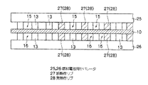
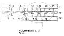
本実施形態では、図4に示すように、膜電極接合体10を両側から狭持すると共に、燃料極(アノード極)側に水素ガスが通過する、すなわち給排される水素ガス流路15と酸化剤極(カソード極)側に空気(エア)が通過する、すなわち給排されるエア流路16とが形成されるように伝熱性のリブ13と断熱性リブ27とが凸設されたセパレータ25,26を設けて構成されている。
In the present embodiment, as shown in FIG. 4, the
セパレータ25,26には各々、一方の側に伝熱性のリブ13と断熱性リブ27とがそれぞれ複数設けられたリブ面を有し、リブ面を膜電極接合体10に当接させたときに水素ガスを給排する水素ガス流路15及びエアを給排するエア流路16が形成されるようになっている。本実施形態では、リブ13及び断熱性リブ27が膜電極接合体10に当接して燃料電池を構成する。
Each of the
複数のリブが設けられたリブ面は、図4に示すように一部領域を除き、伝熱性のリブ13が複数所定のリブ間隔を有して規則的に凸設されると共に、リブ面内の一部領域だけ部分的に、伝熱性のリブ13と断熱性リブ27とが交互に規則的に凸設されており、リブ13及び断熱性リブ27が交互に配設された領域だけ部分的に膜電極接合体10の温度を高く保つことが可能なようになっている。断熱性リブ27は、リブ13とリブ13との間と同じ所定の間隔を有するように設けられており、リブ面内の全リブは等間隔となっている。
As shown in FIG. 4, the rib surface provided with a plurality of ribs is provided with a plurality of heat
リブ13及び断熱性リブ27が交互に配設された燃料電池の領域は、伝熱性のリブ13のみを有する領域に比して単位面積当りの外部への熱伝達(冷却性)が小さくなり、部分的に保温効果が得られ、結果的に低温環境下で発電運転を停止した場合等における内部凍結が解消され、低温始動性が効果的に向上する。低温環境下での内部凍結と発電効率を考慮して断熱性リブ27の形状、配設率を適宜選択し部分的に断熱性リブ27を設けるようにすることで、燃料電池全体として通常の発電運転時の発電性能を大きく損なうことなく、通常運転時の発電効率を確保しつつ、低温始動性をも向上させることが可能となる。
In the region of the fuel cell in which the
断熱性リブ27は、伝熱性のリブ13(セパレータ)との関係で熱伝導率の小さい材料を利用して任意の形状、サイズに構成することができ、例えば、樹脂やガラス等の公知材料から適宜選択して設けることが可能である。本実施形態では、セパレータ25及び26の膜電極接合体10と対向する側にリブ13と共に、断熱性リブ27を樹脂と接着材を用いてリブ13と同一形状に成形したものである。
The
断熱性リブ27は、上記のように部分的にリブ13と断熱性リブ27とが各々交互に位置するように配設する以外に、伝熱性のリブ13の膜電極接合体との接触面積や熱伝導率に応じ、例えば、リブ13(リフ゛13)と断熱性リブ27(リフ゛27)とを各々二つおき(リフ゛13/リフ゛13/リフ゛27/リフ゛27…)、各々三つおき等にして配設したり、複数(例えば三つ)のリブ13毎に一つの断熱性リブ27を配設する(例えば、リフ゛13/リフ゛13/リフ゛13/リフ゛27/リフ゛13/リフ゛13/リフ゛13/リフ゛27…)等、所望の形態で交互に変化させて、所望の熱伝達率、すなわち所望の内部温度が保持されるように構成することができる。
As described above, the
また、上記の伝熱性のリブ及び断熱性リブの幅(リブ幅)は、略同一とする以外に、例えば断熱性リブのリブ幅を広幅にして構成する等、異幅にして構成されていてもよい。さらに、伝熱性のリブと断熱性リブとを設けると共に、既述の第1実施形態の不等間隔とする形態を組合わせた構成とすることも効果的である。 Further, the width (rib width) of the heat conductive rib and the heat insulating rib is substantially the same, and the heat insulating rib is configured to have a different width, for example, a wide rib width of the heat insulating rib. Also good. Furthermore, it is also effective to provide a configuration in which heat transfer ribs and heat insulation ribs are provided, and a combination of the unequal intervals of the first embodiment described above is combined.
本実施形態では、複数のリブの一部だけ部分的に断熱性リブ(断熱体)で構成した場合を説明したが、一部のリブを断熱体で構成する以外に、発熱体で構成した形態も効果的である。すなわち、セパレータに設けられた複数のリブの一部を発熱性のリブで構成し、膜電極接合体を部分的に加温して大きく温度低下するのを防止し、内部温度を部分的に高めるようにした形態である。 In the present embodiment, a case has been described in which only a part of the plurality of ribs is partially constituted by heat insulating ribs (heat insulators). Is also effective. That is, a part of the plurality of ribs provided on the separator is made of exothermic ribs, and the membrane electrode assembly is partially heated to prevent a large temperature drop and partially increase the internal temperature. It is the form made like.
具体的には、既述した断熱性リブを発熱性リブに代えること以外は上記と同様にして構成することが可能であり、例えば図4に示すように、断熱性リブ27を発熱性リブ28に代えることによって構成できる。以下、さらに具体的に説明する。
Specifically, the
複数のリブが設けられたリブ面は、図4に示すように一部領域を除き、伝熱性のリブ13が複数所定のリブ間隔を有して規則的に凸設されると共に、リブ面内の一部領域だけ部分的に、伝熱性のリブ13と発熱性リブ28とが交互に規則的に凸設されおり、リブ13及び発熱性リブ28が交互に配設された領域だけ部分的に膜電極接合体10の温度を高く保つことが可能なようになっている。発熱性リブ28は、リブ13とリブ13との間と同じ所定の間隔を有するように設けられており、リブ面内の全リブは等間隔となっている。
As shown in FIG. 4, the rib surface provided with a plurality of ribs is provided with a plurality of heat
発熱性リブ28は、これを備えた燃料電池の電流回路と図示しない配線で電気的に接続されており、発電された電気を流すことにより発熱可能なようになっている。また場合により、他の外部電源からの電力供給によって発熱するように構成されてもよい。
The
また、発熱性リブによる加温は、発熱性リブに電気を流すか否か、すなわち凍結のおそれがあるか否かを判断し、凍結のおそれがあると判断されたときに燃料電池の電流回路と発熱性リブ28との接続を行なう切替スイッチ(不図示)を自動的に切替える切替手段(不図示)を設けて、凍結のおそれがある場合に選択的に電流を流すようにすることができる。
The heating by the exothermic rib determines whether electricity flows through the exothermic rib, that is, whether there is a possibility of freezing, and when it is determined that there is a possibility of freezing, the current circuit of the fuel cell By providing a switching means (not shown) for automatically switching a changeover switch (not shown) for connecting the
発熱性リブ28は、電気抵抗が比較的高い材料を利用して任意の形状、サイズに構成することができ、例えば、カーボン、樹脂、ニッケル、クロム、マンガン、鉄等の公知材料から適宜選択して設けることが可能である。特に電気抵抗が1Ω以上である材料が好適である。本実施形態では、セパレータ25及び26の膜電極接合体10と対向する側にリブ13と共に、発熱性リブ28を樹脂と接着材とを用いてリブ13と同一形状に成形したものである。
The
リブ13及び発熱性リブ28が交互に配設された燃料電池の領域は、伝熱性のリブ13のみを有する領域に比し、発熱性リブの構成材料が一般に低伝熱性であることから外部への熱伝達を抑止するだけでなく、例えば低温環境下で燃料電池の通常の発電運転を停止する場合に予めあるいは適宜、所望の温度域に加温された状態に保つことで膜電極接合体10の熱が外部に逃げるのを抑え、部分的に保温効果を得、結果的に低温環境下での内部凍結が解消され、低温始動性が効果的に向上する。低温環境下での内部凍結と発電効率を考慮して発熱性リブ28の形状、配設割合を適宜選択し部分的に発熱性リブ28を設けるようにすることで、燃料電池全体として通常の発電運転時の発電性能を大きく損なうことなく、断熱体で構成した場合と同様に、通常運転時の発電効率を確保しつつ低温始動性をも向上させることが可能である。
The area of the fuel cell in which the
なお、発熱性リブ28もまた断熱性リブ27の場合と同様に、既述のように部分的にリブ13と発熱性リブ28とが各々交互に位置するように配設するほか、伝熱性のリブ13の膜電極接合体との接触面積や熱伝導率に応じ、リブ13と発熱性リブ28とを各々二つおき、三つおき等にして配設したり、複数(例えば二つ)のリブ13毎に一つの発熱性リブ28を配設する等、低温環境下において膜電極接合体が部分的に所望の温度域に保持されるように構成できる。
As in the case of the heat-insulating
本実施形態では、伝熱性のリブ13と断熱性リブ27又は発熱性リブ28とを略同一形状として構成したが、適宜任意の構成とすることができ、リブ13に対し断熱性リブ27又は発熱性リブ28膜の断面積(膜電極接合体に向かって凸状に突出する方向を法線とする平面上のリブ断面の面積)を大きくする等、リブ13に対し断熱性リブ27又は発熱性リブ28膜の電極接合体(特に電極)との接触面積が大きくなる形状に構成するようにした形態も効果的である。
In the present embodiment, the heat
(第3実施形態)
本発明の燃料電池の第3実施形態を図5を参照して説明する。本実施形態は、セパレータの複数のリブが設けられた側(燃料流路等の流路形成側)と反対側(流路非形成側)の一部に断熱板を設け、膜電極接合体の熱を外部に逃がす熱伝達性が部分的に低くなるように構成したものである。なお、発電のための燃料及び酸化剤ガスは第1実施形態で使用した燃料及び酸化剤ガスを用いることができ、第1実施形態と同様の構成要素には同一の参照符号を付してその詳細な説明を省略する。
(Third embodiment)
A third embodiment of the fuel cell of the present invention will be described with reference to FIG. In this embodiment, a heat insulating plate is provided on a part of the separator (a flow path forming side such as a fuel flow path) provided on the side opposite to the flow path forming side (the flow path non-forming side). The heat transferability for releasing heat to the outside is partially reduced. Note that the fuel and oxidant gas used in the first embodiment can be used as the fuel and oxidant gas for power generation, and the same reference numerals are given to the same components as those in the first embodiment, and Detailed description is omitted.
本実施形態では、図5に示すように、膜電極接合体10を両側から狭持すると共に、燃料極(アノード極)側に水素ガスを給排する水素ガス流路15と酸化剤極(カソード極)側に空気(エア)を給排するエア流路16とが形成されるように複数のリブ13が凸設され、リブ13の凸設面と反対側に断熱板が設けられたセパレータ31,32を設けて構成されている。
In the present embodiment, as shown in FIG. 5, the
セパレータ31,32には各々、一方の側にリブ13が等間隔に複数設けられたリブ面を有し、リブ面を膜電極接合体10に当接させたときに水素ガスを給排する水素ガス流路15及びエアを給排するエア流路16が形成されるようになっている。本実施形態では、リブ13が膜電極接合体10と当接されて燃料電池を構成する。
Each of the
セパレータ31,32の各リブ面の反対側(流路非形成側)には、図5に示すように、矩形板状の断熱板33,34が、その一面がセパレータ31又は32の流路非形成側表面と同一平面をなすように複数枚埋め込むように設けられており、低温環境下において膜電極接合体10の熱が外部に逃げるのを部分的に抑え、断熱板33,34が設けられた膜電極接合体の領域において保温効果が得られるようになっている。これにより、低温環境下で通常の発電運転を停止するような場合に内部凍結を解消し得、低温始動性が効果的に向上する。
As shown in FIG. 5, rectangular plate-shaped
また、低温環境下での内部凍結と発電効率を考慮して断熱板33,34の形状、配設割合を適宜選択し部分的に断熱板を設けることで、燃料電池全体として通常の発電運転時の発電性能を大きく損なうことなく、通常運転時の発電効率を確保しながら低温始動性をも向上させることが可能である。
In addition, considering the internal freezing in a low temperature environment and the power generation efficiency, the shape and arrangement ratio of the
断熱板33,34の形状は、板状以外に、断面が矩形、円形、台形等の棒状やコイル状など、所望により適宜選択すればよく、板状に構成した場合のその厚み、板面の面積等は、セパレータ(リブを含む)の材質やリブの形状、数、そのほか発熱の程度(運転状況等)などに応じ、適宜選択することができる。
The shape of the
断熱板33,34を構成する材料としては、リブ13(セパレータ31,32)との関係で熱伝導率の小さい材料が好適であり、例えば、カーボン、樹脂、ニッケル、クロム、マンガン、鉄等の公知材料から適宜選択することが可能である。
As a material constituting the
本実施形態では、セパレータ31,32の各リブ面の反対側に断熱板を設けて構成した場合を説明したが、断熱板(断熱体)を用いた構成以外に、発熱板などの発熱体を用いて構成した形態も効果的である。すなわち、セパレータの複数のリブが設けられた側(燃料流路等の流路形成側)と反対側(流路非形成側)の一部に発熱板を設け、膜電極接合体内を部分的に保温し加温して大きく温度低下するのを防止し、内部温度を部分的に高めるようにした形態である。
In the present embodiment, the case where a heat insulating plate is provided on the opposite side of each rib surface of the
具体的には、既述した断熱板を発熱板に代えること以外は上記と同様にして構成することが可能であり、例えば図5に示すように、断熱板33,34を発熱板35,36に代えることによって構成できる。以下、さらに具体的に説明する。 Specifically, the heat insulating plate can be configured in the same manner as described above except that the heat insulating plate described above is replaced with a heat generating plate. For example, as shown in FIG. It can comprise by replacing with. More specific description will be given below.
セパレータ31,32の各リブ面の反対側(流路非形成側)には、図5に示すように、矩形板状の発熱板35,36が、その一面がセパレータ31又は32の流路非形成側表面と同一平面をなすように複数枚埋め込むように設けられており、低温環境下において膜電極接合体10の熱が外部に逃げるのを部分的に抑止するだけでなく、例えば低温環境下で燃料電池の通常の発電運転を停止するような場合に予めあるいは適宜、所望の温度域に加温された状態に保つことで膜電極接合体10の熱が外部に逃げるのを効果的に抑え、発熱板35,36が設けられた膜電極接合体の領域において保温効果が得られるようになっている。これにより、低温環境下で通常の発電運転を停止するような場合に内部凍結を解消し得、低温始動性が効果的に向上する。
On the opposite side of each rib surface of the
また、低温環境下での内部凍結と発電効率を考慮して発熱板の形状、配設割合を適宜選択し部分的に発熱板を設けることで、燃料電池全体として通常の発電運転時の発電性能を大きく損なうことなく、断熱板で構成した場合と同様に、通常運転時の発電効率を確保しつつ低温始動性をも向上させることが可能である。 In addition, considering the internal freezing and power generation efficiency in a low temperature environment, the heat generating plate shape and placement ratio are appropriately selected, and the heat generating plate is partially provided, so that the power generation performance during normal power generation operation as a whole fuel cell As is the case with the heat insulating plate, it is possible to improve the cold startability while ensuring the power generation efficiency during normal operation.
発熱板35,36は、これを備えた燃料電池の電流回路と図示しない配線で電気的に接続されており、発電された電気を流すことにより発熱可能なようになっている。また場合により、他の外部電源からの電力供給によって発熱するように構成されてもよい。
The
また、発熱板による加温は、発熱板に電気を流すか否か、すなわち凍結のおそれがあるか否かを判断し、凍結のおそれがあると判断されたときに燃料電池の電流回路と発熱板35,36との接続を行なう切替スイッチ(不図示)を自動的に切替える切替手段(不図示)を設けて、凍結のおそれがある場合に選択的に電流を流すようにすることができる。
In addition, the heating by the heating plate determines whether electricity flows through the heating plate, that is, whether there is a risk of freezing. When it is determined that there is a risk of freezing, the current circuit of the fuel cell and the heat generation are determined. A switching means (not shown) for automatically switching a selector switch (not shown) for connecting to the
発熱板35,36は、電気抵抗が比較的高い材料を利用して任意の形状、サイズに構成することができ、例えば、カーボン、樹脂、ニッケル、クロム、マンガン、鉄等の公知材料から適宜選択することが可能である。特に電気抵抗が1Ω以上である材料が好適である。
The
上記では、断熱板又は発熱板を、その一面がセパレータ31(又は32)の流路非形成側の表面と同一平面をなすようにセパレータ31,32の各リブ面の反対側に設けた場合を説明したが、セパレータの流路形成側からその反対側に至るセパレータ内部となる領域に部分的に、断熱板等の断熱体又は発熱板等の発熱体を完全に埋設した構成とするこもできる。
In the above, the case where the heat insulating plate or the heat generating plate is provided on the opposite side of each rib surface of the
また、本実施形態では断熱板(断熱体)又は発熱板(発熱体)をセパレータ31,32の両方に設けた場合を説明したが、セパレータの一方のみに断熱体又は発熱体を設けたり、セパレータの一方には断熱体を、他方には発熱体を設けるようにしてもよい。
Moreover, although the case where the heat insulating plate (heat insulating body) or the heat generating plate (heat generating body) is provided in both the
また更に、既述の第1実施形態の不等間隔とする形態、第2実施形態の断熱性リブ又は発熱性リブを設けた形態を組合わせた構成とすることも効果的である。 Furthermore, it is also effective to combine the form in which the above-described first embodiment has unequal intervals and the form in which the heat insulating ribs or heat generating ribs in the second embodiment are provided.
(第4実施形態)
本発明の燃料電池の第4実施形態を図6を参照して説明する。本実施形態は、セパレータの複数のリブが設けられたリブ面の一部の領域においてリブ高さを低くし、セパレータと膜電極接合体との間の接触抵抗が部分的に大きくなるように構成したものである。なお、発電のための燃料及び酸化剤ガスは第1実施形態で使用した燃料及び酸化剤ガスを用いることができ、第1実施形態と同様の構成要素には同一の参照符号を付してその詳細な説明を省略する。
(Fourth embodiment)
A fourth embodiment of the fuel cell of the present invention will be described with reference to FIG. In the present embodiment, the rib height is lowered in a partial region of the rib surface provided with the plurality of ribs of the separator, and the contact resistance between the separator and the membrane electrode assembly is partially increased. It is what. Note that the fuel and oxidant gas used in the first embodiment can be used as the fuel and oxidant gas for power generation, and the same reference numerals are given to the same components as those in the first embodiment, and Detailed description is omitted.
本実施形態では、図6に示すように、膜電極接合体10を両側から狭持すると共に、燃料極(アノード極)側に水素ガスを給排する水素ガス流路15と酸化剤極(カソード極)側に空気(エア)を給排するエア流路16とが形成されるようにリブ13及びリブ43が凸設された一対のセパレータ41,42を設けて構成されている。
In the present embodiment, as shown in FIG. 6, the
セパレータ41,42には各々、図6の破線枠Cに示すように、一方の側に所定の高さのリブ13とリブ13よりリブ高さの低いリブ43とがそれぞれ複数設けられたリブ面を有し、リブ面を膜電極接合体10に当接させたときに水素ガスを給排する水素ガス流路15及びエアを給排するエア流路16が形成されるようになっている。
Each of the
リブ43は、リブ高さ、すなわちリブ面において膜電極接合体に向かって凸状に突出する長さがリブ13より短く構成されており、リブ面の一部領域にのみ部分的に設けられて、最終的にボルト等で締め付けて燃料電池とした場合に、リブ43が設けられた一部領域において締付け圧(例えば、2MPa)が部分的に低下するようになっている。本実施形態では、リブ43のリブ高さは、リブ13の95%のリブ高さに構成してある。
The
リブ高さAのリブ及びこれより低いリブ高さa(A>a)の一種又は複数種のリブで構成される場合、リブ高さaはリブ高さAの80〜98%の範囲とするのが望ましい。 When the rib height A is composed of one or more ribs having a rib height A and a lower rib height a (A> a), the rib height a is in the range of 80 to 98% of the rib height A. Is desirable.
複数のリブが設けられたリブ面は、図6のようにリブ13及びリブ43の2種のリブでリブ高さが部分的に一段階変化するように構成する以外に、リブ高さを例えば膜電極接合体の各領域での温度域やその変化幅(すなわち熱伝導)等の違いに応じ、3種以上のリブで三段階以上に変化するように、あるいはリブ高さが連続的な分布を有して変化するように適宜構成することが可能であり、このような構成とすることで所望の熱伝達率、すなわち所望の内部温度が保持されるようにすることができる。また、リブ高さの低いリブ43で構成された領域のリブ面全体に占める面積率についても同様に、適宜選択して構成すればよい。
The rib surface provided with a plurality of ribs has a rib height of, for example, two types of
具体的な例として、リブ13が設けられた領域とリブ13より低いリブ43が設けられた領域との面積比(リフ゛13:リフ゛43)は9:1〜5:5の範囲で構成することができる。
As a specific example, the area ratio (rib 13 : rib 43 ) between the area where the
膜電極接合体及びセパレータ間などをはじめとする各構成要素間の接触抵抗を下げる観点から、一般にはボルト等で締付けて面圧が加えられるが、リブ高さの低いリブ43が設けられた一部領域ではリブ(セパレータ)及び膜電極接合体10間の締付け圧が緩和されるため、膜電極接合体及びセパレータ間の接触抵抗が上昇し、セパレータ側への熱伝達が抑えられる結果、膜電極接合体10の温度をリブ高さの低い領域だけ部分的に高く保つことが可能である。これにより、低温環境下で発電運転を停止した場合などでの内部凍結が解消され、低温始動性を効果的に向上し、通常運転時の発電効率を確保しつつ低温始動性をも向上させることが可能となる。なお、ボルト等による締付けは従前の方法によって行なえる。
From the viewpoint of reducing the contact resistance between each component including the membrane electrode assembly and the separator, surface pressure is generally applied by tightening with a bolt or the like, but one
上記の実施形態では、燃料電池として固体高分子形燃料電池を中心に説明したが、燃料ガスに代えメタノールを燃料とする直接メタノール形燃料電池(DMFC)についても同様に適用することができ、DMFCでは水素ガス流路(燃料流路)にメタノールが供給される。 In the above embodiment, the polymer electrolyte fuel cell has been mainly described as the fuel cell. However, the present invention can be similarly applied to a direct methanol fuel cell (DMFC) using methanol instead of fuel gas as a fuel cell. Then, methanol is supplied to the hydrogen gas passage (fuel passage).
また、本発明の燃料電池は、電気自動車等の車両や船舶、航空機等への電力供給源として好適に適用することができる。 In addition, the fuel cell of the present invention can be suitably applied as a power supply source for vehicles such as electric vehicles, ships, airplanes, and the like.
10…膜電極接合体
11,12,25,26,31,32,41,42…燃料電池用セパレータ
13,43…リブ
27…断熱性リブ
28…発熱性リブ
33…断熱板
35…発熱板
100…燃料電池
DESCRIPTION OF
Claims (7)
Priority Applications (1)
| Application Number | Priority Date | Filing Date | Title |
|---|---|---|---|
| JP2004103989A JP2005293902A (en) | 2004-03-31 | 2004-03-31 | Fuel cell separator and fuel cell |
Applications Claiming Priority (1)
| Application Number | Priority Date | Filing Date | Title |
|---|---|---|---|
| JP2004103989A JP2005293902A (en) | 2004-03-31 | 2004-03-31 | Fuel cell separator and fuel cell |
Publications (1)
| Publication Number | Publication Date |
|---|---|
| JP2005293902A true JP2005293902A (en) | 2005-10-20 |
Family
ID=35326624
Family Applications (1)
| Application Number | Title | Priority Date | Filing Date |
|---|---|---|---|
| JP2004103989A Pending JP2005293902A (en) | 2004-03-31 | 2004-03-31 | Fuel cell separator and fuel cell |
Country Status (1)
| Country | Link |
|---|---|
| JP (1) | JP2005293902A (en) |
Cited By (8)
| Publication number | Priority date | Publication date | Assignee | Title |
|---|---|---|---|---|
| JP2013026012A (en) * | 2011-07-21 | 2013-02-04 | Fujikura Ltd | Temperature controller of fuel cell |
| EP3145009A1 (en) * | 2015-09-21 | 2017-03-22 | Commissariat à l'énergie atomique et aux énergies alternatives | Determination of a spatial distribution of the electrical contact resistance of an electrochemical cell |
| EP3145010A1 (en) * | 2015-09-21 | 2017-03-22 | Commissariat à l'énergie atomique et aux énergies alternatives | Determination of a spatial distribution of an electricity production parameter of an electrochemical cell |
| JP2017183252A (en) * | 2016-03-31 | 2017-10-05 | 株式会社フジクラ | Fuel cell, fuel cell stack, fuel cell system, and bipolar plate |
| US10181612B2 (en) | 2015-09-21 | 2019-01-15 | Commissariat A L'energie Atomique Et Aux Energies Alternatives | Determination of a spatial distribution of the catalytic activity of an electrochemical-cell electrode |
| US10651483B2 (en) | 2015-09-21 | 2020-05-12 | Commissariat A L'energie Atomique Et Aux Energies Alternatives | Determination of a spatial distribution of the permeability of an electrochemical - cell electrode |
| CN112385065A (en) * | 2018-07-04 | 2021-02-19 | 上海旭济动力科技有限公司 | Fuel cell having fluid guide channel and method for manufacturing same |
| CN112740449A (en) * | 2018-08-10 | 2021-04-30 | Ess技术有限公司 | Method and system for manufacturing redox flow battery system through roll-to-roll process |
-
2004
- 2004-03-31 JP JP2004103989A patent/JP2005293902A/en active Pending
Cited By (15)
| Publication number | Priority date | Publication date | Assignee | Title |
|---|---|---|---|---|
| JP2013026012A (en) * | 2011-07-21 | 2013-02-04 | Fujikura Ltd | Temperature controller of fuel cell |
| US10162012B2 (en) | 2015-09-21 | 2018-12-25 | Commissariat A L'energie Atomique Et Aux Energies Alternatives | Determining of a spatial distribution of the electrical contact resistance of an electrochemical cell |
| US10686202B2 (en) | 2015-09-21 | 2020-06-16 | Commissariat A L'energie Atomique Et Aux Energies Alternatives | Determination of a spatial distribution of an electrical production parameter of an electrochemical cell |
| FR3041480A1 (en) * | 2015-09-21 | 2017-03-24 | Commissariat Energie Atomique | DETERMINATION OF A SPATIAL DISTRIBUTION OF THE ELECTRIC CONTACT RESISTANCE OF AN ELECTROCHEMICAL CELL |
| FR3041481A1 (en) * | 2015-09-21 | 2017-03-24 | Commissariat Energie Atomique | DETERMINATION OF A SPATIAL DISTRIBUTION OF A PARAMETER FOR THE ELECTRIC PRODUCTION OF AN ELECTROCHEMICAL CELL |
| EP3145010A1 (en) * | 2015-09-21 | 2017-03-22 | Commissariat à l'énergie atomique et aux énergies alternatives | Determination of a spatial distribution of an electricity production parameter of an electrochemical cell |
| EP3145009A1 (en) * | 2015-09-21 | 2017-03-22 | Commissariat à l'énergie atomique et aux énergies alternatives | Determination of a spatial distribution of the electrical contact resistance of an electrochemical cell |
| US10181612B2 (en) | 2015-09-21 | 2019-01-15 | Commissariat A L'energie Atomique Et Aux Energies Alternatives | Determination of a spatial distribution of the catalytic activity of an electrochemical-cell electrode |
| US10651483B2 (en) | 2015-09-21 | 2020-05-12 | Commissariat A L'energie Atomique Et Aux Energies Alternatives | Determination of a spatial distribution of the permeability of an electrochemical - cell electrode |
| JP2017183252A (en) * | 2016-03-31 | 2017-10-05 | 株式会社フジクラ | Fuel cell, fuel cell stack, fuel cell system, and bipolar plate |
| CN112385065A (en) * | 2018-07-04 | 2021-02-19 | 上海旭济动力科技有限公司 | Fuel cell having fluid guide channel and method for manufacturing same |
| CN112400246A (en) * | 2018-07-04 | 2021-02-23 | 上海旭济动力科技有限公司 | Fuel cell having fluid guide channel and method for manufacturing same |
| CN112740449A (en) * | 2018-08-10 | 2021-04-30 | Ess技术有限公司 | Method and system for manufacturing redox flow battery system through roll-to-roll process |
| EP3821490A4 (en) * | 2018-08-10 | 2022-01-26 | ESS Tech, Inc. | Methods and system for manufacturing a redox flow battery system by roll-to-roll processing |
| AU2019319954B2 (en) * | 2018-08-10 | 2024-09-05 | Ess Tech, Inc. | Methods and system for manufacturing a redox flow battery system by roll-to-roll processing |
Similar Documents
| Publication | Publication Date | Title |
|---|---|---|
| US8158294B2 (en) | Fuel cell system and method of operating fuel cell system | |
| JP4351431B2 (en) | Fuel cell stack | |
| CN101151755A (en) | The fuel cell | |
| CA2700901C (en) | Fuel cell stack with thermally insulating non-power-generating cells | |
| JP4051076B2 (en) | Polymer electrolyte fuel cell | |
| JP2005293902A (en) | Fuel cell separator and fuel cell | |
| WO2011064951A1 (en) | Direct-oxidation fuel cell system | |
| US8492043B2 (en) | Fuel cell, fuel cell system, and method for operating fuel cell | |
| JP4056550B2 (en) | Fuel cell | |
| JP2005353561A (en) | Fuel cell | |
| JP2006156288A (en) | Fuel cell and fuel cell manufacturing method | |
| KR20130027245A (en) | Separator for fuel cell and fuel cell stack with the same | |
| JP5434035B2 (en) | Fuel cell stack structure | |
| JP2009123446A (en) | Solid polymer fuel cell | |
| JP2007059187A (en) | Fuel cell | |
| JP3685039B2 (en) | Polymer electrolyte fuel cell system | |
| JP5136051B2 (en) | Fuel cell | |
| JPH06333581A (en) | Solid polymer electrolyte fuel cell | |
| JP4848824B2 (en) | Polymer electrolyte fuel cell | |
| JP2008198507A (en) | Membrane electrode assembly, fuel cell, and catalyst ink | |
| JPH06333582A (en) | Solid polyelectrolyte fuel cell | |
| KR101240977B1 (en) | Fuel cell stack being capable of controlling cooling water flow of end cell | |
| JP2010113959A (en) | Fuel cell stack | |
| JPH11312530A (en) | Solid polymer electrolyte fuel cell | |
| JP2005228523A (en) | Fuel cell |