JP2005293894A - Fuel container for fuel cell, fuel cell for pocket electrical equipment using it, and pocket electrical equipment - Google Patents
Fuel container for fuel cell, fuel cell for pocket electrical equipment using it, and pocket electrical equipment Download PDFInfo
- Publication number
- JP2005293894A JP2005293894A JP2004103664A JP2004103664A JP2005293894A JP 2005293894 A JP2005293894 A JP 2005293894A JP 2004103664 A JP2004103664 A JP 2004103664A JP 2004103664 A JP2004103664 A JP 2004103664A JP 2005293894 A JP2005293894 A JP 2005293894A
- Authority
- JP
- Japan
- Prior art keywords
- fuel
- liquid
- fuel cell
- liquid level
- container
- Prior art date
- Legal status (The legal status is an assumption and is not a legal conclusion. Google has not performed a legal analysis and makes no representation as to the accuracy of the status listed.)
- Pending
Links
- 239000000446 fuel Substances 0.000 title claims abstract description 598
- 239000007788 liquid Substances 0.000 claims abstract description 291
- 238000004364 calculation method Methods 0.000 claims description 71
- 238000001514 detection method Methods 0.000 claims description 26
- 239000007800 oxidant agent Substances 0.000 claims description 21
- 230000001590 oxidative effect Effects 0.000 claims description 19
- 238000011084 recovery Methods 0.000 claims description 8
- 210000004027 cell Anatomy 0.000 claims 29
- 210000005056 cell body Anatomy 0.000 claims 1
- OKKJLVBELUTLKV-UHFFFAOYSA-N Methanol Chemical compound OC OKKJLVBELUTLKV-UHFFFAOYSA-N 0.000 description 33
- 238000010586 diagram Methods 0.000 description 18
- LFQSCWFLJHTTHZ-UHFFFAOYSA-N Ethanol Chemical compound CCO LFQSCWFLJHTTHZ-UHFFFAOYSA-N 0.000 description 14
- 239000003054 catalyst Substances 0.000 description 12
- 229920006254 polymer film Polymers 0.000 description 11
- 238000005259 measurement Methods 0.000 description 10
- 238000000034 method Methods 0.000 description 10
- 239000000463 material Substances 0.000 description 9
- 239000012528 membrane Substances 0.000 description 9
- 239000007784 solid electrolyte Substances 0.000 description 9
- 238000009434 installation Methods 0.000 description 7
- 239000002699 waste material Substances 0.000 description 6
- XLYOFNOQVPJJNP-UHFFFAOYSA-N water Substances O XLYOFNOQVPJJNP-UHFFFAOYSA-N 0.000 description 6
- OKTJSMMVPCPJKN-UHFFFAOYSA-N Carbon Chemical compound [C] OKTJSMMVPCPJKN-UHFFFAOYSA-N 0.000 description 4
- 229910052799 carbon Inorganic materials 0.000 description 4
- HBBGRARXTFLTSG-UHFFFAOYSA-N Lithium ion Chemical compound [Li+] HBBGRARXTFLTSG-UHFFFAOYSA-N 0.000 description 3
- 239000002253 acid Substances 0.000 description 3
- 238000013500 data storage Methods 0.000 description 3
- 239000001257 hydrogen Substances 0.000 description 3
- 229910052739 hydrogen Inorganic materials 0.000 description 3
- -1 hydrogen ions Chemical class 0.000 description 3
- 229910001416 lithium ion Inorganic materials 0.000 description 3
- 229910052751 metal Inorganic materials 0.000 description 3
- 239000002184 metal Substances 0.000 description 3
- 238000005192 partition Methods 0.000 description 3
- 239000000758 substrate Substances 0.000 description 3
- LCGLNKUTAGEVQW-UHFFFAOYSA-N Dimethyl ether Chemical compound COC LCGLNKUTAGEVQW-UHFFFAOYSA-N 0.000 description 2
- 229920000181 Ethylene propylene rubber Polymers 0.000 description 2
- WSFSSNUMVMOOMR-UHFFFAOYSA-N Formaldehyde Chemical compound O=C WSFSSNUMVMOOMR-UHFFFAOYSA-N 0.000 description 2
- OAKJQQAXSVQMHS-UHFFFAOYSA-N Hydrazine Chemical compound NN OAKJQQAXSVQMHS-UHFFFAOYSA-N 0.000 description 2
- PXHVJJICTQNCMI-UHFFFAOYSA-N Nickel Chemical compound [Ni] PXHVJJICTQNCMI-UHFFFAOYSA-N 0.000 description 2
- KDLHZDBZIXYQEI-UHFFFAOYSA-N Palladium Chemical compound [Pd] KDLHZDBZIXYQEI-UHFFFAOYSA-N 0.000 description 2
- 235000014676 Phragmites communis Nutrition 0.000 description 2
- 239000007864 aqueous solution Substances 0.000 description 2
- 229920001577 copolymer Polymers 0.000 description 2
- 230000000694 effects Effects 0.000 description 2
- PCHJSUWPFVWCPO-UHFFFAOYSA-N gold Chemical compound [Au] PCHJSUWPFVWCPO-UHFFFAOYSA-N 0.000 description 2
- 229910052737 gold Inorganic materials 0.000 description 2
- 239000010931 gold Substances 0.000 description 2
- GPRLSGONYQIRFK-UHFFFAOYSA-N hydron Chemical compound [H+] GPRLSGONYQIRFK-UHFFFAOYSA-N 0.000 description 2
- BDAGIHXWWSANSR-UHFFFAOYSA-N methanoic acid Natural products OC=O BDAGIHXWWSANSR-UHFFFAOYSA-N 0.000 description 2
- BASFCYQUMIYNBI-UHFFFAOYSA-N platinum Chemical compound [Pt] BASFCYQUMIYNBI-UHFFFAOYSA-N 0.000 description 2
- 229920000642 polymer Polymers 0.000 description 2
- 229920005597 polymer membrane Polymers 0.000 description 2
- 230000036647 reaction Effects 0.000 description 2
- 238000007789 sealing Methods 0.000 description 2
- 229910052709 silver Inorganic materials 0.000 description 2
- 239000004332 silver Substances 0.000 description 2
- OSWFIVFLDKOXQC-UHFFFAOYSA-N 4-(3-methoxyphenyl)aniline Chemical compound COC1=CC=CC(C=2C=CC(N)=CC=2)=C1 OSWFIVFLDKOXQC-UHFFFAOYSA-N 0.000 description 1
- HRPVXLWXLXDGHG-UHFFFAOYSA-N Acrylamide Chemical compound NC(=O)C=C HRPVXLWXLXDGHG-UHFFFAOYSA-N 0.000 description 1
- MYMOFIZGZYHOMD-UHFFFAOYSA-N Dioxygen Chemical compound O=O MYMOFIZGZYHOMD-UHFFFAOYSA-N 0.000 description 1
- UFHFLCQGNIYNRP-UHFFFAOYSA-N Hydrogen Chemical compound [H][H] UFHFLCQGNIYNRP-UHFFFAOYSA-N 0.000 description 1
- WHXSMMKQMYFTQS-UHFFFAOYSA-N Lithium Chemical compound [Li] WHXSMMKQMYFTQS-UHFFFAOYSA-N 0.000 description 1
- NBIIXXVUZAFLBC-UHFFFAOYSA-N Phosphoric acid Chemical group OP(O)(O)=O NBIIXXVUZAFLBC-UHFFFAOYSA-N 0.000 description 1
- KJTLSVCANCCWHF-UHFFFAOYSA-N Ruthenium Chemical compound [Ru] KJTLSVCANCCWHF-UHFFFAOYSA-N 0.000 description 1
- BQCADISMDOOEFD-UHFFFAOYSA-N Silver Chemical compound [Ag] BQCADISMDOOEFD-UHFFFAOYSA-N 0.000 description 1
- 239000000853 adhesive Substances 0.000 description 1
- 230000001070 adhesive effect Effects 0.000 description 1
- 150000001298 alcohols Chemical class 0.000 description 1
- 239000003513 alkali Substances 0.000 description 1
- 229910045601 alloy Inorganic materials 0.000 description 1
- 239000000956 alloy Substances 0.000 description 1
- 125000003178 carboxy group Chemical group [H]OC(*)=O 0.000 description 1
- 229910017052 cobalt Inorganic materials 0.000 description 1
- 239000010941 cobalt Substances 0.000 description 1
- GUTLYIVDDKVIGB-UHFFFAOYSA-N cobalt atom Chemical compound [Co] GUTLYIVDDKVIGB-UHFFFAOYSA-N 0.000 description 1
- 239000000470 constituent Substances 0.000 description 1
- 229910001882 dioxygen Inorganic materials 0.000 description 1
- 229920001971 elastomer Polymers 0.000 description 1
- 239000000806 elastomer Substances 0.000 description 1
- HQQADJVZYDDRJT-UHFFFAOYSA-N ethene;prop-1-ene Chemical group C=C.CC=C HQQADJVZYDDRJT-UHFFFAOYSA-N 0.000 description 1
- 229920006248 expandable polystyrene Polymers 0.000 description 1
- 239000010419 fine particle Substances 0.000 description 1
- 239000006260 foam Substances 0.000 description 1
- 235000019253 formic acid Nutrition 0.000 description 1
- 239000002828 fuel tank Substances 0.000 description 1
- 239000010763 heavy fuel oil Substances 0.000 description 1
- 229930195733 hydrocarbon Natural products 0.000 description 1
- 150000002430 hydrocarbons Chemical class 0.000 description 1
- 150000002500 ions Chemical class 0.000 description 1
- 229910052741 iridium Inorganic materials 0.000 description 1
- GKOZUEZYRPOHIO-UHFFFAOYSA-N iridium atom Chemical compound [Ir] GKOZUEZYRPOHIO-UHFFFAOYSA-N 0.000 description 1
- 230000001678 irradiating effect Effects 0.000 description 1
- 229910052746 lanthanum Inorganic materials 0.000 description 1
- FZLIPJUXYLNCLC-UHFFFAOYSA-N lanthanum atom Chemical compound [La] FZLIPJUXYLNCLC-UHFFFAOYSA-N 0.000 description 1
- 229910052744 lithium Inorganic materials 0.000 description 1
- 239000000203 mixture Substances 0.000 description 1
- 229910052759 nickel Inorganic materials 0.000 description 1
- 230000003287 optical effect Effects 0.000 description 1
- 229920000620 organic polymer Polymers 0.000 description 1
- 239000003960 organic solvent Substances 0.000 description 1
- 229910052762 osmium Inorganic materials 0.000 description 1
- SYQBFIAQOQZEGI-UHFFFAOYSA-N osmium atom Chemical compound [Os] SYQBFIAQOQZEGI-UHFFFAOYSA-N 0.000 description 1
- 229910052763 palladium Inorganic materials 0.000 description 1
- 239000002245 particle Substances 0.000 description 1
- 230000002093 peripheral effect Effects 0.000 description 1
- 229910052697 platinum Inorganic materials 0.000 description 1
- 239000002861 polymer material Substances 0.000 description 1
- 238000002407 reforming Methods 0.000 description 1
- 229910052702 rhenium Inorganic materials 0.000 description 1
- WUAPFZMCVAUBPE-UHFFFAOYSA-N rhenium atom Chemical compound [Re] WUAPFZMCVAUBPE-UHFFFAOYSA-N 0.000 description 1
- 229910052703 rhodium Inorganic materials 0.000 description 1
- 239000010948 rhodium Substances 0.000 description 1
- MHOVAHRLVXNVSD-UHFFFAOYSA-N rhodium atom Chemical compound [Rh] MHOVAHRLVXNVSD-UHFFFAOYSA-N 0.000 description 1
- 229910052707 ruthenium Inorganic materials 0.000 description 1
- 229920002379 silicone rubber Polymers 0.000 description 1
- 239000004945 silicone rubber Substances 0.000 description 1
- 239000000243 solution Substances 0.000 description 1
- 229910052712 strontium Inorganic materials 0.000 description 1
- CIOAGBVUUVVLOB-UHFFFAOYSA-N strontium atom Chemical compound [Sr] CIOAGBVUUVVLOB-UHFFFAOYSA-N 0.000 description 1
- 239000000126 substance Substances 0.000 description 1
- 125000001174 sulfone group Chemical group 0.000 description 1
- 238000002834 transmittance Methods 0.000 description 1
- 239000004636 vulcanized rubber Substances 0.000 description 1
- 229910052727 yttrium Inorganic materials 0.000 description 1
- VWQVUPCCIRVNHF-UHFFFAOYSA-N yttrium atom Chemical compound [Y] VWQVUPCCIRVNHF-UHFFFAOYSA-N 0.000 description 1
Images


Classifications
-
- Y—GENERAL TAGGING OF NEW TECHNOLOGICAL DEVELOPMENTS; GENERAL TAGGING OF CROSS-SECTIONAL TECHNOLOGIES SPANNING OVER SEVERAL SECTIONS OF THE IPC; TECHNICAL SUBJECTS COVERED BY FORMER USPC CROSS-REFERENCE ART COLLECTIONS [XRACs] AND DIGESTS
- Y02—TECHNOLOGIES OR APPLICATIONS FOR MITIGATION OR ADAPTATION AGAINST CLIMATE CHANGE
- Y02E—REDUCTION OF GREENHOUSE GAS [GHG] EMISSIONS, RELATED TO ENERGY GENERATION, TRANSMISSION OR DISTRIBUTION
- Y02E60/00—Enabling technologies; Technologies with a potential or indirect contribution to GHG emissions mitigation
- Y02E60/30—Hydrogen technology
- Y02E60/50—Fuel cells
Landscapes
- Fuel Cell (AREA)
Abstract
Description
本発明は、燃料電池用燃料容器、それを用いた携帯電気機器用燃料電池、および携帯電気機器に関する。 The present invention relates to a fuel container for a fuel cell, a fuel cell for a portable electric device using the same, and a portable electric device.
近年の情報化社会の到来とともに、パーソナルコンピュータ等の電気機器で扱う情報量が飛躍的に増大し、それに伴い、電気機器の消費電力も著しく増加してきた。特に、携帯型の電気機器では、処理能力の増加に伴って消費電力の増加が問題となっている。現在、このような携帯型の電気機器では、一般的にリチウムイオン電池が電源として用いられているが、リチウムイオン電池のエネルギー密度は理論的な限界に近づいている。そのため、携帯型の電気機器の連続使用期間を延ばすために、CPUの駆動周波数を抑えて消費電力を低減しなければならないという制限があった。 With the advent of the information society in recent years, the amount of information handled by electrical devices such as personal computers has increased dramatically, and accordingly, the power consumption of electrical devices has also increased significantly. In particular, in portable electric devices, an increase in power consumption has become a problem as processing capacity increases. Currently, in such portable electric devices, lithium ion batteries are generally used as a power source, but the energy density of lithium ion batteries is approaching the theoretical limit. Therefore, in order to extend the continuous use period of the portable electric device, there is a limitation that the power consumption must be reduced by suppressing the CPU driving frequency.
このような状況の中で、リチウムイオン電池に変えて、エネルギー密度が大きく、エネルギー効率の高い燃料電池を電気機器の電源として用いることにより、携帯型の電気機器の連続使用期間が大幅に向上することが期待されている。 In such a situation, instead of using a lithium ion battery, a fuel cell having a high energy density and high energy efficiency is used as a power source of the electric device, so that the continuous use period of the portable electric device is greatly improved. It is expected that.
近年、安価で取り扱いの容易なメタノールを原料として、メタノールを改質して水素を生成させるメタノール改質型や、メタノールを燃料として直接利用する直接型の燃料電池の開発も盛んに行われている。直接型の燃料電池では、メタノール水溶液から水素イオンを得ることができるので、改質器等が不要になり、携帯型の電気機器へ適用することの利点が大きい。また、液体のメタノール水溶液を燃料とするため、エネルギー密度が非常に高いという特徴がある。 In recent years, development of a methanol reforming type in which methanol is reformed to produce hydrogen using cheap and easy-to-handle methanol and a direct type fuel cell using methanol directly as a fuel has been actively performed. . In the direct type fuel cell, hydrogen ions can be obtained from an aqueous methanol solution, so that a reformer or the like is not necessary, and there is a great advantage in applying to a portable electric device. Further, since a liquid methanol aqueous solution is used as a fuel, the energy density is very high.
ここで、携帯型の電気機器に対しては、電源の使用可能時間を知りたいという要請があった。このため、燃料電池を電源とする場合、燃料の残量を確実に把握することが求められていた。 Here, there has been a request for portable electric devices to know the usable time of the power source. For this reason, when the fuel cell is used as a power source, it is required to reliably grasp the remaining amount of fuel.
特許文献1には、液体燃料を収容する燃料容器を備える燃料電池が例示されている。この構成において、燃料容器を透明または半透明の材料で構成し、液体燃料に発泡スチロールの浮き材を添加することにより、液体燃料の残存量を確認することが示されている。
ところが、携帯型パーソナルコンピュータ等の携帯型の電気機器においては、機器を水平に設置した状態で使用されるとは限られない。傾斜した状態で設置されたり、使用されたりすると、液面の位置が変動する。このため、従来の構成では、燃料容器中に収容された液体燃料の残存量の正確な把握が困難であった。 However, portable electric devices such as portable personal computers are not always used with the devices installed horizontally. When installed or used in an inclined state, the position of the liquid level changes. For this reason, in the conventional configuration, it is difficult to accurately grasp the remaining amount of the liquid fuel accommodated in the fuel container.
一方、携帯型パーソナルコンピュータ等の携帯型の電気機器においては、前述のように、燃料カートリッジを含む燃料容器に残存する液体の残量、燃料カートリッジの交換時期、燃料電池の使用可能時間等を正確に把握することに対する要求は高い。 On the other hand, in a portable electric device such as a portable personal computer, as described above, the remaining amount of liquid remaining in the fuel container including the fuel cartridge, the replacement timing of the fuel cartridge, the usable time of the fuel cell, etc. are accurately determined. The demand for grasping is high.
本発明は上記事情に鑑みてなされたものであり、その目的は、携帯型の電気機器に設けられる燃料電池の液体燃料の残量を確実に把握する技術を提供することにある。 The present invention has been made in view of the above circumstances, and an object thereof is to provide a technique for reliably grasping the remaining amount of liquid fuel in a fuel cell provided in a portable electric device.
本発明によれば、携帯電気機器に適用される燃料電池の燃料極に供給する液体燃料を収容する燃料収容室と、前記燃料収容室内の複数箇所における前記液体燃料の液面の位置を検知する液面検知部と、前記液面検知部で検知された前記液面の位置から前記液体燃料の残量を算出する演算部と、を有することを特徴とする燃料電池用燃料容器が提供される。 According to the present invention, a fuel storage chamber that stores liquid fuel to be supplied to a fuel electrode of a fuel cell applied to a portable electrical device, and a position of a liquid level of the liquid fuel at a plurality of locations in the fuel storage chamber are detected. There is provided a fuel container for a fuel cell, comprising: a liquid level detection unit; and a calculation unit that calculates a remaining amount of the liquid fuel from a position of the liquid level detected by the liquid level detection unit. .
本発明に係る燃料電池用燃料容器は、液面検知部を有する。液面検知部は、燃料収容室内の複数箇所における液体燃料の液面の位置を検知する。このため、一箇所の液面を検知する場合に比べて正確な液面の位置の把握が可能となる。よって、燃料容器が傾斜した状態で使用されている場合や、液面が変動する状態で使用されている場合にも、燃料容器中の液体の残量を正確に把握することができる。 The fuel container for a fuel cell according to the present invention has a liquid level detection unit. The liquid level detection unit detects the position of the liquid level of the liquid fuel at a plurality of locations in the fuel storage chamber. For this reason, it becomes possible to grasp the position of the liquid level more accurately than in the case of detecting the liquid level at one place. Therefore, even when the fuel container is used in an inclined state or when the liquid level is changed, the remaining amount of the liquid in the fuel container can be accurately grasped.
本発明によれば、燃料極を有する燃料電池本体と、前記燃料極に供給される液体燃料が収容される燃料収容室を備える燃料容器と、前記燃料収容室内の複数箇所における前記液体燃料の液面の位置を検知する液面検知部と、前記液面検知部で検知された前記液面の位置から前記液体燃料の残量を算出する演算部と、を含むことを特徴とする携帯電気機器用燃料電池が提供される。 According to the present invention, a fuel cell main body having a fuel electrode, a fuel container including a fuel storage chamber in which liquid fuel supplied to the fuel electrode is stored, and the liquid fuel liquid at a plurality of locations in the fuel storage chamber A portable electric device comprising: a liquid level detection unit that detects a position of a surface; and a calculation unit that calculates a remaining amount of the liquid fuel from the position of the liquid level detected by the liquid level detection unit. A fuel cell is provided.
本発明に係る携帯電気機器用燃料電池は、燃料収容室内の複数箇所における液面の位置を液面検知部で検知し、検知された液面の位置から液体燃料の残量を算出する演算部を備える構成となっている。このため、一箇所の液面を検知する構成の燃料電池に比べて正確な液面の位置の把握が可能となる。よって、携帯電気機器用燃料電池が傾斜した状態で使用される場合や、液面が変動する状態で使用される場合においても、燃料容器中の液体の残量を正確に把握される構成となっている。 The fuel cell for portable electrical equipment according to the present invention detects the liquid level position at a plurality of locations in the fuel storage chamber by the liquid level detection unit, and calculates the remaining amount of liquid fuel from the detected liquid level position It is the composition provided with. For this reason, it becomes possible to accurately grasp the position of the liquid level as compared with the fuel cell configured to detect one liquid level. Therefore, even when the portable electric device fuel cell is used in an inclined state or when the liquid level is changed, the remaining amount of liquid in the fuel container can be accurately grasped. ing.
本発明によれば、燃料極を有する燃料電池本体と、前記燃料極に供給される液体燃料が収容される燃料容器と、を含み、前記燃料容器が前記燃料電池用燃料容器であることを特徴とする携帯電気機器用燃料電池が提供される。 According to the present invention, a fuel cell main body having a fuel electrode and a fuel container for storing liquid fuel supplied to the fuel electrode, wherein the fuel container is the fuel container for the fuel cell. A fuel cell for portable electrical equipment is provided.
本発明に係る携帯電気機器用燃料電池は、上述の燃料容器を含むため、傾斜面に設置されて使用された場合にも、液体燃料の残量、燃料の補充のタイミング、または燃料電池の使用可能時間等を確実に把握することが可能な構成となっている。 Since the fuel cell for portable electrical equipment according to the present invention includes the fuel container described above, even when installed on an inclined surface, the remaining amount of liquid fuel, the timing of fuel replenishment, or the use of the fuel cell It has a configuration in which the possible time and the like can be reliably grasped.
本発明において、前記液面検知部は、前記燃料収容室に設けられ、前記液面の位置を検知する3個以上の液面センサを含み、前記液面センサは、すべてが同一直線上に位置しないように設けられていてもよい。3個以上の液面センサが設けられており、これらが一直線上に位置しないため、各センサの設置位置における液面の位置に基づいて、燃料収容室の液面をさらに正確に決定することができる。このため、燃料容器が傾いている場合であっても、燃料収容室中の液体燃料の残量を確実に把握することができる。 In the present invention, the liquid level detection unit is provided in the fuel storage chamber, and includes three or more liquid level sensors for detecting the position of the liquid level, and the liquid level sensors are all located on the same straight line. It may be provided so that it does not. Since three or more liquid level sensors are provided, and these are not positioned on a straight line, the liquid level in the fuel storage chamber can be determined more accurately based on the position of the liquid level at the installation position of each sensor. it can. For this reason, even when the fuel container is tilted, the remaining amount of liquid fuel in the fuel storage chamber can be reliably grasped.
本発明において、前記液面検知部は、前記燃料収容室に設けられ、前記液面の位置を検知する2個以上の液面センサと、前記液面の傾斜状態を検知する傾斜センサと、を含んでもよい。傾斜センサにて液面の傾斜状態が検知されるため、これと2個以上の液面センサとを用いることにより、燃料容器が傾いている場合であっても、液面および液体燃料の残量を確実に把握することができる。なお本発明において、液面の傾斜状態とは、燃料容器を水平面に設置した際の液面からの傾斜角度を指す。 In the present invention, the liquid level detection unit is provided in the fuel storage chamber, and includes two or more liquid level sensors that detect the position of the liquid level, and an inclination sensor that detects an inclination state of the liquid level. May be included. Since the tilt sensor detects the tilt state of the liquid level, by using this and two or more liquid level sensors, the liquid level and the remaining amount of liquid fuel can be obtained even when the fuel container is tilted. Can be surely grasped. In the present invention, the inclined state of the liquid level refers to an angle of inclination from the liquid level when the fuel container is installed on a horizontal plane.
本発明において、前記液面検知部は、前記燃料収容室に設けられ、前記液面の位置を検知する液面センサと、前記液面の傾斜状態を検知する複数の傾斜センサと、を含んでもよい。複数の傾斜センサを有するため、これを用いて互いに平行でない2方向以上の傾斜状態を検知することができる。この傾斜状態と1箇所以上において液面センサで検知される液面の位置に関する情報とを組み合わせて用いることにより、液面が傾斜している場合であっても、液面の位置および液体燃料の残量を確実に把握することができる。 In the present invention, the liquid level detection unit may include a liquid level sensor that is provided in the fuel storage chamber and detects a position of the liquid level, and a plurality of inclination sensors that detect an inclination state of the liquid level. Good. Since it has a plurality of tilt sensors, it can be used to detect tilt states in two or more directions that are not parallel to each other. By using a combination of this tilted state and information on the position of the liquid level detected by the liquid level sensor at one or more locations, even if the liquid level is tilted, the position of the liquid level and the liquid fuel The remaining amount can be surely grasped.
本発明において、前記液面検知部は、磁性体を備え、前記液面に沿って移動するフロートと、前記フロートの位置を検知する磁気センサと、を有してもよい。液面に沿って移動するフロートの位置を磁気センサで検知することにより、液面の位置が変動しやすい場合でも、液面の位置を確実に検知することができる。 In this invention, the said liquid level detection part is provided with the magnetic body, and may have the float which moves along the said liquid level, and the magnetic sensor which detects the position of the said float. By detecting the position of the float moving along the liquid level with a magnetic sensor, the position of the liquid level can be reliably detected even when the position of the liquid level is likely to fluctuate.
本発明において、前記演算部で算出された前記残量を表示する表示部をさらに備える構成とすることができる。こうすることにより、燃料電池を使用する際に、使用者が、燃料容器内に収容された液体燃料の残量を把握することができる。 In this invention, it can be set as the structure further provided with the display part which displays the said residual amount calculated by the said calculating part. By doing so, when using the fuel cell, the user can grasp the remaining amount of the liquid fuel stored in the fuel container.
本発明において、前記演算部で算出された前記残量に基づき、前記燃料収容室から前記燃料電池への前記液体燃料の供給を制御する制御部をさらに備える構成とすることができる。こうすることにより、燃料電池の燃料極に供給される液体燃料の濃度または量を確実に制御することができる。このため、燃料電池が安定な出力を発揮できる構成とすることができる。 In this invention, it can be set as the structure further equipped with the control part which controls supply of the said liquid fuel from the said fuel storage chamber to the said fuel cell based on the said residual amount calculated by the said calculating part. By so doing, the concentration or amount of liquid fuel supplied to the fuel electrode of the fuel cell can be reliably controlled. For this reason, it can be set as the structure which a fuel cell can exhibit a stable output.
本発明の燃料電池用燃料容器において、前記燃料電池に着脱可能に設けられるカートリッジであってもよい。こうすることにより、カートリッジ内の液体燃料の残量、カートリッジ内の燃料の使用可能時間、またはカートリッジの交換時期等を把握することができる。 In the fuel container for a fuel cell according to the present invention, the cartridge may be detachably provided on the fuel cell. By doing so, it is possible to grasp the remaining amount of liquid fuel in the cartridge, the usable time of the fuel in the cartridge, the replacement time of the cartridge, and the like.
また、本発明の携帯電気機器用燃料電池において、前記液体燃料が収容され、当該携帯電気機器用燃料電池に着脱可能に設けられる燃料カートリッジと、前記燃料極または酸化剤極から排出される液体を回収する燃料回収部と、をさらに備え、前記燃料容器は、前記燃料カートリッジと前記燃料回収部とに連通する燃料混合槽であってもよい。このようにすれば、燃料混合槽中の液体燃料の液面を複数箇所で検知することができる。よって、燃料混合槽中の液体燃料の液量を確実に算出することができる。 Further, in the fuel cell for portable electric equipment according to the present invention, the liquid fuel is accommodated and the fuel cartridge provided detachably on the portable electric equipment fuel cell and the liquid discharged from the fuel electrode or the oxidant electrode are disposed. And a fuel collecting section that collects fuel, and the fuel container may be a fuel mixing tank that communicates with the fuel cartridge and the fuel collecting section. In this way, the liquid level of the liquid fuel in the fuel mixing tank can be detected at a plurality of locations. Therefore, the liquid amount of the liquid fuel in the fuel mixing tank can be reliably calculated.
また、本発明の携帯電気機器用燃料電池において、前記燃料容器は、前記液体燃料が収容され、当該携帯電気機器用燃料電池に着脱可能に設けられる燃料カートリッジであってもよい。このようにすれば、燃料カートリッジ中の液体燃料の液面を複数箇所で検知することができる。よって、燃料カートリッジ中の液体燃料の液量を確実に算出することができる。 Further, in the fuel cell for portable electric equipment of the present invention, the fuel container may be a fuel cartridge that contains the liquid fuel and is detachably provided on the fuel battery for portable electric equipment. In this way, the liquid level of the liquid fuel in the fuel cartridge can be detected at a plurality of locations. Therefore, the liquid amount of the liquid fuel in the fuel cartridge can be reliably calculated.
本発明において、前記燃料容器中の前記液体燃料の燃料成分濃度を測定する燃料濃度測定手段をさらに備えてもよい。こうすることにより、燃料濃度と液体の残量から、液体燃料中の燃料成分の量を算出することができる。 In the present invention, a fuel concentration measuring means for measuring a fuel component concentration of the liquid fuel in the fuel container may be further provided. By doing so, the amount of the fuel component in the liquid fuel can be calculated from the fuel concentration and the remaining amount of the liquid.
本発明において、前記演算部は、前記燃料容器中の前記液体燃料の前記残量および前記燃料成分濃度に基づき、当該携帯電気機器用燃料電池の使用可能時間を算出する構成とすることができる。こうすることにより、燃料電池を使用する際に、使用者が、燃料容器内に収容された燃料成分の残量または燃料電池の使用可能時間をさらに正確に把握することができる。また、燃料容器が燃料電池用燃料カートリッジの場合、カートリッジの交換時期を把握することができる。 In this invention, the said calculating part can be set as the structure which calculates the usable time of the said fuel cell for portable electric devices based on the said residual amount and the said fuel component density | concentration of the said liquid fuel in the said fuel container. Thus, when using the fuel cell, the user can more accurately grasp the remaining amount of the fuel component accommodated in the fuel container or the usable time of the fuel cell. Further, when the fuel container is a fuel cartridge for a fuel cell, it is possible to grasp the replacement timing of the cartridge.
本発明によれば、前記携帯電気機器用燃料電池を備えることを特徴とする携帯電気機器が提供される。本発明に係る携帯電気機器は、以上に説明した携帯電気機器用燃料電池を備えるため、傾斜面での使用時や、液面が変動しやすい状況で使用された場合にも、電源となる燃料電池の使用可能時間の使用可能時間を確実に把握可能な構成となっている。 According to the present invention, there is provided a portable electric device comprising the fuel cell for portable electric device. Since the portable electric device according to the present invention includes the fuel cell for portable electric devices described above, the fuel serving as a power source even when used on an inclined surface or when the liquid level is likely to fluctuate. It has a configuration that can reliably grasp the usable time of the battery usable time.
以上説明したように本発明によれば、燃料収容室内の複数箇所における液体燃料の液面の位置を検知する液面検知部と、液面検知部で検知された液面から液体燃料の残量を算出する演算部と、を設けることにより、携帯型の電気機器に設けられる燃料電池の液体燃料の残量を確実に把握する技術が実現される。 As described above, according to the present invention, the liquid level detection unit that detects the position of the liquid level of the liquid fuel at a plurality of locations in the fuel storage chamber, and the remaining amount of liquid fuel from the liquid level detected by the liquid level detection unit By providing the calculation unit for calculating the above, a technique for reliably grasping the remaining amount of liquid fuel in the fuel cell provided in the portable electric device is realized.
以下、本発明の実施形態について、図面を用いて説明する。なお、すべての図面において、共通する構成要素には同一の符号を付し、適宜説明を省略する。 Hereinafter, embodiments of the present invention will be described with reference to the drawings. In all the drawings, common constituent elements are denoted by the same reference numerals, and description thereof will be omitted as appropriate.
なお、以下の実施形態で説明する燃料電池の用途は特に限定されないが、たとえば携帯電話、ノート型等の携帯型パーソナルコンピュータ、PDA(Personal Digital Assistant)、各種カメラ、ナビゲーションシステム、ポータブル音楽再生プレーヤー等の小型電気機器に適切に用いられる。 The use of the fuel cell described in the following embodiments is not particularly limited. For example, a portable personal computer such as a mobile phone or a notebook type, a PDA (Personal Digital Assistant), various cameras, a navigation system, a portable music player, etc. Appropriately used for small electrical equipment.
(第一の実施形態)
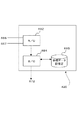
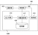
図17は、本実施形態に係る燃料容器の構成を示すブロック図である。図17に示した燃料容器424は、センサ群416および液量演算部417を含む。
(First embodiment)
FIG. 17 is a block diagram showing the configuration of the fuel container according to this embodiment. The
センサ群416は、燃料容器424中に収容された液体燃料の液面の位置を検知する複数のセンサから構成される。具体的には、3つのレベルセンサ402a、レベルセンサ402b、およびレベルセンサ402cを有する。これらのレベルセンサは燃料容器424の燃料収容室内に設けられ、燃料収容室内の3箇所における液面を検知する。
The
センサ群416にて検知された液面に関する情報は、各センサのセンサIDとともに、電気的信号として液量演算部417に入力される。液量演算部417は、センサ群416で検知された液面の位置に対応する電気的信号から、燃料収容室の液面の位置を求め、これに基づき燃料収容室内の液体燃料の残量を算出する。このとき、液量演算部417は、記憶部428の情報を参照する。
Information on the liquid level detected by the
記憶部428には、センサIDとセンサ設置位置座標との対応関係が記憶されている。また、記憶部428には、センサ群416で検知された電気的信号と、水面位置との対応関係が記憶されている。また、記憶部428には、燃料容器424の形状および体積に関する情報が、センサ設置位置座標および水面位置に対応づけて記憶されている。このため、記憶部428を参照することにより、液量演算部417は、センサ群416の位置と液面の水位を関連づけて求めることができる。液量演算部417液面の水位を3点について求めることができるため、これを用いて液面を決定することができる。よって、決定された液面と、記憶部428に記憶された燃料容器424の形状や体積に関する容器情報に基づき、燃料容器424中に収容された液体の量を算出することができる。
The
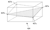
ここで、燃料容器424中の液体燃料の残量の算出方法の一例を具体的に示す。図22は、3つのレベルセンサを用いた残量算出方法を説明する図である。図22に示したように、ここでは、燃料容器424の形状が直方体である場合を例に説明する。また、レベルセンサ402a〜レベルセンサ402cの3つのレベルセンサは、互いに平行な直方体の3辺における液面427a〜液面427cの位置を検知するものとする。また、記憶部428には、各レベルセンサで得られる電気的信号と各辺における液面の位置の対応関係が記憶されている。
Here, an example of a method for calculating the remaining amount of liquid fuel in the
液量演算部417は、まず、レベルセンサ402a〜レベルセンサ402cからの電気的信号と、記憶部428に記憶された情報に基づき、それぞれの辺における液面の高さである液面427a〜液面427cを算出する。これより、液面427a〜液面427cは、レベルセンサ402a〜レベルセンサ402cが設けられた辺の長さに対する液面の高さの割合が求められる。そして、液面427a〜液面427cの位置より、レベルセンサが設けられた三辺に平行でレベルセンサを有しない辺における液面427dが求められる。このため、燃料容器424中の液体の液面が決定する。これより、燃料容器424の体積に対する液量の割合が求められる。このため、液量演算部417において、燃料容器424の液面の位置および液体の残量が算出される。
First, the liquid
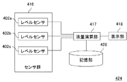
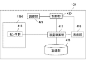
また、図18は、本実施形態に係る燃料容器424の別の構成を示すブロック図である。図18に示した燃料容器424は、図17の構成に加えて、さらに表示部418を有する。表示部418は、液量演算部417で算出された液体燃料の残量に関する情報を表示する。表示部418において、残量は、液量に応じて連続的に変化して表示される構成であってもよいし、所定の段階ごとに表示するように構成されていてもよい。
FIG. 18 is a block diagram showing another configuration of the
以下、図17または図18に示した構成の燃料容器を適用した燃料電池について説明する。 Hereinafter, a fuel cell to which the fuel container having the configuration shown in FIG. 17 or FIG. 18 is applied will be described.
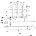
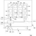
図1は、本実施形態に係る燃料電池を示す図である。図1の燃料電池400は、燃料電池本体100および燃料カートリッジ401を有する。燃料カートリッジ401は、燃料電池本体100に着脱可能に設けられ、改質器等を介さずに燃料電池本体100に直接供給される液体燃料を保持する容器である。なお、燃料カートリッジ401の詳細な構成については、第二の実施形態にて後述する。また、図1には示していないが、燃料電池本体100は、単セル構造101の酸化剤極における電池反応で生成する水をリザーバタンク1386に回収する酸化剤極側廃液回収管を有する。
FIG. 1 is a view showing a fuel cell according to the present embodiment. A
燃料電池本体100は、複数の単セル構造101、燃料容器811、仕切板853、燃料流出管1111、燃料回収管1113、ポンプ1117、リザーバタンク1386、レベルセンサ402、およびコネクタ1123を含む。なお、図1に示した3つのレベルセンサ402はいずれもリザーバタンク1386内に設けられている。この場合、リザーバタンク1386が、図17および図18における燃料容器424に対応する構成となっている。また、図1には示していないが、燃料電池400は、これらのレベルセンサ402で検知される信号に基づき液面の位置およびリザーバタンク1386中の液体燃料の残量を算出する液量演算部417および記憶部428を有し、図18に示した構成とする場合、表示部418をさらに有する。
The fuel cell
図1にもどり、燃料電池本体100において、燃料カートリッジ401に収容された液体燃料が燃料124として単セル構造101に供給される。燃料流出管1111には、ポンプ1117が設けられている。燃料容器811には、燃料流出管1111を経由して燃料124が供給される。燃料流出管1111は、リザーバタンク1386に連通している。燃料容器811に流入した燃料124は、燃料容器811内に設けられた複数の仕切板853に沿って流れ、複数の単セル構造101に順次供給される。
Returning to FIG. 1, in the fuel cell
単セル構造101に供給された燃料124のうち、電池反応に用いられなったものは、燃料回収管1113からリザーバタンク1386に回収される。回収された残存燃料は、リザーバタンク1386において、酸化剤極側廃液回収管から回収された水および燃料カートリッジ1361から供給される燃料124と混合された後、再び燃料流出管1111から燃料容器811に供給される。
Of the
なお、本実施形態および以下の実施形態において、燃料回収管1113および酸化剤極側廃液回収管からリザーバタンク1386に回収される液体を廃液と呼ぶ。廃液は、燃料極で電池反応に使用されなかった液体燃料を含む。また、廃液は、酸化剤極で生成する水を含む。
In this embodiment and the following embodiments, the liquid recovered from the
ポンプ1117として、たとえば消費電力が非常に小さい小型の圧電モーター等の圧電素子を用いることができる。また、図1には図示していないが、燃料電池400は、ポンプ1117の動作を制御する制御部を有することができる。
As the
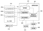
図23は、制御部を有する燃料電池本体100の構成の一例を示すブロック図である。図23に示した燃料電池本体100において、リザーバタンク1386の基本構成は、図18に示した燃料容器424の構成と同様である。図23においては、燃料電池本体100がさらに制御部430および調節部423を有する。
FIG. 23 is a block diagram showing an example of the configuration of the fuel cell
制御部430は、液量演算部417に接続し、液量演算部417で算出されたリザーバタンク1386中の液体燃料の残量に応じて調節部423の駆動を制御する。制御部430は、たとえば、CPU(Central Processing Unit)やIC(Integrated Circuit)とすることができる。制御部430は、予めプログラムされ、記憶装置(不図示)に記憶された手順に従って動作する構成とすることができる。また、制御部430は、リレーなどによるシーケンス回路とすることもできる。
The
調節部423は、リザーバタンク1386から単セル構造101への燃料124の供給または燃料カートリッジ401からリザーバタンク1386への液体燃料の供給を調節する調節部材である。たとえば図1に示した燃料電池400におけるポンプ1117に対応する。
The
なお、図23に示したように、制御部430が表示部418も制御する構成としてもよい。こうすれば、燃料の残量に応じて使用者に使用可能時間等をさらに確実に提示することができる。
Note that, as illustrated in FIG. 23, the
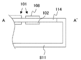
次に、燃料電池400に設けられた単セル構造101の構成を説明する。
図2は、図1のA−A'断面図である。単セル構造101は、燃料極102、酸化剤極108および固体電解質膜114を含む。燃料電池400においては、1枚の固体電解質膜114の一方の面に複数の燃料極102が設けられ、他方の面に複数の酸化剤極108が設けられている。対向する一組の燃料極102と酸化剤極108とで単セル構造101が構成される。このため、複数の単セル構造101が固体電解質膜114を共有し、同一の平面内に配置された構成となっている。
Next, the configuration of the
2 is a cross-sectional view taken along line AA ′ of FIG. The
固体電解質膜114は、燃料極102と酸化剤極108を隔てるとともに、両者の間で水素イオンを移動させる役割を有する。このため、固体電解質膜114は、水素イオンの伝導性が高い膜であることが好ましい。また、化学的に安定であって機械的強度が高いことが好ましい。固体電解質膜114を構成する材料としては、スルフォン基、リン酸基等の強酸基や、カルボキシル基等の弱酸基等の極性基を有する有機高分子材料が好ましく用いられる。
The
燃料極102および酸化剤極108は、それぞれ、触媒を担持した炭素粒子と固体電解質の微粒子とを含む燃料極側触媒層および酸化剤極側触媒層をそれぞれ基体上に形成した構成とすることができる。
Each of the
燃料極側触媒層の触媒としては、白金、金、銀、ルテニウム、ロジウム、パラジウム、オスミウム、イリジウム、コバルト、ニッケル、レニウム、リチウム、ランタン、ストロンチウム、イットリウム、またはこれらの合金等が例示される。酸化剤極108に用いる酸化剤極側触媒層の触媒としては、燃料極側触媒層と同様のものを用いることができ、上記例示物質を使用することができる。なお、燃料極側触媒層および酸化剤極側触媒層の触媒は同じものを用いても異なるものを用いてもどちらでもよい。
Examples of the catalyst for the fuel electrode side catalyst layer include platinum, gold, silver, ruthenium, rhodium, palladium, osmium, iridium, cobalt, nickel, rhenium, lithium, lanthanum, strontium, yttrium, and alloys thereof. As the catalyst of the oxidant electrode side catalyst layer used for the
燃料極102、酸化剤極108ともに、基体としては、カーボンペーパー、カーボンの成形体、カーボンの焼結体、焼結金属、発泡金属等の多孔性基体を用いることができる。
For both the
このように構成された燃料電池400において、各単セル構造101の燃料極102には、燃料124が供給される。また、各単セル構造101の酸化剤極108には、酸化剤が供給される。本実施形態および以降の実施形態において、燃料124は、単セル構造101に供給される液体燃料を指し、燃料成分である有機溶媒を含む。燃料成分としては、メタノール、エタノール、ジメチルエーテル、または他のアルコール類、シクロパラフィン等の液体炭化水素等、ホルマリン、ギ酸、あるいはヒドラジン等の液体燃料を用いることができる。液体燃料は、水溶液とすることができる。また、燃料124には酸またはアルカリを加えることもできる。これにより、水素イオンのイオン伝導性を高めることができる。酸化剤としては、通常、空気を用いることができるが、酸素ガスを供給してもよい。
In the
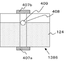
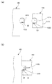
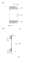
次に、リザーバタンク1386の構成について説明する。図3(a)および図3(b)は、それぞれ、レベルセンサ402の配置を説明する平面図および斜視図である。また、図4は、レベルセンサ402の構成を模式的に示す断面図である。
Next, the configuration of the
図1を用いて前述したように、リザーバタンク1386の燃料収容室の内部には、3つのレベルセンサ402が設けられている。レベルセンサ402は、リザーバタンク1386の内壁に接着剤等を用いて接着することにより固定することができる。また、図3(a)中に点線で示したように、3つのレベルセンサ402は、3つすべてが一直線上に並ばないように配置されていれば特に制限はない。たとえば、レベルセンサ402を同一平面に並べて設置することができる。たとえば図22に示したように、直方体のリザーバタンク1386の3辺に沿って設けることもできる。
As described above with reference to FIG. 1, the three
また、図4に示したように、レベルセンサ402は、たとえば磁気センサとすることができる。磁気センサは、円筒形のフロートガイド408および磁石を内蔵したマグネットフロート409を有する。フロートガイド408の上下には、二つのホールセンサ407aおよびホールセンサ407bがそれぞれ設けられている。ホールセンサ407aおよびホールセンサ407bは、マグネットフロート409からの距離に応じた磁場の強さの変化を電圧変化として検知する。ホールセンサ407aおよびホールセンサ407bとして、具体的には、たとえば、旭化成電子社製ホール素子HGシリーズ等を利用することができる。
Further, as shown in FIG. 4, the
リザーバタンク1386中の燃料124の液面の変動に伴い、マグネットフロート409に内蔵された磁石がフロートガイド408の内部を上下移動する。なお、フロートガイド408内に燃料124は自由に流入可能に構成されている。磁石が上下方向に動くことにより、ホールセンサ407aおよびホールセンサ407bで検知される電圧の大きさが変化する。
As the liquid level of the
図5(a)および図5(b)は、マグネットフロート409が図4に示した位置にある場合のホールセンサ407aおよびホールセンサ407bのそれぞれにおいて検知される電圧の大きさを模式的に示す図である。図4では、リザーバタンク1386中の燃料124の液量が比較的多い場合が例示されている。マグネットフロート409がホールセンサ407aに近い側に位置している。このため、図5(a)および図5(b)を比較するとわかるように、ホールセンサ407aで検知される電圧の大きさは、ホールセンサ407bで検知される電圧の大きさよりも大きい。これらの電圧は、マグネットフロート409の位置により変動する。よって、ホールセンサ407aおよびホールセンサ407bで検知される電圧の大きさから、リザーバタンク1386中の燃料124の液面の位置を検知することができる。
FIGS. 5A and 5B schematically show the magnitudes of voltages detected in the
このとき、ホールセンサ407aおよびホールセンサ407bは、図17に示した液量演算部417に接続し、液量演算部417が、液面の解析用の記憶部428に接続する構成としてもよい。記憶部428には、たとえばホールセンサ407aおよびホールセンサ407bで検知される電圧の大きさを液面の高さに対応させるデータが記憶されている。このようにすれば、ホールセンサ407aおよびホールセンサ407bで検知された電圧の値を用いて、液量演算部417において確実に液面の位置を算出することができる。
At this time, the
また、記憶部428には、3つのレベルセンサ402で検知される液面の位置をリザーバタンク1386中の燃料124の液量に対応させるデータが記憶されている。このため、ホールセンサ407aおよびホールセンサ407bからなるレベルセンサ402を3個を用いて、リザーバタンク1386中の燃料124の残量を確実に把握することができる。
Further, the
なお、図4に示したホールセンサ407aおよびホールセンサ407に代えて、フロートガイド408に沿って複数のリードスイッチを設け、それぞれの高さにおける磁場の強さを検知することにより、液面を検出してもよい。この場合、フロートガイド408の上下移動に伴うリードスイッチの開閉を検出する検出部は、リザーバタンク1386を含む燃料電池本体100の所定の位置に設けることができる。
In place of the
次に、図1に示した燃料電池400の効果を説明する。
燃料電池400においては、リザーバタンク1386に複数のレベルセンサ402が配置されている。このため、リザーバタンク1386の液面を複数箇所について検知することができる。よって、レベルセンサ402を一つ設けた場合に比べ、リザーバタンク1386の液面を正確に検出することができる。したがって、リザーバタンク1386が傾斜した状態で使用されたり、リザーバタンク1386の液面が変動しやすい状態で使用される場合にも、リザーバタンク1386内の液体燃料の液面を確実に検出することができる。さらに、液面の位置を正確に検知可能であるため、液面の位置とリザーバタンク1386の形状に関する情報を用いて、リザーバタンク1386内の液体燃料の残量を確実に把握することができる。
Next, the effect of the
In the
複数のレベルセンサ402を設けることによりもたらされる効果は、リザーバタンク1386に3つ以上のレベルセンサ402を配設した際に顕著に発揮される。これらのレベルセンサ402のすべてが同一直線上に配置されてはいないため、リザーバタンク1386中の燃料124の液面の位置に対応する電気的信号を3点について検知することができる。また、レベルセンサ402が液量演算部417に接続している。液量演算部417において、レベルセンサ402にて得られた電気的信号と、記憶部428に記憶された情報とを用いて、レベルセンサ402の位置情報とその位置における液面情報とがセットで求められる。このため、リザーバタンク1386中の液体燃料の液面が確実に求められる。また、リザーバタンク1386内の液体燃料の残量を算出することができる。
The effect brought about by providing the plurality of
また、液量演算部417で算出された残量は、液量演算部417に接続する表示部418に表示される。よって、燃料124の残量が少なくなった際には、所定のタイミングで燃料カートリッジ401の交換または燃料124の補充を促すことが可能となる。
Further, the remaining amount calculated by the liquid
このように、リザーバタンク1386内の3点の液面を把握することにより、図3(b)に示したように、燃料電池400が傾斜している場合にも、液量演算部417において、その液面の位置を確実に把握することができる。このため、携帯型の電気機器のように、傾斜面に設置されたり、傾斜した状態で使用されたりする可能性が高い電気機器にも好適に適用可能な構成とすることができる。
Thus, by grasping the three liquid levels in the
さらに、燃料電池本体100に制御部430が設けられている場合、液量演算部417で算出されるリザーバタンク1386中の燃料124の残量に応じて、燃料カートリッジ401からの液体燃料の補給を制御することができる。このため、所望の濃度の124を安定的に供給することができる。よって、クロスオーバーを抑制しつつ、高い出力を安定的に発揮させることができる。また、制御部430を設けることにより、リザーバタンク1386中の燃料124の残量に応じて、単セル構造101の燃料極102への燃料124の供給を制御することができる。このため、燃料電池400全体を小型化しつつ、燃料124を効率よく利用し、単セル構造101における発電を長期間安定的に行わせることができる。
Further, when the
なお、本実施形態においては、レベルセンサ402をリザーバタンク1386中に配置したが、レベルセンサ402は燃料供給系を構成する他の燃料容器に設けることもできる。たとえば、燃料極102に隣接して設けられた燃料容器811または燃料カートリッジ401がレベルセンサ402を備える構成としてもよい。燃料カートリッジ401にレベルセンサ402を設ける構成については、第二の実施形態において詳細に説明する。
In the present embodiment, the
また、本実施形態において、リザーバタンク1386に2つのレベルセンサ402を設置する場合には、リザーバタンク1386の長手方向に二つのレベルセンサ402を並べて配置することができる。図6は、二つのレベルセンサ402を用いる場合について、レベルセンサ402のリザーバタンク1386への配置例を示す図である。こうすることにより、レベルセンサ402を2つとする場合にも燃料電池400またはリザーバタンク1386の傾斜を考慮して、リザーバタンク1386中の燃料124の量を把握することができる。また、少なくとも同一直線上に存在しない3つのレベルセンサ402を含む3つ以上のレベルセンサ402を設置することにより、リザーバタンク1386の液面の位置をさらに確実に検知することができる。
In the present embodiment, when two
また、本実施形態において、液量演算部417は、センサ群416で検知された液面に関する情報を用いて燃料124の残量を算出するが、このとき、複数のレベルセンサ402で指示された液面のうち、所定のものを取捨選択して用いることもできる。こうすれば、燃料124の残量をより一層正確に算出することができる。
Further, in the present embodiment, the liquid
たとえば、レベルセンサ402a〜402cのうち、あるセンサで測定された液面が測定可能な範囲を超えている場合、具体的には、たとえば、記憶部428にレベルセンサ402で検知される液面の位置の範囲を記憶させておき、リザーバタンク1386の高さを超えている場合には、このセンサの測定結果を用いないようにすることができる。また、3つのレベルセンサ402のうち、ある一つのセンサから求められた液面の位置が他の二つのセンサから求められた液面の位置から突出している場合には、突出した液面を考慮せずに、残りの二つのセンサから求められた液面の位置を用いてリザーバタンク1386内の燃料124の液面を算出してもよい。
For example, when the liquid level measured by a certain sensor among the
また、以上においては、燃料電池本体100が、図17または図18に示した燃料容器424の構成に対応するリザーバタンク1386を有する場合を例に説明したが、液量演算部417、表示部418、および記憶部428は、燃料電池本体100の所定の位置に設けられていればよく、必ずしもリザーバタンク1386に設けられていなくてもよい。
In the above description, the case where the fuel cell
たとえば、本実施形態に係る燃料電池の構成を図24のようにしてもよい。図24は、図23に示した燃料電池において、液量演算部417、表示部418、および記憶部428がリザーバタンク1386以外に設けられている構成を示す図である。
For example, the configuration of the fuel cell according to the present embodiment may be as shown in FIG. FIG. 24 is a diagram showing a configuration in which the liquid
(第二の実施形態)
第一の実施形態においては、リザーバタンク1386に3つのレベルセンサ402が設けられた構成の燃料電池400(図1)について説明したが、燃料電池において、3つのレベルセンサ402を燃料カートリッジ401に設ける構成とすることもできる。本実施形態では、こうした構成の燃料電池について説明する。
(Second embodiment)
In the first embodiment, the fuel cell 400 (FIG. 1) having the configuration in which the
図9は、本実施形態に係る燃料電池410の構成を模式的に示す平面図である。以下、第一の実施形態に記載の燃料電池400と異なる部分を中心に説明する。図9の燃料電池410においては、図1の燃料電池400においてリザーバタンク1386に設けられていた3つのレベルセンサ402が、燃料カートリッジ401の内部に配置されている。3つのレベルセンサ402の配置は、すべてが同一直線上に位置しなければよく、たとえば第一の実施形態において図22を用いて例示した配置とすることができる。
FIG. 9 is a plan view schematically showing the configuration of the
ここで、燃料カートリッジ401と燃料電池本体100の燃料流出管1111は、接続部411にて接続される。これにより、燃料カートリッジ401に収容された液体燃料が燃料電池本体100の燃料流出管1111から燃料極102へと供給される。また、レベルセンサ402に検知される電気的信号を燃料電池本体100の側で検出することが可能となる。
Here, the
図10(a)および図10(b)は、接続部411の構成を拡大して示す図である。図10(a)は、燃料カートリッジ401が燃料電池本体100に接続されていない状態を示し、図10(b)は、これらが連結された状態を示す。
FIG. 10A and FIG. 10B are views showing the
図10(a)および図10(b)に示したように、燃料カートリッジ401は、燃料流出管1111に挿入される凸状の接続部1225を有する。接続部1225の端面は、シール部材1375により被覆され、封止されている。また、接続部1225の内部の側面に導電性の端子X1(不図示)、X2、およびX3(不図示)が設けられている。これらの端子は、図12を用いて後述するように、それぞれ別のレベルセンサ402に接続している。
As shown in FIGS. 10A and 10B, the
シール部材1375は、セルフシール性を有する弾性部材である。シール部材1375として、たとえばセプタムやリシールを用いることができる。シール部材1375は、液体燃料に対する耐性を有し、密閉可能な材料とすることが好ましい。このような材料として、たとえば、エチレンプロピレンゴム、シリコーンゴム等のエラストマーを用いることができる。シール部材1375をエチレンプロピレンゴムとする場合、エチレンとプロピレンの共重合体(EPM)またはエチレンとプロピレンと第3成分の共重合体(EPDM)を用いることができる。また、シール部材1375を加硫ゴムとすることもできる。
The
また、燃料電池本体100の燃料流出管1111の端部には、接続部1225の形状に対応して凹状に成形された嵌合部1205が設けられている。嵌合部1205の後退面に、接続部411の中心軸に実質的に平行に燃料流出管1111の中心から燃料流出管1111の内外に向かって延在する中空針1379が設けられている。また、嵌合部1205の外側壁には、端子X1(不図示)、X2、およびX3(不図示)に対応する位置に導電性の端子Y1(不図示)、Y2、およびY3(不図示)が設けられている。
Further, an end portion of the
図11(a)および図11(b)は、接続部1225および嵌合部1205における端子の配置を模式的に示す平面図である。図11(a)は、燃料電池本体100の燃料流出管1111に形成された嵌合部1205に設けられた端子Y1〜Y3を示している。また、図11(b)は、燃料カートリッジ401の接続部1225に設けられた端子X1〜X3を示している。
FIG. 11A and FIG. 11B are plan views schematically showing the arrangement of terminals in the
図10(b)に示したように、嵌合部1205に接続部1225が挿入されてこれらが嵌合すると、中空針1379がシール部材1375を貫通するため、燃料カートリッジ401中の液体燃料が燃料流出管1111へと移動可能となる。また、嵌合部1205と接続部1225が嵌合すると、端子X1と端子Y1、端子X2とY2、および端子X3とY3が接触し、これらの電気的な導通が確保される。
As shown in FIG. 10B, when the connecting
燃料カートリッジ401および燃料電池本体100を以上のように構成したとき、燃料カートリッジ401内の各レベルセンサ402で検知された液面の位置は、たとえば図12に示した方法により燃料電池本体100の側で検出することができる。
When the
図12は、図9に示した燃料電池410の構成を説明する図である。図12において、燃料カートリッジ401は、端子X2、および端子X3は、それぞれレベルセンサ402a、レベルセンサ402b、およびレベルセンサ402cに接続している。
FIG. 12 is a diagram illustrating the configuration of the
また、燃料電池本体100は、複数の接続端子Y1、Y2、およびY3と、接続端子Y1〜Y3間の電気的接続状態を検出する検出部429と、検出部429に接続する液量演算部417を含む。さらに、燃料電池本体100は、液量演算部417に接続する記憶部428および表示部418を有する。
The fuel cell
測定の際には、レベルセンサ402a〜レベルセンサ402cで検知された電気的信号を、それぞれ検出部429において検出する。そして、液量演算部417は、検出部429が検出した電気的接続状態に基づき、記憶部428を参照してレベルセンサ402a〜レベルセンサ402cの液面の位置を検出する。さらに、液量演算部417は、これらの3つのレベルセンサ402を用いて検出された液面の位置に基づき、記憶部428を参照して、燃料カートリッジ401中の液体燃料の残量を算出する。そして、残量を表示部418に表示する。
At the time of measurement, the electric signals detected by the
このように、本実施形態では、燃料カートリッジ401に収容された液体燃料の残量を確実に把握することができる。このとき、レベルセンサ402で検知される電気的信号を、燃料電池本体100の側で検出することができるので、燃料カートリッジ401の構成を簡素化することが可能である。
Thus, in the present embodiment, the remaining amount of liquid fuel stored in the
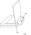
図21は、以上で説明した燃料電池を搭載した電気機器の一例を示す模式図である。本実施の形態における電気機器は、携帯型パーソナルコンピュータである。携帯型パーソナルコンピュータ210において、底面部に燃料電池本体100が設けられており、背面部に燃料カートリッジ401が装着された構成となっている。図21には示していないが、燃料カートリッジ401に3つのレベルセンサ402が設けられている。このように、本実施形態に係る燃料電池が携帯型のパーソナルコンピュータに取り付けられ、持ち運び時やコンピュータ使用時に傾けられたりしても、燃料カートリッジ401中の液体燃料の残量を確実に検知することができる。
FIG. 21 is a schematic diagram showing an example of an electric device equipped with the fuel cell described above. The electric device in this embodiment is a portable personal computer. In the portable
なお、以上においては、燃料カートリッジ401に設けられたレベルセンサ402で検知される電気的信号を、燃料電池本体100側で検出する構成としたが、燃料カートリッジ401の側でレベルセンサ402で検知される電気的信号を直接検出する構成としてもよい。
In the above description, the electric signal detected by the
たとえば、図12に示した燃料電池において、燃料カートリッジ401が検出部429、液量演算部417、記憶部428、および表示部418を備える構成とすることができる。こうすることにより、燃料カートリッジ401中の液体燃料の残量を燃料カートリッジ401自体で直接検出し、また表示することができる。
For example, in the fuel cell shown in FIG. 12, the
また、たとえば、燃料電池本体100が制御部430を有し、制御部430は、燃料カートリッジ401に設けられた液量演算部417で算出された液体燃料の残量を算出し、算出した残量に応じて燃料電池本体100の運転を制御する構成としてもよい。たとえば、図24に示した燃料電池の場合と同様に、燃料電池本体100が制御部430を有し、制御部430は、液量演算部417で算出された液体燃料の残量に応じて燃料電池本体100の運転を制御する構成としてもよい。たとえば、制御部430は、装着された燃料カートリッジ401内に残存する液体燃料の残量に応じて、図1に示したポンプ1117の駆動を制御することができる。このとき、制御部430は、燃料カートリッジ401中の燃料の残量に応じて、たとえば、燃料カートリッジ401からリザーバタンク1386への液体燃料の供給量を制御することもできる。また、制御部430が燃料カートリッジ401に設けられていてもよい。
Further, for example, the fuel cell
(第三の実施形態)
第一または第二の実施形態に係る燃料電池では、リザーバタンク1386に3つのレベルセンサ402を設けたが、レベルセンサ402と傾斜センサとを組み合わせてリザーバタンク1386または燃料カートリッジ401中の燃料124の液面を検出することもできる。以下、図1に示した燃料電池400において、3つのレベルセンサ402に代えてレベルセンサ402と傾斜センサを用い、リザーバタンク1386中の燃料124の残量を算出する場合を例に説明する。
(Third embodiment)
In the fuel cell according to the first or second embodiment, the three
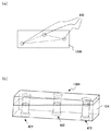
図7(a)および図7(b)は、リザーバタンク1386中の燃料124の液量を算出可能な構成を示す図である。図7(a)は斜視図であり、図7(b)は平面図である。図7(a)および図7(b)では、リザーバタンク1386に2つのレベルセンサ402を設けるとともに、燃料電池本体100に傾斜センサを1つ設けた構成を示す図である。
FIGS. 7A and 7B are diagrams showing a configuration that can calculate the amount of the
図7(a)および図7(b)に示した構成では、リザーバタンク1386の長手方向に二つのレベルセンサ402を並べて配置するとともに、当該長手方向の傾斜角度を検知する傾斜センサ403を配置している。傾斜センサ403は、燃料電池本体100内のリザーバタンク1386の設置面の水平面に対する傾斜角度を検知する。
In the configuration shown in FIGS. 7A and 7B, two
傾斜センサとして、設置面の傾斜角度に応じて電圧等の電気的信号が変化するように構成されたセンサを用いることができる。具体的には、たとえば、オムロン社製のD5R(リニア)等を用いることができる。このような傾斜センサを燃料電池本体100に設けることにより、レベルセンサ402の設置数が少ない場合にも、リザーバタンク1386中の燃料124の残量を確実に把握することができる。
As the tilt sensor, a sensor configured to change an electrical signal such as a voltage according to the tilt angle of the installation surface can be used. Specifically, for example, D5R (linear) manufactured by OMRON Corporation can be used. By providing such a tilt sensor in the fuel cell
図8(a)および図8(b)は、リザーバタンク1386中の燃料124の液量を算出可能な別の構成を示す図である。図8(a)は斜視図であり、図8(b)は平面図である。図7(a)および図8(b)では、リザーバタンク1386の中央付近に1つのレベルセンサ402を設けるとともに、燃料電池本体100に傾斜センサを2つ設けた構成を示す図である。
FIGS. 8A and 8B are diagrams showing another configuration that can calculate the amount of the
2つの傾斜センサ403は、リザーバタンク1386と同一平面に設置し、互いに異なる方向の傾斜角度を検知できるように配置する。こうすることにより、リザーバタンク1386に1つのレベルセンサ402のみを設置した場合であっても、2方向の傾斜角度を検出することができるため、燃料124の残量を確実に把握することができる。
The two
なお、以上においては、リザーバタンク1386の外部に傾斜センサ403を設ける構成を例に説明したが、傾斜センサ403をリザーバタンク1386の内部に設置してもよい。
In the above description, the
また、以上においては、傾斜角度に応じて電気的信号が連続的に変化する傾斜センサ403を用いる場合を例に説明したが、傾斜センサ403として、所定の角度の前後で電源が出入するスイッチタイプのセンサを用いてもよい。また、こうした傾斜センサ403には、必要に応じて適宜オフセットを設けることもできる。オフセットとして、具体的には、燃料電池400の設置面から所定の角度をなして傾斜センサを配置する角度調整台等を用いることができる。こうすれば、スイッチタイプのセンサの可動範囲を燃料電池400の使用状態に応じて調節することができる。
In the above description, the case of using the
(第四の実施形態)
以上の実施形態に記載の燃料電池において、燃料容器内の燃料成分濃度を検知する濃度センサがさらに設けられた構成とすることもできる。ここで、濃度センサを設ける燃料容器は、燃料カートリッジ401、リザーバタンク1386、燃料容器811のいずれでもよく、また、燃料供給系の他の領域に設けることもできる。
(Fourth embodiment)
In the fuel cell described in the above embodiment, a concentration sensor for detecting the fuel component concentration in the fuel container may be further provided. Here, the fuel container in which the concentration sensor is provided may be any one of the
以下、リザーバタンク1386の液量が算出される第一の実施形態に記載の燃料電池の構成を例に説明する。図19は、本実施形態に係る燃料電池の燃料容器の構成を示すブロック図である。図19に示した燃料容器は、図18に示した燃料容器424に設けられた構成要素に加え、さらに濃度センサ419、濃度演算部420、制御部430、および調節部423を有する。また、液量演算部417および濃度演算部420は、演算処理部421に含まれる。
Hereinafter, the configuration of the fuel cell described in the first embodiment in which the liquid amount in the
図19の構成では、濃度センサ419で検知される電気的信号に基づき、濃度演算部420において、リザーバタンク1386中の液体の燃料成分の濃度を算出する。そして、濃度演算部420で算出された燃料成分濃度と液量演算部417で算出された液体燃料の残量から、燃料成分残量演算部426において、リザーバタンク1386中の燃料成分の残量が算出される。
In the configuration of FIG. 19, the
このような構成とすることにより、燃料容器424の設置状態によらず、リザーバタンク1386中の燃料成分の残量を確実に把握することができる。そして、燃料成分の残量に関する情報を表示部418にて表示することができる。
With such a configuration, it is possible to reliably grasp the remaining amount of the fuel component in the
また、図20は、本実施形態に係る燃料容器の別の構成を示す図である。図20に示した燃料容器は、図19に示した構成において、演算処理部421がさらに使用可能時間演算部422を有する。こうすることにより、燃料成分残量演算部426で算出された燃料成分の残量に基づき、使用可能時間演算部422が記憶部428を参照して燃料電池400の使用可能時間を求め、表示部418に表示することができる。
FIG. 20 is a diagram showing another configuration of the fuel container according to the present embodiment. In the fuel container shown in FIG. 20, in the configuration shown in FIG. 19, the
図13は、図19または図20に示した構成が適用された燃料電池の構成を模式的に示す平面図である。図13の燃料電池の構成は基本的には図1に示した燃料電池400と同様であるが、リザーバタンク1386にさらに濃度計1119が設けられている点が異なる。
FIG. 13 is a plan view schematically showing the configuration of a fuel cell to which the configuration shown in FIG. 19 or FIG. 20 is applied. The configuration of the fuel cell in FIG. 13 is basically the same as that of the
まず、濃度計1119の構成と、リザーバタンク1386で混合されて燃料容器811に供給される燃料124の濃度制御の方法について説明する。ここでは、リザーバタンク1386に設けられた濃度計1119を用いてリザーバタンク1386中の液体のメタノール濃度を検出し、各ポンプ1117の動作をフィードバック制御する場合を例に説明する。
First, the configuration of the
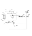
図14は、燃料電池本体1109に設けられた燃料濃度の測定を行う濃度測定系の周辺構成を示す図である。図14では、リザーバタンク1386中に設けられたレベルセンサ402等の液量検出系の構成は図示していない。
FIG. 14 is a diagram showing a peripheral configuration of a concentration measurement system that measures the fuel concentration provided in the fuel cell main body 1109. In FIG. 14, the configuration of the liquid amount detection system such as the
図14において、濃度測定系は、センサ668と、濃度演算部420と、制御部430と、ポンプ1117とを含む。センサ668および濃度演算部420が濃度計1119に対応する構成となっている。
In FIG. 14, the concentration measurement system includes a
センサ668は、リザーバタンク1386内の燃料124の燃料成分濃度を検出するのに用いられる。センサ668は、高分子膜665と、第1の電極端子666と、第2の電極端子667とを含む。高分子膜665は、プロトン伝導性を有する高分子膜である。高分子膜665は、リザーバタンク1386中の燃料124を含浸するように構成され、燃料124中のアルコール濃度に応じてプロトン伝導度が変化する材料により構成される。この構成によれば、高分子膜665のプロトン伝導度の変化に基づき、リザーバタンク1386中の燃料124のメタノール濃度を検出することができる。
高分子膜665は、燃料124のアルコール濃度に応じてプロトン伝導度が変化する材料により構成することができる。たとえば、単セル構造101の固体電解質膜114と同様の材料により構成することができる。
The
第1の電極端子666および第2の電極端子667は、高分子膜665表面または高分子膜665中に互いに離間して設けられる。ここで、高分子膜665は、アルコール濃度に応じてプロトン伝導度が変化する材料により構成されるので、第1の電極端子666と第2の電極端子667との間に高分子膜665を介して電流を流した場合、リザーバタンク1386中の燃料124のアルコール濃度に応じて第1の電極端子666および第2の電極端子667間の抵抗値が変化する。濃度演算部420は、第1の電極端子666および第2の電極端子667間の抵抗値に基づき、リザーバタンク1386中の燃料124のアルコール濃度を測定する。濃度演算部420の詳細な構成については後述する。濃度演算部420が測定したリザーバタンク1386中の燃料124のアルコール濃度は制御部430に伝達される。
The
図15(a)および図15(b)は、センサ668を詳細に示す図である。図15(a)は、センサ668の第1の電極端子666および第2の電極端子667が設けられた面を示す図、図15(b)は、図15(a)の側面図である。第1の電極端子666および第2の電極端子667は、燃料124中に安定に存在し、導電性を有する材料により構成することができる。第1の電極端子666および第2の電極端子667は、導電性ペーストにより高分子膜665に貼り付けることができる。導電性ペーストとしては、金や銀等の金属を含むポリマーペーストや、アクリルアミド等ポリマー自体が導電性を有するポリマーペーストを用いることができる。第1の電極端子666および第2の電極端子667は、それぞれ配線710aおよび配線710bを介して、図14に示した濃度演算部420に電気的に接続される。
FIG. 15A and FIG. 15B are diagrams showing the
なお、以上で説明したのは、センサ668の構成の一例であって、濃度の測定方法は以下の態様に限られない。たとえば、電極間の抵抗値の変化を測定することにより濃度を算出するセンサであってもよい。また、電極間に流す電流は、直流とすることもできる。
Note that what has been described above is an example of the configuration of the
図14および図15に示した構成の濃度測定系を設けることにより、図19または図20に示した濃度演算部420において、リザーバタンク1386中の燃料124の燃料成分濃度が確実に算出され、燃料成分残量演算部426に伝達される。また、液量測定部412においては、レベルセンサ402にて得られた液面レベルからリザーバタンク1386中の液量が算出される。この液量も、燃料成分残量演算部426に伝達される。
By providing the concentration measurement system having the configuration shown in FIGS. 14 and 15, the
なお、制御部430は、燃料成分残量演算部426で算出された燃料成分の残量に基づき、調節部423の駆動を制御することができる。具体的には、たとえば、図13に示した燃料電池に設けられたポンプ1117の運転を制御することができる。
The
なお、図14に示したように、燃料カートリッジ401は、燃料極102に供給される燃料124よりも燃料成分の濃度が高い高濃度燃料725を収容していてもよい。そして、制御部430は、濃度演算部420により測定されたアルコール濃度が適正な範囲内であるか否かを判断し、リザーバタンク1386中の燃料124のアルコール濃度が適正な範囲内となるようにポンプ1117を制御することができる。このポンプ1117は、制御部430の制御に基づき、燃料カートリッジ401からリザーバタンク1386に供給する高濃度燃料725の供給量を制御する。
As shown in FIG. 14, the
また、制御部430は、ポンプ1117を制御する処理を繰り返してもリザーバタンク1386中の燃料124のアルコール濃度が適正な範囲内にならない場合、表示部418に警告を発生させてもよい。さらに、制御部430は、リザーバタンク1386から燃料容器811への燃料124の供給を制御してもよい。このとき、制御部430は、燃料流出管1111中のポンプ1117の動作を制御する。この制御は、燃料電池本体100からの出力をさらに検出し、検出値に応じてフィードバックする構成とすることもできる。
In addition, the
図16は、濃度演算部420の構成を詳細に示す図である。濃度演算部420は、第1の電極端子666と第2の電極端子667との間の抵抗値を測定する抵抗測定部(R/O)682と、抵抗測定部682が測定した抵抗値に基づき、リザーバタンク1386中のアルコール濃度を算出する濃度算出部(S/O)684と、第1の電極端子666と第2の電極端子667の間の抵抗値とメタノール濃度との関係を示す参照データを記憶する参照データ記憶部685とを含む。抵抗測定部682としては、たとえばブリッジを備えた交流インピーダンスメータを用いることができる。第1の電極端子666と第2の電極端子667との間の抵抗値は、20mV以下の低振幅の交流を用いて測定することができる。濃度算出部684は、参照データ記憶部685を参照して参照データに基づき濃度算出部684が測定した抵抗値からメタノール濃度を算出する。
FIG. 16 is a diagram showing the configuration of the
この構成によれば、高分子膜665に第1の電極端子666および第2の電極端子667を付けただけの簡易な構成でリザーバタンク1386中のアルコール濃度を検出し、燃料容器811に供給する燃料124の濃度を制御することができる。
According to this configuration, the alcohol concentration in the
そして、レベルセンサ402で検知される燃料124の残量と燃料124中の燃料成分の濃度とを組み合わせることにより、リザーバタンク1386中の燃料成分の残量をさらに正確に把握することができる。燃料成分の残量を把握することにより、単セル構造101に供給する燃料124の濃度の制御をより一層確実に行うことができる。
By combining the remaining amount of the
また、記憶部428に燃料成分の残量の基準値を記憶させておき、残量が記憶部428に記憶された所定の基準を下回った場合には、表示部418に警告表示を行ってもよい。こうすれば、燃料成分の残量が所定の基準を下回った際に、燃料カートリッジ401の交換をうながす構成とすることが可能となる。
Further, the reference value of the remaining amount of the fuel component is stored in the
なお、以上の実施形態に記載の燃料電池において、燃料容器に設けられる液面センサはレベルセンサ402には限定されず、他のセンサとしてもよい。たとえば、燃料容器に透明な窓部を設けておき、窓部から燃料容器に光を照射してその反射率または透過率を測定することにより液面を求める構成の光センサを用いることもできる。
In the fuel cell described in the above embodiment, the liquid level sensor provided in the fuel container is not limited to the
また、燃料カートリッジ1103のタンク中の液体の液面の検出方法は以上の方法に限られない。たとえば、静電容量を用いたセンサや、超音波センサなどを用いることもできる。 Further, the method for detecting the liquid level in the tank of the fuel cartridge 1103 is not limited to the above method. For example, a sensor using capacitance, an ultrasonic sensor, or the like can be used.
また、以上の実施形態に記載の燃料電池において、濃度の異なる複数の液体燃料を保持し、燃料電池本体に着脱可能な燃料カートリッジを有する構成としてもよい。この場合、濃度の異なる複数の液体燃料を混合し、所定の濃度に調製した後、燃料極に供給するリザーバタンク1386は、燃料カートリッジ中の複数のタンクのうち一つとすることもできるし、燃料電池本体100に設けることもできる。
Further, the fuel cell described in the above embodiment may be configured to have a fuel cartridge that holds a plurality of liquid fuels having different concentrations and is detachable from the fuel cell main body. In this case, after a plurality of liquid fuels having different concentrations are mixed and adjusted to a predetermined concentration, the
これらの構成においても、燃料カートリッジを構成する複数のタンクのうちの一つまたは複数にセンサ群416を設けることにより、液量演算部417で当該タンク中の液量を算出することができる。このため、タンクが空になった際には速やかに交換することができる。さらに、複数のタンクを分離可能な構成としてもよい。こうすれば、それぞれのタンクを異なるタイミングで交換することができる。
Also in these configurations, by providing the
100 燃料電池本体
101 単セル構造
102 燃料極
108 酸化剤極
114 固体電解質膜
124 燃料
210 携帯型パーソナルコンピュータ
400 燃料電池
401 燃料カートリッジ
402 レベルセンサ
402a レベルセンサ
402b レベルセンサ
402c レベルセンサ
403 傾斜センサ
407 ホールセンサ
407a ホールセンサ
407b ホールセンサ
408 フロートガイド
409 マグネットフロート
410 燃料電池
411 接続部
412 液量測定部
416 センサ群
417 液量演算部
418 表示部
419 濃度センサ
420 濃度演算部
421 演算処理部
422 使用可能時間演算部
423 調節部
424 燃料容器
426 燃料成分残量演算部
427a 液面
427b 液面
427c 液面
427d 液面
428 記憶部
429 検出部
430 制御部
665 高分子膜
666 電極端子
667 電極端子
668 センサ
682 抵抗測定部
684 濃度算出部
685 参照データ記憶部
710a 配線
710b 配線
725 高濃度燃料
811 燃料容器
853 仕切板
1103 燃料カートリッジ
1105 高濃度燃料タンク
1109 燃料電池本体
1111 燃料流出管
1113 燃料回収管
1115 高濃度燃料流入管
1117 ポンプ
1119 濃度計
1123 コネクタ
1205 嵌合部
1225 接続部
1361 燃料カートリッジ
1375 シール部材
1379 中空針
1386 リザーバタンク
DESCRIPTION OF
Claims (15)
前記燃料収容室内の複数箇所における前記液体燃料の液面の位置を検知する液面検知部と、
前記液面検知部で検知された前記液面の位置から前記液体燃料の残量を算出する演算部と、
を有することを特徴とする燃料電池用燃料容器。 A fuel storage chamber for storing liquid fuel to be supplied to a fuel electrode of a fuel cell applied to a portable electrical device;
A liquid level detector for detecting the position of the liquid level of the liquid fuel at a plurality of locations in the fuel storage chamber;
A calculation unit that calculates the remaining amount of the liquid fuel from the position of the liquid level detected by the liquid level detection unit;
A fuel container for a fuel cell, comprising:
前記液面検知部は、前記燃料収容室に設けられ、前記液面の位置を検知する3個以上の液面センサを含み、
前記液面センサは、すべてが同一直線上に位置しないように設けられていることを特徴とする燃料電池用燃料容器。 The fuel container for a fuel cell according to claim 1,
The liquid level detection unit includes three or more liquid level sensors that are provided in the fuel storage chamber and detect the position of the liquid level.
A fuel container for a fuel cell, wherein all of the liquid level sensors are provided so as not to be positioned on the same straight line.
前記液面検知部は、前記燃料収容室に設けられ、前記液面の位置を検知する2個以上の液面センサと、
前記液面の傾斜状態を検知する傾斜センサと、
を含むことを特徴とする燃料電池用燃料容器。 The fuel container for a fuel cell according to claim 1,
The liquid level detection unit is provided in the fuel storage chamber, and two or more liquid level sensors for detecting the position of the liquid level;
An inclination sensor for detecting an inclination state of the liquid surface;
A fuel container for a fuel cell, comprising:
前記液面検知部は、前記燃料収容室に設けられ、前記液面の位置を検知する液面センサと、
前記液面の傾斜状態を検知する複数の傾斜センサと、を含むことを特徴とする燃料電池用燃料容器。 The fuel container for a fuel cell according to claim 1,
The liquid level detection unit is provided in the fuel storage chamber, and a liquid level sensor that detects the position of the liquid level;
A fuel container for a fuel cell, comprising: a plurality of inclination sensors for detecting an inclination state of the liquid surface.
前記液面検知部は、
磁性体を備え、前記液面に沿って移動するフロートと、
前記フロートの位置を検知する磁気センサと、
を有することを特徴とする燃料電池用燃料容器。 The fuel container for a fuel cell according to any one of claims 1 to 4,
The liquid level detector is
A float that includes a magnetic body and moves along the liquid surface;
A magnetic sensor for detecting the position of the float;
A fuel container for a fuel cell, comprising:
前記燃料極に供給される液体燃料が収容される燃料収容室を備える燃料容器と、
前記燃料収容室内の複数箇所における前記液体燃料の液面の位置を検知する液面検知部と、
前記液面検知部で検知された前記液面の位置から前記液体燃料の残量を算出する演算部と、
を含むことを特徴とする携帯電気機器用燃料電池。 A fuel cell body having a fuel electrode;
A fuel container including a fuel storage chamber in which liquid fuel supplied to the fuel electrode is stored;
A liquid level detector for detecting the position of the liquid level of the liquid fuel at a plurality of locations in the fuel storage chamber;
A calculation unit that calculates the remaining amount of the liquid fuel from the position of the liquid level detected by the liquid level detection unit;
A fuel cell for portable electric equipment, comprising:
前記液体燃料が収容され、当該携帯電気機器用燃料電池に着脱可能に設けられる燃料カートリッジと、
前記燃料極または酸化剤極から排出される液体を回収する燃料回収部と、をさらに備え、
前記燃料容器は、前記燃料カートリッジと前記燃料回収部とに連通する燃料混合槽であることを特徴とする携帯電気機器用燃料電池。 The fuel cell for portable electric equipment according to claim 9 or 10,
A fuel cartridge that contains the liquid fuel and is detachably provided in the fuel cell for portable electrical equipment;
A fuel recovery part for recovering the liquid discharged from the fuel electrode or the oxidant electrode,
The fuel cell according to claim 1, wherein the fuel container is a fuel mixing tank communicating with the fuel cartridge and the fuel recovery unit.
Priority Applications (1)
| Application Number | Priority Date | Filing Date | Title |
|---|---|---|---|
| JP2004103664A JP2005293894A (en) | 2004-03-31 | 2004-03-31 | Fuel container for fuel cell, fuel cell for pocket electrical equipment using it, and pocket electrical equipment |
Applications Claiming Priority (1)
| Application Number | Priority Date | Filing Date | Title |
|---|---|---|---|
| JP2004103664A JP2005293894A (en) | 2004-03-31 | 2004-03-31 | Fuel container for fuel cell, fuel cell for pocket electrical equipment using it, and pocket electrical equipment |
Publications (1)
| Publication Number | Publication Date |
|---|---|
| JP2005293894A true JP2005293894A (en) | 2005-10-20 |
Family
ID=35326617
Family Applications (1)
| Application Number | Title | Priority Date | Filing Date |
|---|---|---|---|
| JP2004103664A Pending JP2005293894A (en) | 2004-03-31 | 2004-03-31 | Fuel container for fuel cell, fuel cell for pocket electrical equipment using it, and pocket electrical equipment |
Country Status (1)
| Country | Link |
|---|---|
| JP (1) | JP2005293894A (en) |
Cited By (6)
| Publication number | Priority date | Publication date | Assignee | Title |
|---|---|---|---|---|
| JP2007134311A (en) * | 2005-11-09 | 2007-05-31 | Syspotek Corp | Method and device of detecting fuel container liquid level of fuel cell |
| JP2007134314A (en) * | 2005-11-10 | 2007-05-31 | Samsung Sdi Co Ltd | FUEL CELL SYSTEM AND METHOD FOR DRIVING FUEL CELL PERIPHERAL DEVICE |
| JP2008137709A (en) * | 2006-12-04 | 2008-06-19 | Casio Comput Co Ltd | Container, power generator and electronic device |
| JP2008192430A (en) * | 2007-02-02 | 2008-08-21 | Ricoh Co Ltd | FUEL CELL UNIT, ELECTRONIC DEVICE, AND IMAGE FORMING APPARATUS |
| JP2010262341A (en) * | 2009-04-30 | 2010-11-18 | Nec Corp | Portable information processing apparatus and method of controlling the same |
| JP2014120434A (en) * | 2012-12-19 | 2014-06-30 | Daihatsu Motor Co Ltd | Circulating fluid volume calculation device |
Citations (4)
| Publication number | Priority date | Publication date | Assignee | Title |
|---|---|---|---|---|
| JPS6395322A (en) * | 1986-10-09 | 1988-04-26 | Kurita Water Ind Ltd | Liquid level meter |
| JPH0224330A (en) * | 1988-07-14 | 1990-01-26 | Toray Ind Inc | Production of polyamide foam |
| US20030190504A1 (en) * | 2002-04-08 | 2003-10-09 | Fisher Allison M. | System and method for controlling gas transport in a fuel cell |
| JP2004093409A (en) * | 2002-08-30 | 2004-03-25 | Casio Comput Co Ltd | Fuel cartridge, portable device using the same, and remaining amount detection method |
-
2004
- 2004-03-31 JP JP2004103664A patent/JP2005293894A/en active Pending
Patent Citations (4)
| Publication number | Priority date | Publication date | Assignee | Title |
|---|---|---|---|---|
| JPS6395322A (en) * | 1986-10-09 | 1988-04-26 | Kurita Water Ind Ltd | Liquid level meter |
| JPH0224330A (en) * | 1988-07-14 | 1990-01-26 | Toray Ind Inc | Production of polyamide foam |
| US20030190504A1 (en) * | 2002-04-08 | 2003-10-09 | Fisher Allison M. | System and method for controlling gas transport in a fuel cell |
| JP2004093409A (en) * | 2002-08-30 | 2004-03-25 | Casio Comput Co Ltd | Fuel cartridge, portable device using the same, and remaining amount detection method |
Cited By (7)
| Publication number | Priority date | Publication date | Assignee | Title |
|---|---|---|---|---|
| JP2007134311A (en) * | 2005-11-09 | 2007-05-31 | Syspotek Corp | Method and device of detecting fuel container liquid level of fuel cell |
| JP2007134314A (en) * | 2005-11-10 | 2007-05-31 | Samsung Sdi Co Ltd | FUEL CELL SYSTEM AND METHOD FOR DRIVING FUEL CELL PERIPHERAL DEVICE |
| US8142945B2 (en) | 2005-11-10 | 2012-03-27 | Samsung Sdi Co., Ltd. | Method for controlling peripheral system and fuel cell system using the same |
| JP2008137709A (en) * | 2006-12-04 | 2008-06-19 | Casio Comput Co Ltd | Container, power generator and electronic device |
| JP2008192430A (en) * | 2007-02-02 | 2008-08-21 | Ricoh Co Ltd | FUEL CELL UNIT, ELECTRONIC DEVICE, AND IMAGE FORMING APPARATUS |
| JP2010262341A (en) * | 2009-04-30 | 2010-11-18 | Nec Corp | Portable information processing apparatus and method of controlling the same |
| JP2014120434A (en) * | 2012-12-19 | 2014-06-30 | Daihatsu Motor Co Ltd | Circulating fluid volume calculation device |
Similar Documents
| Publication | Publication Date | Title |
|---|---|---|
| JP4807077B2 (en) | Alcohol concentration measurement method, alcohol concentration measurement device, and fuel cell system including the device | |
| CN100576615C (en) | Power generation module, system, driving method of power generation module | |
| JP4795266B2 (en) | Liquid storage container and liquid level detection device used in fuel cell system | |
| US7651804B2 (en) | Fuel cartridge for fuel cell and fuel cell with the fuel cartridge | |
| JP2004093409A (en) | Fuel cartridge, portable device using the same, and remaining amount detection method | |
| JP2005293894A (en) | Fuel container for fuel cell, fuel cell for pocket electrical equipment using it, and pocket electrical equipment | |
| JP5141167B2 (en) | Electrolytic solution and electrochemical device | |
| US20110217614A1 (en) | Direct formic acid fuel cell performing real time measurement and control of concentration of formic acid and operation method thereof | |
| JP2006253079A (en) | FUEL CELL UNIT, FUEL CELL UNIT ASSEMBLY, AND ELECTRONIC DEVICE | |
| JP2006047065A (en) | Solution concentration measuring device | |
| KR100795495B1 (en) | Fuel cell | |
| JP2009295329A (en) | Liquid tank, liquid residue detection system, and liquid residue detection method | |
| KR100626088B1 (en) | Liquid Fuel Cartridge with Vise Table Structure | |
| CN101223666B (en) | The fuel cell | |
| CN100379068C (en) | Liquid fuel cartridge and liquid direct fuel cell having the liquid fuel cartridge | |
| KR20060107153A (en) | Fuel level alarm and fuel storage and fuel cell system | |
| JP2007073190A (en) | Fuel concentration sensor and fuel envelope for fuel cell using the same | |
| JP2004071183A (en) | Fuel remaining amount notifying device, fuel remaining amount notifying method, and fuel replenishing method in fuel cell | |
| JP2007059315A (en) | Battery holder, fuel cell module and electronic device | |
| JP2008159363A (en) | Portable fuel cell and control method of portable fuel cell | |
| JP2009087670A (en) | Buffer tank and fuel cell device equipped with the same | |
| JP2016110785A (en) | Fuel battery system | |
| KR20070042815A (en) | Fuel cartridge for fuel cell and fuel cell system using same | |
| KR20060135388A (en) | Fuel level detection device and fuel cell system employing the same | |
| JP2008123771A (en) | Power generation module and electronic device |
Legal Events
| Date | Code | Title | Description |
|---|---|---|---|
| A621 | Written request for application examination |
Free format text: JAPANESE INTERMEDIATE CODE: A621 Effective date: 20050822 |
|
| A977 | Report on retrieval |
Free format text: JAPANESE INTERMEDIATE CODE: A971007 Effective date: 20081001 |
|
| A131 | Notification of reasons for refusal |
Free format text: JAPANESE INTERMEDIATE CODE: A131 Effective date: 20081118 |
|
| A521 | Written amendment |
Free format text: JAPANESE INTERMEDIATE CODE: A523 Effective date: 20090119 |
|
| A131 | Notification of reasons for refusal |
Free format text: JAPANESE INTERMEDIATE CODE: A131 Effective date: 20100330 |
|
| A521 | Written amendment |
Free format text: JAPANESE INTERMEDIATE CODE: A523 Effective date: 20100519 |
|
| A02 | Decision of refusal |
Free format text: JAPANESE INTERMEDIATE CODE: A02 Effective date: 20110419 |