JP2005293884A - X-ray generator - Google Patents
X-ray generator Download PDFInfo
- Publication number
- JP2005293884A JP2005293884A JP2004103311A JP2004103311A JP2005293884A JP 2005293884 A JP2005293884 A JP 2005293884A JP 2004103311 A JP2004103311 A JP 2004103311A JP 2004103311 A JP2004103311 A JP 2004103311A JP 2005293884 A JP2005293884 A JP 2005293884A
- Authority
- JP
- Japan
- Prior art keywords
- imaging
- electron beam
- target
- electron
- electron lens
- Prior art date
- Legal status (The legal status is an assumption and is not a legal conclusion. Google has not performed a legal analysis and makes no representation as to the accuracy of the status listed.)
- Pending
Links
- 238000003384 imaging method Methods 0.000 claims abstract description 109
- 238000010894 electron beam technology Methods 0.000 claims abstract description 60
- 238000003780 insertion Methods 0.000 claims abstract description 11
- 230000037431 insertion Effects 0.000 claims abstract description 11
- 238000012790 confirmation Methods 0.000 claims description 65
- 230000005284 excitation Effects 0.000 abstract description 30
- 239000011248 coating agent Substances 0.000 abstract 1
- 238000000576 coating method Methods 0.000 abstract 1
- 238000000034 method Methods 0.000 description 8
- 239000003973 paint Substances 0.000 description 8
- 229910052790 beryllium Inorganic materials 0.000 description 7
- ATBAMAFKBVZNFJ-UHFFFAOYSA-N beryllium atom Chemical compound [Be] ATBAMAFKBVZNFJ-UHFFFAOYSA-N 0.000 description 7
- 238000010586 diagram Methods 0.000 description 3
- 238000002474 experimental method Methods 0.000 description 3
- 238000007689 inspection Methods 0.000 description 3
- 230000001133 acceleration Effects 0.000 description 2
- 230000004075 alteration Effects 0.000 description 2
- 230000015572 biosynthetic process Effects 0.000 description 2
- 239000000498 cooling water Substances 0.000 description 2
- 239000000203 mixture Substances 0.000 description 2
- RYGMFSIKBFXOCR-UHFFFAOYSA-N Copper Chemical compound [Cu] RYGMFSIKBFXOCR-UHFFFAOYSA-N 0.000 description 1
- 230000005540 biological transmission Effects 0.000 description 1
- 229910052802 copper Inorganic materials 0.000 description 1
- 239000010949 copper Substances 0.000 description 1
- 238000005520 cutting process Methods 0.000 description 1
- 239000005355 lead glass Substances 0.000 description 1
- 238000004519 manufacturing process Methods 0.000 description 1
- 239000000463 material Substances 0.000 description 1
- 230000002093 peripheral effect Effects 0.000 description 1
- 238000001454 recorded image Methods 0.000 description 1
- WFKWXMTUELFFGS-UHFFFAOYSA-N tungsten Chemical compound [W] WFKWXMTUELFFGS-UHFFFAOYSA-N 0.000 description 1
Images


Landscapes
- X-Ray Techniques (AREA)
Abstract
Description
本発明は、2段式の電子レンズを備えるX線発生装置に関する。 The present invention relates to an X-ray generator provided with a two-stage electron lens.
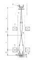
図1は2段式の電子レンズを備える従来のX線発生装置の構成図である。電子銃10で発生した電子ビーム12は,第1の電子レンズ14によって第1の結像点16に結像され,さらに,第2の電子レンズ18によってターゲット20上に結像される。第2の結像点はターゲット20の表面上に位置する。ターゲット20の焦点からはX線23が発生する。このような2段式の電子レンズを使うことで,ターゲット20上の焦点サイズを小さくすることができる。したがって,このような2段式の電子レンズは,微小焦点サイズのX線発生装置において採用される。微小焦点サイズのX線発生装置は,例えばX線顕微鏡で使われる。
FIG. 1 is a block diagram of a conventional X-ray generator having a two-stage electron lens. The
電子銃10の位置での電子ビーム12の断面サイズをSとし,電子銃10から第1の電子レンズ14の中心までの距離をa,第1の電子レンズ14の中心から第1の結像点16までの距離をf1,第1の結像点16から第2の電子レンズ18の中心までの距離をb,第2の電子レンズ18の中心からターゲット20までの距離をf2とすると,ターゲット上の焦点サイズFは,収差を無視すれば,図9の(1)式で算出される。
The cross-sectional size of the
ここで,電子銃10,第1の電子レンズ14,第2の電子レンズ18及びターゲット20の位置を固定すると仮定し,かつ,電子銃10の位置における電子ビーム12の断面サイズSも一定であると仮定すると,ターゲット20上の焦点サイズは距離f1と距離bに依存する。第1の電子レンズ14と第2の電子レンズ18の位置は固定なので,b+f1は一定である。したがって,焦点サイズは距離f1のみに依存し,この距離f1を変えることで,焦点サイズを変えることができる。距離f1を変えるには,第1の電子レンズ14の励磁電流を変えればよい。その場合,距離bが変わるので,ターゲット20上へ電子ビームを結像させるために,第2の電子レンズ18の励磁電流も変える必要がある。このように,第1の電子レンズの励磁電流を変えた場合には,第2の電子レンズの励磁電流も変える必要がある。
Here, it is assumed that the positions of the
図1に示すような2段式の電子レンズを用いた電子ビーム集束装置はよく知られており,例えば,次の特許文献1に記載されている。
この特許文献1は,電子銃から出た電子ビームを試料上に集束させる装置において,第1の電子レンズと第2の電子レンズの励磁電流をそれぞれ調整することで,試料上での電子ビームのスポットサイズを変更することができる。そして第1の電子レンズの励磁電流を変えた場合には,それに応じて,第2の電子レンズの励磁電流も変えている。
This
また,マイクロフォーカスX線管に2段式の電子レンズを設けたものとしては,次の特許文献2が知られている。
本発明の実施例の説明では,マイクロフォーカスX線発生装置の焦点サイズを測定することに言及しているが,この種の技術については,上述の特許文献2に開示されており,さらには,次の非特許文献1と非特許文献2にも開示されている。非特許文献1は非特許文献2を紹介した記事である。
図1の2段式の電子レンズを用いると,次のような問題がある。磁界型の電子レンズの場合,その結像倍率は,電子ビームの加速電圧(X線管においては管電圧に相当する)と励磁電流とに依存する。以下の説明では,加速電圧は一定であると仮定して,励磁電流の調整について説明する。ターゲット20上の電子ビームのスポットサイズ(これを焦点サイズという)を変える場合,まず,第1の電子レンズ14の励磁電流を変えてf1を所望の値に調整する。これにより,第1の電子レンズ14の結像倍率(f1/a)が変わる。結像距離f1が変わると距離bが変わるので,ターゲット20上にちょうど第2の結像点を位置させるためには,第2の電子レンズ18の励磁電流も調整する必要がある。第2の電子レンズ18の励磁電流を調整すれば,第2の電子レンズ18の結像倍率(f2/b)も変わる。ところで,このような調整作業において,現実には,第1の結像点16がどの位置にあるのかは不明である。したがって,第1の電子レンズの励磁電流と第2の電子レンズの励磁電流の組み合わせを任意に変えて,ターゲット上の焦点を観察し,その焦点がボケないような励磁電流の組み合わせを見つける必要がある。そして,そのような励磁電流の組み合わせと,得られたX線焦点のサイズとの関係を,データとして記録しておく必要がある。任意のX線焦点サイズを得ようと思えば,励磁電流の組み合わせについて膨大なデータ集積が必要になる。
When the two-stage electron lens of FIG. 1 is used, there are the following problems. In the case of a magnetic field type electron lens, the imaging magnification depends on the acceleration voltage of the electron beam (corresponding to the tube voltage in the X-ray tube) and the excitation current. In the following description, the adjustment of the excitation current will be described on the assumption that the acceleration voltage is constant. When changing the spot size of the electron beam on the target 20 (this is called the focal spot size), first, the excitation current of the
本発明は,このような問題点を解決するためになされたものであり,その目的は,2段式の電子レンズを備えていても,焦点サイズを容易に変更可能なX線発生装置を提供することにある。 The present invention has been made to solve such problems, and an object of the present invention is to provide an X-ray generator capable of easily changing the focal spot size even if it has a two-stage electron lens. There is to do.
本発明に係るX線発生装置は,次の構成を備えている。(ア)電子ビームを発生する電子ビーム発生源。(イ)前記電子ビームを第1の結像点に結像させるための第1の電子レンズ。(ウ)前記第1の結像点を通過した電子ビームを第2の結像点に結像させるための第2の電子レンズ。(エ)前記第1の結像点の位置に選択的に配置可能で,電子ビームの照射を受けて結像確認用のX線を発生する結像確認用ターゲット。(オ)前記結像確認用ターゲットから発生したX線を観察するための観察装置。(カ)前記第2の結像点の位置に配置されて,電子ビームの照射を受けて主X線を発生する主ターゲット。 The X-ray generator according to the present invention has the following configuration. (A) An electron beam source that generates an electron beam. (A) a first electron lens for imaging the electron beam at a first imaging point; (C) a second electron lens for forming an image of the electron beam that has passed through the first imaging point on the second imaging point; (D) An imaging confirmation target that can be selectively placed at the position of the first imaging point and generates X-rays for imaging confirmation upon irradiation with an electron beam. (E) An observation device for observing X-rays generated from the imaging confirmation target. (F) A main target that is arranged at the position of the second imaging point and generates main X-rays upon irradiation with an electron beam.
本発明は,結像確認用ターゲットを用いて,第1の結像点における結像状態を確認しながら,第1の電子レンズの励磁電流を調整することができる。したがって,第1の電子レンズの励磁電流を容易に最適化することができる。任意の焦点サイズを得るためには,そのような焦点サイズが得られるような位置に結像確認用ターゲットを配置して,その結像確認用ターゲットからのX線を観察装置で観察しながら,第1の電子レンズの励磁電流を調整すればよい。 According to the present invention, the excitation current of the first electron lens can be adjusted while confirming the imaging state at the first imaging point using the imaging confirmation target. Therefore, the excitation current of the first electron lens can be easily optimized. In order to obtain an arbitrary focal size, an imaging confirmation target is arranged at a position where such a focal size is obtained, and X-rays from the imaging confirmation target are observed with an observation device. The excitation current of the first electron lens may be adjusted.
結像確認用ターゲットは,結像確認のときだけX線発生装置に取り付けて,それ以外のときは取り外すようにしてもよい。あるいは,結像確認用ターゲットを常にX線発生装置に取り付けておいて,その位置を,電子ビームの経路上の挿入位置と,電子ビームの経路から外れた退避位置との間で切り換えるようにしてもよい。 The imaging confirmation target may be attached to the X-ray generator only at the time of imaging confirmation and removed at other times. Alternatively, the imaging confirmation target is always attached to the X-ray generator, and its position is switched between the insertion position on the electron beam path and the retracted position off the electron beam path. Also good.
結像確認用ターゲットは,電子ビームに沿った方向に移動可能にするのが好ましい。これにより,いろいろな結像倍率(すなわち,主ターゲット上のいろいろな焦点サイズ)について結像確認作業ができる。 The imaging confirmation target is preferably movable in the direction along the electron beam. Thereby, it is possible to perform an imaging confirmation operation for various imaging magnifications (that is, various focal sizes on the main target).
本発明は,電子レンズの励磁電流と結像距離との関係についてのデータをあらかじめ用意しておかなくても,結像確認用ターゲットを用いて,第1の電子レンズの結像状態を確認しながら第1の電子レンズの励磁電流を最適値に調整できるので,主ターゲット上の焦点サイズを自由に変えることができる。また,主ターゲットの位置を固定したままで,焦点サイズを変えることができる。 In the present invention, the imaging state of the first electronic lens can be confirmed using the imaging confirmation target without preparing data on the relationship between the excitation current of the electron lens and the imaging distance in advance. However, since the exciting current of the first electron lens can be adjusted to the optimum value, the focal spot size on the main target can be freely changed. In addition, the focus size can be changed while the position of the main target is fixed.
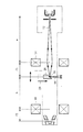
以下,図面を参照して本発明の実施例を詳しく説明する。図2は本発明の第1実施例のX線発生装置の基本構成を示す側面断面図である。このX線発生装置は2段式の電子レンズを備えていて,微小焦点サイズを得ることができる。このX線発生装置は細長い真空容器22を備えており,この真空容器22の内部空間は真空に維持されている。真空容器22の内部の長手方向の一端付近には電子銃10が配置されていて,真空容器22の他端付近には主ターゲット20が配置されている。電子銃10は陰極フィラメント24とウェーネルト円筒26を備えている。電子銃10から放出された電子ビーム12は,アノード27によって加速される。電子銃10と主ターゲット20との間には管電圧が印加される。電子ビーム12は,第1の電子レンズ14によって集束されて,第1の結像点16に結像される。さらに,第1の結像点16を通過した電子ビームは,第2の電子レンズ18によって集束されて,第2の結像点に結像される。第2の結像点の位置に主ターゲット20の表面が位置している。主ターゲット20のX線焦点からは主X線23が発生する。主ターゲット20の内部には冷却水通路21が形成されていて,主ターゲット20は冷却水により冷却される。
Hereinafter, embodiments of the present invention will be described in detail with reference to the drawings. FIG. 2 is a side sectional view showing the basic structure of the X-ray generator of the first embodiment of the present invention. This X-ray generator is equipped with a two-stage electron lens and can obtain a micro focus size. This X-ray generator is provided with an
電子銃10の位置での電子ビームの断面サイズをSとし,電子銃10から第1の電子レンズ14の中心までの距離をa,第1の電子レンズ14の中心から第1の結像点16までの距離をf1,第1の結像点16から第2の電子レンズ18の中心までの距離をb,第2の電子レンズ18の中心から主ターゲット20までの距離をf2とすると,主ターゲット20上の焦点サイズFは,収差を無視すれば,図9の(1)式で算出される。第1の電子レンズ14の結像倍率はf1/aであり,第2の電子レンズ18の結像倍率はf2/bであり,この2段式のレンズの全体の結像倍率は(f1/a)(f2/b)となる。
The cross-sectional size of the electron beam at the position of the
この実施例では,a=200mm,f1+b=200mm,f2=20mmである。すなわち,aとf2は固定であり,f1とbが可変である。電子銃10の位置での電子ビーム12の断面サイズSは60μmである。したがって,主ターゲット20上の焦点サイズFは,結像距離f1,すなわち第1の結像点16の位置,に依存する。
In this embodiment, a = 200 mm, f1 + b = 200 mm, and f2 = 20 mm. That is, a and f2 are fixed, and f1 and b are variable. The cross-sectional size S of the
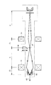
このX線発生装置は,第1の電子レンズ14と第2の電子レンズ18の間において,電子ビーム12の経路上に結像確認用ターゲット28を選択的に配置することができる。図2は結像確認用ターゲット28が電子ビーム12の経路から外れた位置(以下,退避位置という)にある状態を示している。一方,図3は結像確認用ターゲット28が電子ビーム12の経路上の位置(以下,挿入位置という)にある状態を示している。図3に示すように,結像確認用ターゲット28が挿入位置にあると,電子ビーム12は結像確認用ターゲット28に当たり,そこからX線44が発生する。このX線44を観察することで,距離f1における結像状態を確認できる。図2と図3において,結像確認用ターゲット28は,電子ビーム12の経路に対して垂直に移動することで(すなわち矢印29の方向に移動することで),退避位置と挿入位置とが切り換えられるようになっている。なお,この矢印29は,単に位置の切り換えが可能であることを原理的に示しているだけであって,結像確認用ターゲット28の実際の動きは,このような方向の動きに限定されない。
In this X-ray generator, an
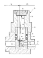
図5は結像確認装置の側面断面図である。結像確認用ターゲット28は挿入位置の状態にある。また,図6は結像確認用ターゲットの挿入位置と退避位置を示す水平断面図であり,これらの水平断面図は電子ビームの経路を含む水平面で切断したものである。
FIG. 5 is a side sectional view of the imaging confirmation apparatus. The
図5において,結像確認装置66は,結像確認ターゲット28の位置を切り換えるためのの位置切換機構と,観察窓46とを備えている。位置切換機構は,ターゲット支持体30と操作体32とケーシング34を備えている。ターゲット支持体30は外周が円筒面である。このターゲット支持体30は,ケーシング34に形成された円筒状の穴の中に回転可能に挿入されている。ケーシング34の内部は真空であり,ターゲット支持体30とケーシング34の間はOリング36で真空シールされている。ターゲット支持体30には,図6(A)に示すように,水平の貫通孔38が形成されている。この貫通孔38は断面が矩形である。この貫通孔38に対して垂直になるように孔40が形成されている。孔40を通過した電子ビーム12は結像確認用ターゲット28に当たるようになっている。
In FIG. 5, the
図5に戻って,ターゲット支持体30の貫通孔38の側壁に,銅製の結像確認用ターゲット28が固定されている。この結像確認用ターゲット28の表面は鉛直面からわずかに傾斜している。結像確認用ターゲット28の上方にはベリリウム窓42が配置されている。ベリリウム窓42の上方は,X線44が通過するための空間になっている。この空間は,ターゲット支持体30内に形成された円筒状の孔50で作られている。ベリリウム窓42の直上にはメッシュ48(図7も参照)が配置されている。このメッシュ48は,後述するように,結像確認に必要なものである。結像確認用ターゲット28に電子ビーム12が当たると,そこからX線44が発生し,このX線44はベリリウム窓42とメッシュ48を通過して,観察窓46の方向に向かう。
Returning to FIG. 5, an
図6(A)は結像確認用ターゲット28が挿入位置にある状態を示している。電子ビーム12は孔40を通過して結像確認用ターゲット28に当たり,そこからX線が発生する。図6(A)の状態から,ターゲット支持体30を時計方向に90度回転させると,図6(B)の状態になる。この図6(B)は結像確認用ターゲット28が退避位置にある状態を示している。電子ビーム12は貫通孔38を通過して主ターゲット20に向かう。
FIG. 6A shows a state in which the
図5に戻って,ターゲット支持体30の上端には操作体32が固定されている。操作体32は概略円筒状であり,その外周には大径部52があって,この大径部52の外周面にはローレット加工がなされている(図7を参照)。このローレット加工面のところを両側から指で挟んで,操作体32を回転させることができる。操作体32を回転させると,これに固定されたターゲット支持体30も回転する。操作体52の内部には上下方向の貫通孔53が形成されていて,その上端付近に観察窓46が固定されている。観察窓46の材質はX線防護用の鉛ガラスであり,X線44がほとんど透過しないようになっている。観察窓46の下面には蛍光塗料54が塗布されている。蛍光塗料54にX線44が当たると蛍光が発生し,この蛍光を観察窓46を通して観察者が見ることができる。
Returning to FIG. 5, the operating
図7はターゲット支持体30と操作体32の斜視図であり,中心線を含む円直面で切断した状態を示している。この図7は,結像確認用ターゲット28が挿入位置にある状態を示している。ベリリウム窓42の上にはメッシュ48が配置されている。電子ビーム12が結像確認用ターゲット28に当たると,そこからX線44が発生し,このX線44がベリリウム窓42とメッシュ48を通過して,観察窓46の下面の蛍光塗料54に当たる。
FIG. 7 is a perspective view of the
図8は結像確認用ターゲットの焦点56(電子ビームが照射されている領域)の状態を確認する方法を示す原理図である。焦点56と蛍光塗料54の間にはタングステンワイヤ58が配置されている。このワイヤ58はメッシュを構成している1本のワイヤに相当する。寸法dの焦点56から出たX線は,蛍光塗料54に当たって蛍光を発生させるが,ワイヤ58に遮られた部分は影となるので,ワイヤ58の拡大像が影となって観測される。この拡大像は,中央の全影部60と,その両側の半影部62からなる。全影部60は,焦点56内のどこからやってくるX線もワイヤ58に遮られて影となる部分である。半影部62では,焦点56内の一部からのX線はワイヤ58に遮られて影になるが,焦点56内の別の部分からのX線はワイヤ58に遮られない。したがって,半影部62は全影部60よりも影が薄くなる。
FIG. 8 is a principle diagram showing a method for confirming the state of the focal point 56 (region irradiated with the electron beam) of the imaging confirmation target. A
第1の電子レンズの励磁電流を調整して(すなわち磁界強度を調整して),焦点56の寸法dが最も小さくなるようにすれば,それが,結像確認用ターゲット上で電子ビームが正しく結像している状態となる。したがって,結像確認ターゲット上で電子ビームを結像させるには,第1の電子レンズの励磁電流を変化させて,観察窓の蛍光塗料に映るメッシュの影を観察し,そのメッシュの影が最もシャープに見えるところ,すなわち,半影部62が最も小さくなるところ,を探せばよい。
If the excitation current of the first electron lens is adjusted (that is, the magnetic field intensity is adjusted) so that the dimension d of the
焦点寸法dを知りたいときは,影の全体の寸法L3を測ることで,上述の特許文献2に記載の数式を用いて,焦点寸法dを算出することができる。すなわち,焦点56からワイヤ58までの距離L1,ワイヤ58から蛍光塗料54までの距離L2,ワイヤ58の直径D,影の寸法L3を用いて,所定の数式により焦点寸法dを算出することができる。あるいは,より正確に焦点寸法を測定するには,ミクロフォトメータを用いてX線フィルム上にワイヤ像を記録し,その記録した像から焦点寸法を算出することもできる。
When it is desired to know the focal dimension d, the focal dimension d can be calculated using the mathematical formula described in
次に,結像確認装置を電子ビームに沿った方向に移動させる方法を説明する。図10は結像確認装置の移動構造を示す側面断面図である。結像確認装置66は電子ビームに沿った方向,すなわち矢印64の方向,に移動させることができる。この移動により,結像距離f1と距離bを任意に変えることができる。
Next, a method for moving the imaging confirmation apparatus in the direction along the electron beam will be described. FIG. 10 is a side cross-sectional view showing the moving structure of the imaging confirmation apparatus. The
結像確認装置66のケーシング34の両側には,細長く延びる内筒68,70が一体に形成されている。主ターゲット側(図面の左側)の内筒68は外筒72の内部に挿入されている。そして,内筒68の先端付近の外周にはOリング74が設けられている。このOリング74により内筒68と外筒72の間を真空シールしている。一方,電子銃側(図面の右側)の内筒70は外筒76の内部に挿入されている。この内筒70の先端付近の外周にもOリングが設けられていて,外筒76との間を真空シールしている。結像確認装置66を手動で矢印64の方向に動かせば,真空シール状態を保ちながら,結像確認装置66を電子ビームに沿った方向に動かすことができる。この実施例では,f1は44〜120mmの範囲内で変えることができ,それに伴って,bは156〜80mmの範囲内で変化する。したがって,結像倍率(F/S)は,2.8〜15.0%の範囲内で変化する。
Elongated
図10は結像確認装置66が最も電子銃側に寄った位置にある状態(f1が最小)を示しており,図11は結像確認装置66が最も主ターゲット側に寄った位置にある状態(f1が最大小)を示している。
FIG. 10 shows a state where the
図10の例はOリング方式の移動装置であるが,真空を保持したままで移動できるような他の方式,例えばベローズ方式,を採用することもできる。 Although the example of FIG. 10 is an O-ring type moving device, other methods that can move while maintaining a vacuum, such as a bellows method, can also be employed.
次に,図2に示すX線発生装置の焦点サイズの調整方法を説明する。最初に,第1の電子レンズ14だけを使って主ターゲット20上に電子ビーム12を結像する実験をした。管電圧を50kVにして,第1の電子レンズ14の励磁電流を440μAにすると,電子ビーム12は主ターゲット20上に結像し,このときの焦点サイズは約64μmであった。
Next, a method for adjusting the focus size of the X-ray generator shown in FIG. 2 will be described. First, an experiment was performed in which the
次に,2段式の電子レンズを用いて実験をした。焦点サイズFを所望の値にするには,まず,その焦点サイズFが得られるような位置に,結像確認装置を矢印64の方向に移動させる。例えば,2μmの焦点サイズFを得たい場合には,図9の(1)式においてF=2μmを代入すると,f1=50mm,b=150mmが得られる。そのような値になるように,結像確認装置を矢印64の方向に移動させる。次に,図5の操作体32を回転させて,ターゲット支持体30を回転させ,結像確認用ターゲット28を図6(A)の挿入位置の状態にする。それから,管電圧を50kVに設定して,第1の電子レンズ14の励磁電流を変化させて,図5の観察窓46でX線44によるメッシュ48の影を観察する。そして,メッシュ48の影が最もシャープになるように励磁電流を調整する。これによって,第1の結像点16の位置が,ちょうど結像確認用ターゲット28の位置と一致する。実験によれば,このときの第1の電子レンズ14の励磁電流I1は618μAであった。
Next, an experiment was conducted using a two-stage electron lens. In order to set the focus size F to a desired value, first, the imaging confirmation apparatus is moved in the direction of the
次に,結像確認用ターゲット28を図6(B)の退避位置に戻して,図2に示すように電子ビーム12を主ターゲット20に当てる。そして,主ターゲット20から発生するX線23について,そのワイヤ像を図8に示す方法で観測して,,ワイヤ像が最もシャープになるように,第2の電子レンズ18の励磁電流を調整する。その結果,主ターゲット20上の焦点サイズは2μmになった。このときの第2の電子レンズの励磁電流I2は393μAであった。
Next, the
同様にして,各種の焦点サイズFを作ったときの,結像距離f1,距離b,第1の電子レンズの励磁電流I1,第2の電子レンズの励磁電流I2の値を,図9の表1に示す。このように,本発明のX線発生装置によれば,2μmという非常に小さな焦点サイズにして,高い分解能を確保することもできるし,また,焦点サイズを16μmと比較的大きくして,分解能は劣るが強度の高いX線を発生させることもできる。 Similarly, the values of the imaging distance f1, the distance b, the excitation current I1 of the first electronic lens, and the excitation current I2 of the second electron lens when various focus sizes F are made are shown in the table of FIG. It is shown in 1. As described above, according to the X-ray generator of the present invention, it is possible to secure a high resolution with a very small focal size of 2 μm, and a relatively large focal size of 16 μm. Inferior but high intensity X-rays can also be generated.
主ターゲット上の焦点サイズが5μmのときは,主ターゲットに投入可能な負荷は,推定で2ワットである。10μmのときは4.2ワット,20μmのときは8.5ワットである。 When the focal spot size on the main target is 5 μm, the load that can be applied to the main target is estimated to be 2 watts. It is 4.2 watts at 10 μm and 8.5 watts at 20 μm.
ところで,X線発生装置の製造時の検査のときには,ミクロフォトメータを用いて,主ターゲットの焦点サイズを正確に測定することができる。その後は,所望の焦点サイズを得たい場合には,結像確認装置を動かすだけでよく,焦点サイズは,結像確認装置の位置に基づいて,図9の(1)式で計算できる。したがって,焦点サイズを変更するときは,ミクロフォトメータのような記録装置は使わずに,主ターゲットからの主X線を用いてワイヤまたはメッシュの像を観測しながら,その像が最もシャープになるように第2の電子レンズのレンズ電流を調整すればよい。 By the way, at the time of inspection at the time of manufacture of the X-ray generator, the focus size of the main target can be accurately measured using a microphotometer. Thereafter, in order to obtain a desired focus size, it is only necessary to move the imaging confirmation device, and the focus size can be calculated by equation (1) in FIG. 9 based on the position of the imaging confirmation device. Therefore, when changing the focal spot size, the image becomes sharpest while observing the wire or mesh image using the main X-rays from the main target without using a recording device such as a microphotometer. Thus, the lens current of the second electron lens may be adjusted.
次に,別の実施例を説明する。図4は第2実施例についての図2と同様の側面断面図である。この実施例が図2の第1実施例と異なるところは,主ターゲットが透過型ターゲット66であることである。主X線68はターゲット66を透過してから外部に取り出される。
Next, another embodiment will be described. FIG. 4 is a side sectional view similar to FIG. 2 for the second embodiment. This embodiment is different from the first embodiment of FIG. 2 in that the main target is a
10 電子銃
12 電子ビーム
14 第1の電子レンズ
16 第1の結像点
18 第2の電子レンズ
20 主ターゲット
23 主X線
28 結像確認用ターゲット
30 ターゲット支持体
32 操作体
42 ベリリウム窓
44 結像確認用のX線
46 観察窓
48 メッシュ
54 蛍光塗料
66 結像確認装置
DESCRIPTION OF
Claims (3)
(ア)電子ビームを発生する電子ビーム発生源。
(イ)前記電子ビームを第1の結像点に結像させるための第1の電子レンズ。
(ウ)前記第1の結像点を通過した電子ビームを第2の結像点に結像させるための第2の電子レンズ。
(エ)前記第1の結像点の位置に選択的に配置可能で,電子ビームの照射を受けて結像確認用のX線を発生する結像確認用ターゲット。
(オ)前記結像確認用ターゲットから発生したX線を観察するための観察装置。
(カ)前記第2の結像点の位置に配置されて,電子ビームの照射を受けて主X線を発生する主ターゲット。 An X-ray generator having the following configuration.
(A) An electron beam source that generates an electron beam.
(A) a first electron lens for imaging the electron beam at a first imaging point;
(C) a second electron lens for forming an image of the electron beam that has passed through the first imaging point on the second imaging point;
(D) An imaging confirmation target that can be selectively placed at the position of the first imaging point and generates X-rays for imaging confirmation upon irradiation with an electron beam.
(E) An observation device for observing X-rays generated from the imaging confirmation target.
(F) A main target that is arranged at the position of the second imaging point and generates main X-rays upon irradiation with an electron beam.
Priority Applications (1)
| Application Number | Priority Date | Filing Date | Title |
|---|---|---|---|
| JP2004103311A JP2005293884A (en) | 2004-03-31 | 2004-03-31 | X-ray generator |
Applications Claiming Priority (1)
| Application Number | Priority Date | Filing Date | Title |
|---|---|---|---|
| JP2004103311A JP2005293884A (en) | 2004-03-31 | 2004-03-31 | X-ray generator |
Publications (1)
| Publication Number | Publication Date |
|---|---|
| JP2005293884A true JP2005293884A (en) | 2005-10-20 |
Family
ID=35326608
Family Applications (1)
| Application Number | Title | Priority Date | Filing Date |
|---|---|---|---|
| JP2004103311A Pending JP2005293884A (en) | 2004-03-31 | 2004-03-31 | X-ray generator |
Country Status (1)
| Country | Link |
|---|---|
| JP (1) | JP2005293884A (en) |
Cited By (4)
| Publication number | Priority date | Publication date | Assignee | Title |
|---|---|---|---|---|
| JP2009193789A (en) * | 2008-02-13 | 2009-08-27 | Hamamatsu Photonics Kk | X-ray generator |
| CN109637692A (en) * | 2019-01-23 | 2019-04-16 | 深圳铭杰医疗科技有限公司 | Track rectifier suitable for charged particle beam |
| CN115394619A (en) * | 2022-08-08 | 2022-11-25 | 无锡日联科技股份有限公司 | Method for enabling open type X-ray tube to have multiple working modes |
| CN115841935A (en) * | 2023-02-20 | 2023-03-24 | 安徽科昂新材料科技有限公司 | An X-ray source device |
-
2004
- 2004-03-31 JP JP2004103311A patent/JP2005293884A/en active Pending
Cited By (5)
| Publication number | Priority date | Publication date | Assignee | Title |
|---|---|---|---|---|
| JP2009193789A (en) * | 2008-02-13 | 2009-08-27 | Hamamatsu Photonics Kk | X-ray generator |
| CN109637692A (en) * | 2019-01-23 | 2019-04-16 | 深圳铭杰医疗科技有限公司 | Track rectifier suitable for charged particle beam |
| CN109637692B (en) * | 2019-01-23 | 2023-12-19 | 深圳铭杰医疗科技有限公司 | Trajectory corrector suitable for charged particle beam |
| CN115394619A (en) * | 2022-08-08 | 2022-11-25 | 无锡日联科技股份有限公司 | Method for enabling open type X-ray tube to have multiple working modes |
| CN115841935A (en) * | 2023-02-20 | 2023-03-24 | 安徽科昂新材料科技有限公司 | An X-ray source device |
Similar Documents
| Publication | Publication Date | Title |
|---|---|---|
| EP3093867B1 (en) | X-ray generator and adjustment method therefor | |
| US7218703B2 (en) | X-ray microscopic inspection apparatus | |
| JP5395118B2 (en) | Objective lens for electron microscope system and electron microscope system | |
| Loretto | Electron beam analysis of materials | |
| US7221731B2 (en) | X-ray microscopic inspection apparatus | |
| KR100499427B1 (en) | Objective lens for a charged particle beam device | |
| US7825378B2 (en) | Method for obtaining a scanning transmission image of a sample in a particle-optical apparatus | |
| JPH07296751A (en) | X-ray tube device | |
| WO2004064106A1 (en) | X-ray equipment | |
| JPWO2018025849A1 (en) | Charged particle beam apparatus and scanning electron microscope | |
| US10103002B1 (en) | Method for generating an image of an object and particle beam device for carrying out the method | |
| JP2001319608A (en) | Micro focus X-ray generator | |
| JP6967340B2 (en) | Combined beam device | |
| JP4954526B2 (en) | X-ray tube | |
| JP4828433B2 (en) | Focusing lens for charged particle beam | |
| JP4029209B2 (en) | High resolution X-ray microscope | |
| JP5458472B2 (en) | X-ray tube | |
| JP2005293884A (en) | X-ray generator | |
| JP4886760B2 (en) | X-ray equipment | |
| JP2007212468A (en) | High resolution X-ray microscopic inspection system | |
| JP4914178B2 (en) | Schottky electron gun and charged particle beam apparatus equipped with Schottky electron gun | |
| JP2012142129A (en) | Soft x-ray source | |
| WO2019049261A1 (en) | Electron gun and electron beam application device | |
| KR20190040265A (en) | X-ray tube | |
| JP5210088B2 (en) | Electron beam equipment |