JP2005293876A - Fuel cell stack - Google Patents
Fuel cell stack Download PDFInfo
- Publication number
- JP2005293876A JP2005293876A JP2004102991A JP2004102991A JP2005293876A JP 2005293876 A JP2005293876 A JP 2005293876A JP 2004102991 A JP2004102991 A JP 2004102991A JP 2004102991 A JP2004102991 A JP 2004102991A JP 2005293876 A JP2005293876 A JP 2005293876A
- Authority
- JP
- Japan
- Prior art keywords
- cell stack
- corrosion resistance
- fuel cell
- metal separator
- surface treatment
- Prior art date
- Legal status (The legal status is an assumption and is not a legal conclusion. Google has not performed a legal analysis and makes no representation as to the accuracy of the status listed.)
- Granted
Links
Images

Classifications
-
- Y—GENERAL TAGGING OF NEW TECHNOLOGICAL DEVELOPMENTS; GENERAL TAGGING OF CROSS-SECTIONAL TECHNOLOGIES SPANNING OVER SEVERAL SECTIONS OF THE IPC; TECHNICAL SUBJECTS COVERED BY FORMER USPC CROSS-REFERENCE ART COLLECTIONS [XRACs] AND DIGESTS
- Y02—TECHNOLOGIES OR APPLICATIONS FOR MITIGATION OR ADAPTATION AGAINST CLIMATE CHANGE
- Y02E—REDUCTION OF GREENHOUSE GAS [GHG] EMISSIONS, RELATED TO ENERGY GENERATION, TRANSMISSION OR DISTRIBUTION
- Y02E60/00—Enabling technologies; Technologies with a potential or indirect contribution to GHG emissions mitigation
- Y02E60/30—Hydrogen technology
- Y02E60/50—Fuel cells
Landscapes
- Fuel Cell (AREA)
Abstract
【課題】 メタルセパレータの耐腐食性の向上と低コスト化を両立できる燃料電池スタックを提案する。
【解決手段】 本発明の燃料電池スタック(10)は、電解質膜の両面をアノード極とカソード極で挟持し更にその外側を一対のメタルセパレータで挟持して成る単セル(20)を所定数積層したセルスタック(21)を備えており、セルスタック(21)のマイナス側に位置するメタルセパレータよりもプラス側に位置するメタルセパレータに対して相対的に耐腐食性の高い表面処理を施している。全てのメタルセパレータに同程度の耐腐食性の表面処理をする場合に比べて遜色のない耐腐食性を維持しつつ、低コスト化を実現できる。
【選択図】 図1
PROBLEM TO BE SOLVED: To propose a fuel cell stack capable of improving both corrosion resistance and cost reduction of a metal separator.
A fuel cell stack (10) according to the present invention comprises a predetermined number of unit cells (20) in which both sides of an electrolyte membrane are sandwiched between an anode and a cathode and the outside is sandwiched between a pair of metal separators. The cell stack (21) is provided, and the metal separator located on the plus side of the cell separator (21) is subjected to a surface treatment having relatively higher corrosion resistance than the metal separator located on the minus side. . Compared to the case where all metal separators are subjected to the same level of corrosion resistance as the surface treatment, it is possible to realize cost reduction while maintaining the same corrosion resistance.
[Selection] Figure 1
Description
本発明は燃料電池スタックに関し、特に、メタルセパレータの耐腐食性の向上と低コスト化の両立を図る改良技術に関する。 The present invention relates to a fuel cell stack, and more particularly to an improved technique for achieving both improvement in corrosion resistance and cost reduction of a metal separator.
固体高分子型燃料電池スタックは固体高分子電解質膜の両面にそれぞれアノード極とカソード極を対向配置し、更にその外側を一対のセパレータで挟持してなる単セルを所定数積層したスタック構造を成している。ステンレス等のメタルセパレータを用いる場合、メタルセパレータが高温で酸化性の雰囲気に曝されるため、長時間使用すると金属の腐食や溶解が生じる。メタルセパレータが腐食すると、溶出した金属イオンが固体高分子電解質膜に拡散し、イオン交換サイトにトラップされて固体高分子電解質膜自体のイオン導電性が低下する。また、メタルセパレータの穴あきによる反応ガスの漏出や、シールラインを侵食することによる冷却水の漏出などが生じる。このような不都合を回避するため、特開2000−21418号公報には、導電性セパレータの表面を酸性雰囲気に不活性な金属層、例えば、金又は銀で表面処理(メッキ処理)する技術が提案されている。
しかし、燃料電池スタックを構成する全てのメタルセパレータについて、金又は銀などの貴金属で表面処理を行うと、製造コストが高くなる。 However, if all the metal separators constituting the fuel cell stack are subjected to surface treatment with a noble metal such as gold or silver, the manufacturing cost increases.
そこで、本発明はメタルセパレータの耐腐食性の向上と低コスト化を両立できる燃料電池スタックを提案することを課題とする。 Therefore, an object of the present invention is to propose a fuel cell stack capable of achieving both improvement in corrosion resistance and cost reduction of a metal separator.
上記の課題を解決するため、本発明の燃料電池スタックは電解質膜の両面をアノード極とカソード極で挟持し更にその外側を一対のメタルセパレータで挟持して成る単セルを所定数積層したセルスタックを備える燃料電池スタックであって、セルスタックのマイナス側に位置するメタルセパレータよりもプラス側に位置するメタルセパレータに対して相対的に耐腐食性の高い表面処理を施している。全てのメタルセパレータに同程度の耐腐食性の表面処理をする場合に比べて遜色のない耐腐食性を維持しつつ、低コスト化を実現できる。耐腐食性の表面処理を施す箇所としては、例えば、セルスタックを冷却するための冷却水、又はセルスタックに供給される反応ガスに含まれる水分がメタルセパレータに触れる部位を選定するのが望ましい。 In order to solve the above-mentioned problems, a fuel cell stack according to the present invention is a cell stack in which a predetermined number of single cells each having both surfaces of an electrolyte membrane sandwiched between an anode and a cathode and sandwiched between a pair of metal separators are stacked. The metal separator located on the positive side of the cell stack is subjected to a surface treatment with relatively higher corrosion resistance than the metal separator located on the negative side of the cell stack. Compared to the case where all metal separators are subjected to the same level of corrosion resistance as the surface treatment, it is possible to realize cost reduction while maintaining the same corrosion resistance. As a location where the corrosion-resistant surface treatment is performed, it is desirable to select, for example, a portion where the water contained in the reaction gas supplied to the cell stack or cooling water for cooling the cell stack contacts the metal separator.
本発明によれば全てのメタルセパレータに同程度の耐腐食性の表面処理をする場合に比べて遜色のない耐腐食性を維持しつつ、低コスト化を実現できる。 According to the present invention, it is possible to realize cost reduction while maintaining corrosion resistance comparable to the case where all metal separators are subjected to the same level of corrosion resistance as surface treatment.
本実施形態の燃料電池スタックは、セルスタックのマイナス側に位置するメタルセパレータよりもプラス側に位置するメタルセパレータに対して相対的に耐腐食性の高い表面処理を施している。セルスタックのプラス側端部に介挿された数枚のメタルセパレータの冷却水通路には酸化電流が流れ、しかも、プラス側端部で局所的に酸化電流が急増する。メタルセパレータの電気的な腐食はセルスタックのプラス側端部でのみ発生し易いため、メタルセパレータの腐食対策は、主として、プラス側端部に重点をおく必要がある。セルスタックのマイナス側に位置するメタルセパレータよりもプラス側に位置するメタルセパレータに対して相対的に耐腐食性の高い表面処理を施すことで、全てのメタルセパレータに同程度の耐腐食性の表面処理をする場合に比べて遜色のない耐腐食性を維持しつつ、低コスト化を実現できる。 In the fuel cell stack according to the present embodiment, a surface treatment having relatively higher corrosion resistance is applied to the metal separator located on the plus side than the metal separator located on the minus side of the cell stack. An oxidation current flows through the cooling water passages of several metal separators inserted in the plus side end of the cell stack, and the oxidation current rapidly increases locally at the plus side end. Since the electrical corrosion of the metal separator is likely to occur only at the positive side end of the cell stack, it is necessary to mainly focus on the positive side end of the metal separator. By applying a surface treatment with higher corrosion resistance to the metal separator located on the plus side than the metal separator located on the minus side of the cell stack, all metal separators have the same level of corrosion resistance. Cost reduction can be realized while maintaining corrosion resistance comparable to that in the case of processing.
図1は本実施例の燃料電池スタック10の説明図である。同図(a)に示すように、燃料電池スタック10は電解質膜の両面をアノード極とカソード極で挟持し更にその外側を一対のメタルセパレータで挟持して成る単セル20を直列に所定数積層したセルスタック21を備えている。セルスタック21の両端部には電力取り出し用の一対のターミナルプレート31,32が配置されている。ターミナルプレート31,32の外側は絶縁プレート41,42を介して一対のエンドプレート51,52によって挟装されている。セルスタック21の内部に貫設された冷却水路(図示せず)にはプラス側端部において局所的に酸化電流が流れる(同図(b))。酸化電流はセルスタック21のプラス側端部で急増する。セルスタック21のうち所定の閾値以上の酸化電流が流れる部位PAには耐腐食性の表面処理が施されたメタルセパレータが介挿され、閾値未満の酸化電流が流れる部位PBには耐腐食性の表面処理が施されていないメタルセパレータが介挿されている。閾値としては、メタルセパレータの耐腐食性向上と低コスト化の両立を図る観点から適度な電流値に設定するのが望ましいが、酸化電流はセルスタック21の一部でのみ局所的に流れるため、少しでも酸化電流が流れる部位に耐腐食性表面処理済みのメタルセパレータを介挿してもよい。
FIG. 1 is an explanatory diagram of a fuel cell stack 10 of this embodiment. As shown in FIG. 1 (a), the fuel cell stack 10 has a predetermined number of
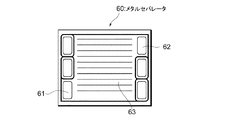
図2はメタルセパレータ60の平面図である。耐腐食性の表面処理を施す部位としては水分が触れる箇所が望ましい。例えば、冷却水入口マニホールド61、冷却水出口マニホールド62、及び冷却面63などの部位に耐腐食性の表面処理を施すのがよい。メタルセパレータ60に触れる水分は、単セル20を冷却するための冷却水だけでなく、単セル20に供給される反応ガス(燃料ガス、酸化ガス)が電池反応をすることによって生じた生成水や、結露等で生じた結露水なども含まれるため、反応ガスの入口マニホールド、出口マニホールド、及びガスチャンネルなどにも耐腐食性の表面処理を施すのが望ましい。また、メタルセパレータ60のうち水分が触れる箇所には耐腐食性の高い表面処理を施し、水分が触れない箇所には耐腐食性の低い表面処理を施すようにしてもよい。耐腐食性の高い表面処理としては、例えば、金又は銀などの貴金属を用いたメッキ処理や、厚膜のメッキ処理などがある。耐腐食性の低い表面処理としては、例えば、薄膜のメッキ処理などがある。
FIG. 2 is a plan view of the metal separator 60. As a part to be subjected to the corrosion-resistant surface treatment, a part that is in contact with moisture is desirable. For example, a corrosion-resistant surface treatment may be applied to parts such as the cooling
本実施例によれば、閾値以上の酸化電流が流れる部位PAのみに耐腐食性表面処理が施されたメタルセパレータ60を介挿しているため、セルスタック21を構成する全てのメタルセパレータ60に耐腐食性の表面処理をする場合に比べて遜色のない耐腐食性を維持しつつ、低コスト化を実現できる。
According to the present embodiment, since the metal separator 60 subjected to the corrosion-resistant surface treatment is inserted only in the portion PA where the oxidation current exceeding the threshold flows, all the metal separators 60 constituting the
本実施例では閾値以上の酸化電流が流れる部位PAに耐腐食性の高い表面処理を施したメタルセパレータ60を介挿し、閾値未満の酸化電流が流れる部位PBに耐腐食性の低い表面処理を施したメタルセパレータ60を介挿している。同一の部位PA(又は部位PB)内に介挿されるメタルセパレータ60に施される表面処理の耐腐食性の程度は同程度でもよいが、セルスタック21のマイナス側からプラス側にかけて次第に耐腐食性の程度が高くなるようにしてもよい。
In this embodiment, a metal separator 60 having a surface treatment with high corrosion resistance is inserted in a portion PA where an oxidation current exceeding the threshold flows, and a surface treatment with low corrosion resistance is applied to a portion PB where the oxidation current less than the threshold flows. A metal separator 60 is inserted. Although the degree of corrosion resistance of the surface treatment applied to the metal separator 60 inserted in the same part PA (or part PB) may be the same, the corrosion resistance gradually increases from the minus side to the plus side of the
本実施例によれば、メタルセパレータ60に施される表面処理の耐腐食性の程度をセルスタック21の位置(又は酸化電流の大きさ)に応じて変えているため、セルスタック21を構成する全てのメタルセパレータ60に耐腐食性の表面処理をする場合に比べて遜色のない耐腐食性を維持しつつ、低コスト化を実現できる。
According to the present embodiment, since the degree of corrosion resistance of the surface treatment applied to the metal separator 60 is changed according to the position of the cell stack 21 (or the magnitude of the oxidation current), the
10…燃料電池スタック 20…セル 21…セルスタック 31,32…ターミナルプレート 41,42…絶縁プレート 51,52…エンドプレート 60…メタルセパレータ 61…冷却水入口マニホールド 62…冷却水出口マニホールド 63…冷却面
DESCRIPTION OF SYMBOLS 10 ...
Claims (2)
2. The fuel cell stack according to claim 1, wherein the corrosion-resistant surface treatment is a portion where moisture contained in cooling water for cooling the cell stack or a reaction gas supplied to the cell stack touches the metal separator. The fuel cell stack applied to
Priority Applications (5)
| Application Number | Priority Date | Filing Date | Title |
|---|---|---|---|
| JP2004102991A JP4614121B2 (en) | 2004-03-31 | 2004-03-31 | Fuel cell stack |
| PCT/JP2005/005611 WO2005099019A1 (en) | 2004-03-31 | 2005-03-18 | Fuel cell stack |
| CA002528689A CA2528689C (en) | 2004-03-31 | 2005-03-18 | Fuel cell stack |
| DE112005000023T DE112005000023B4 (en) | 2004-03-31 | 2005-03-18 | fuel cell stack |
| US11/311,276 US7855026B2 (en) | 2004-03-31 | 2005-12-20 | Fuel cell stack |
Applications Claiming Priority (1)
| Application Number | Priority Date | Filing Date | Title |
|---|---|---|---|
| JP2004102991A JP4614121B2 (en) | 2004-03-31 | 2004-03-31 | Fuel cell stack |
Publications (2)
| Publication Number | Publication Date |
|---|---|
| JP2005293876A true JP2005293876A (en) | 2005-10-20 |
| JP4614121B2 JP4614121B2 (en) | 2011-01-19 |
Family
ID=35326600
Family Applications (1)
| Application Number | Title | Priority Date | Filing Date |
|---|---|---|---|
| JP2004102991A Expired - Fee Related JP4614121B2 (en) | 2004-03-31 | 2004-03-31 | Fuel cell stack |
Country Status (1)
| Country | Link |
|---|---|
| JP (1) | JP4614121B2 (en) |
Cited By (3)
| Publication number | Priority date | Publication date | Assignee | Title |
|---|---|---|---|---|
| JP2018181571A (en) * | 2017-04-11 | 2018-11-15 | トヨタ自動車株式会社 | Fuel cell stack |
| DE102018111481A1 (en) | 2017-06-15 | 2018-12-20 | Toyota Jidosha Kabushiki Kaisha | fuel cell stack |
| JP2020057488A (en) * | 2018-10-01 | 2020-04-09 | 本田技研工業株式会社 | Fuel cell stack |
Citations (3)
| Publication number | Priority date | Publication date | Assignee | Title |
|---|---|---|---|---|
| JPS62295356A (en) * | 1986-06-13 | 1987-12-22 | Hitachi Ltd | Fuel cell |
| JPH05325993A (en) * | 1992-05-20 | 1993-12-10 | Sanyo Electric Co Ltd | Fuel cell |
| JP2001216978A (en) * | 2000-02-07 | 2001-08-10 | Toyota Motor Corp | Method for removing insulating film from fuel cell and metal separator |
-
2004
- 2004-03-31 JP JP2004102991A patent/JP4614121B2/en not_active Expired - Fee Related
Patent Citations (3)
| Publication number | Priority date | Publication date | Assignee | Title |
|---|---|---|---|---|
| JPS62295356A (en) * | 1986-06-13 | 1987-12-22 | Hitachi Ltd | Fuel cell |
| JPH05325993A (en) * | 1992-05-20 | 1993-12-10 | Sanyo Electric Co Ltd | Fuel cell |
| JP2001216978A (en) * | 2000-02-07 | 2001-08-10 | Toyota Motor Corp | Method for removing insulating film from fuel cell and metal separator |
Cited By (9)
| Publication number | Priority date | Publication date | Assignee | Title |
|---|---|---|---|---|
| JP2018181571A (en) * | 2017-04-11 | 2018-11-15 | トヨタ自動車株式会社 | Fuel cell stack |
| DE102018111481A1 (en) | 2017-06-15 | 2018-12-20 | Toyota Jidosha Kabushiki Kaisha | fuel cell stack |
| KR20180136893A (en) | 2017-06-15 | 2018-12-26 | 도요타지도샤가부시키가이샤 | Fuel cell stack |
| JP2019003840A (en) * | 2017-06-15 | 2019-01-10 | トヨタ自動車株式会社 | Fuel cell stack |
| KR102076143B1 (en) * | 2017-06-15 | 2020-02-11 | 도요타지도샤가부시키가이샤 | Fuel cell stack |
| US10559833B2 (en) | 2017-06-15 | 2020-02-11 | Toyota Jidosha Kabushiki Kaisha | Fuel cell stack |
| DE102018111481B4 (en) | 2017-06-15 | 2026-03-19 | Toyota Jidosha Kabushiki Kaisha | Fuel cell stack |
| JP2020057488A (en) * | 2018-10-01 | 2020-04-09 | 本田技研工業株式会社 | Fuel cell stack |
| JP7076350B2 (en) | 2018-10-01 | 2022-05-27 | 本田技研工業株式会社 | Fuel cell stack |
Also Published As
| Publication number | Publication date |
|---|---|
| JP4614121B2 (en) | 2011-01-19 |
Similar Documents
| Publication | Publication Date | Title |
|---|---|---|
| US8173320B2 (en) | Fuel cell stack and method for making the same | |
| EP2025027B1 (en) | Fuel cell stack and method of producing its separator plates | |
| JP4920137B2 (en) | Operation method of polymer electrolyte fuel cell | |
| KR101941739B1 (en) | Fuel cell stack | |
| JP3936095B2 (en) | Fuel cell | |
| JP4047265B2 (en) | Fuel cell and cooling separator used therefor | |
| JP2004103296A (en) | Polymer electrolyte fuel cell | |
| US9246178B2 (en) | Method to minimize the impact of shunt currents through aqueous based coolants on PEM fuel cell bipolar plates | |
| JP4614121B2 (en) | Fuel cell stack | |
| CN100370645C (en) | fuel cell stack | |
| JP6910923B2 (en) | Fuel cell stack | |
| JP2006100021A (en) | Fuel cell stack | |
| WO2005099019A1 (en) | Fuel cell stack | |
| JP4862256B2 (en) | Flat type polymer electrolyte fuel cell separator | |
| JP4726182B2 (en) | Fuel cell stack | |
| JP6838503B2 (en) | Fuel cell stack | |
| US7575827B2 (en) | Conductive coatings for PEM fuel cell electrodes | |
| JP4862257B2 (en) | Flat type polymer electrolyte fuel cell separator | |
| JP4183428B2 (en) | Fuel cell | |
| JP4887732B2 (en) | Fuel cell system | |
| JP2006164897A (en) | Metal separator for fuel cell | |
| JP2007095388A (en) | Method for manufacturing metal separator for fuel cell, manufacturing apparatus, and metal separator for fuel cell | |
| JP2022077279A (en) | Fuel cell separator | |
| JP2003187821A (en) | Fuel cell | |
| JP2018120805A (en) | FUEL CELL SYSTEM AND METHOD OF OPERATING FUEL CELL SYSTEM |
Legal Events
| Date | Code | Title | Description |
|---|---|---|---|
| A621 | Written request for application examination |
Free format text: JAPANESE INTERMEDIATE CODE: A621 Effective date: 20061127 |
|
| A131 | Notification of reasons for refusal |
Free format text: JAPANESE INTERMEDIATE CODE: A131 Effective date: 20100519 |
|
| A521 | Request for written amendment filed |
Free format text: JAPANESE INTERMEDIATE CODE: A523 Effective date: 20100716 |
|
| TRDD | Decision of grant or rejection written | ||
| A01 | Written decision to grant a patent or to grant a registration (utility model) |
Free format text: JAPANESE INTERMEDIATE CODE: A01 Effective date: 20100924 |
|
| A01 | Written decision to grant a patent or to grant a registration (utility model) |
Free format text: JAPANESE INTERMEDIATE CODE: A01 |
|
| A61 | First payment of annual fees (during grant procedure) |
Free format text: JAPANESE INTERMEDIATE CODE: A61 Effective date: 20101007 |
|
| R151 | Written notification of patent or utility model registration |
Ref document number: 4614121 Country of ref document: JP Free format text: JAPANESE INTERMEDIATE CODE: R151 |
|
| FPAY | Renewal fee payment (event date is renewal date of database) |
Free format text: PAYMENT UNTIL: 20131029 Year of fee payment: 3 |
|
| LAPS | Cancellation because of no payment of annual fees |